Manufacturing guy-at-large.

Filtering by Tag: manufacturing

Looking for a laser marking vendor

Added on by Spencer Wright.

An open RFQ:

I am looking for a vendor who can perform laser marking services on stainless steel parts. This is a customization that we offer for The Public Radio as seen below; we purchase the laser marking in MOQs of 100+ and have an estimated total usage of 2500 this year. 

The Public Radio - Custom engraving - large.jpg

If you do laser marking or know someone who does, please get in touch here. Note, my preference is to find a supplier that's within 1 day of ground shipping from New York City. 

A month or so of TPR work

Added on by Spencer Wright.

The Public Radio is in preproduction.

First: I spent part of week in Taiwan, Shenzhen, and Dongguan in late June visiting a few of our component suppliers, and parts started trickling in at our manufacturing partner last week. Proof:

A few notes here:

  • A huge thanks to Lucas, who came with me to the speaker factory and was just generally a hospitable guy while I was in Hong Kong & Shenzhen. Thanks also to Kuji for showing me an awesome time (see this video) in Shenzhen. 
  • Visiting our speaker manufacturer for the second time (the first time was two years ago) was great. Knowing our suppliers is a real treat, and I've very much enjoyed working with them.
  • Seeing the mold for our new custom speaker was big. This was an investment - both in the tool itself and in our relationship with our speaker factory - but it makes The Public Radio more robust and *much* easier to put together. It reduces the assembly's total number of parts and allows us to use larger screws, which are easier to handle and will take less time to install. That both saves us money and makes TPR an overall nicer product. This is also the second injection molded part I've ever designed and is *slightly* more complex than the one before it, so from a personal standpoint it was *really* fun to actually touch.
  • China, as always, is just mind boggling. I especially appreciated Ofo, which is amazing.

Second: Since then, I've been dealing with our remaining procurement issues (mostly logistics & cash flow planning; some vendor management) and then hammering on our actual manufacturing plan. The Public Radio has an extremely simple user interface, and to create that there's a *ton* of work that goes into managing the assembly & fulfillment process. This involves a few special things:

  1. As Zach and I discussed with Gabe on The Prepared's podcast a few weeks ago, we've now got a fully custom order management database which coordinates customers, tuning frequencies, and shipping data (and a few other little things).
  2. An instance of Tulip, which will handle not only our assembly training but is also acting as the connective tissue between our database and the real world. Tulip will coordinate barcode scans, assembly steps, and our radio programming jig to keep everything in sync. It also logs productivity and can help track defects down the road. In short, it's awesome.
  3. Our radio programming jig. Josh is taking a crack at this (among other things :) now, and hoping to make it more reliable & robust than the ones that we used on the first batch of Public Radios two years ago. 

These three things are *just* starting to really come together this week; I've got maybe a third of it all running on my desk right now.

Next up: We should have a fully functional prototype of our manufacturing system running in two weeks. We'll be testing it in NYC for about a week, and will then bring the whole thing to Chicago to fit it into Accelerated Assemblies' processes. By then we'll have all of our materials on site and, after a short run or two to iron out any kinks, will be in full production mode.

More soon :)

Stamping die changes

Added on by Spencer Wright.

So, Zach and I have been working on an updated version of The Public Radio, and I figure we're about due for a manufacturing update. So! Here goes:

This is the same progressive stamping die I've shown here, but with some small changes. The locations and diameters of our main assembly screws have changed, and as a result the tool needed to be modified. 

The cool thing about progressive stamping is that you have multiple stations - in this case five - to work with. As seen above, the stations go right to left. Initially the screw holes were punched in station one (far right), but now they're being done in station two. Making this change just requires removing four punches and then adding four new ones + corresponding holes; the old holes are simply left unused.

We've got a few other updates coming up, including visits to a few factories and a new assembly/tuning management process. Stay tuned :)

Changing the world around us

Added on by Spencer Wright.

Every few weeks, someone asks me what I think the future of 3D printing is - whether it's going to really change the way things are made.  My response is to ask if the name "PCC" means anything to them - a question that almost always elicits a blank stare.

PCC is a manufacturer of castings and forgings, primarily for aerospace and power generation. They live mostly outside of the public eye; to most folks, casting pretty much begins and ends with old-school iron cookware, and few stop to consider how improvements in casting techniques might have changed the cost and availability of electricity and air travel over the past half century.

And yet they have had a big impact. PCC sells about $10B worth of products every year, supplying critical propulsion and airframe components to companies like Boeing and Airbus. Many of these parts allow airplanes to reduce weight and improve engine efficiency, helping along significant improvements in fuel economy per seat. And so, in 2016, Precision Castparts Corp was acquired by Berkshire Hathaway for $37.2B. It's the largest amount that Warren Buffett has ever spent on an acquisition. 

I bring this up to say: The tech press may maintain their interest in 3D printing, or they may not. It's possible that, in a few years, I'll walk into a retail shop and have made-to-fit parts printed for me on demand. It's possible that manufacturing will become distributed; that supply chains will spin up and down at a moment's notice; that computers will engineer products from start to finish.

But there are many other, less sexy ways to change the world around us. And we'd all be well off if some 3D printing method achieved one of those instead.

An ode to VHB tape

Added on by Spencer Wright.

I mentioned VHB tape in a post a few weeks ago, and last week a friend, who had read it, looked at me quizzically and asked "what's up with VHB tape?"

The thing is, VHB tape is awesome. It's an industrial strength, double-sided foam adhesive, capable of creating *really* strong bonds between basically anything that you'd want to stick together. I've used it in a few contexts, and encourage anyone who takes hardware projects seriously to keep VHB tape in mind as an alternative to welding, bolting, or gluing parts together.

I first became aware of VHB tape when building bikes, and used it (as part of 3M's "mushroom head" tape, which is the same stuff that EZPass uses to stick sensors to your windshield) to create a modular front rack system that didn't require bungee cords. Later, when I was working on robot doors, I seriously considered using VHB tape to bond mahogany cladding to the doors' aluminum frames; we eventually decided on structural adhesives, and dealt with a slew of issues resulting from differences in thermal expansion rates.

Most recently, I'm using a small amount of VHB tape to adhere the 8020 subframe to the phenolic resin top of my desk. I chose a thin tape - 1/2" wide and .020" thick - and am using it on the short ends of the desktop as a secondary fastening method (the primary connections are two M5 bolts). I'm using it here for a few reasons, which highlight VHB's advantages:

  • It's really strong. Not as strong as a structural adhesive like DP420 (with its overlap shear strength of about 4500 PSI), but for applications like the ones above, VHB's ~100 PSI dynamic tensile and 1000 PSI static shear strengths are *well* within my design objectives. 
  • It's really easy to apply. In most cases, isopropyl alcohol is all I've needed to prep the surface, and it's kind of nice to not have to manually mix up epoxy or get out a mixing gun. 
  • It stretches to accommodate differences in CTE. In this way, VHB is *much* better than rivets or nuts/bolts, and has big advantages over structural adhesives as well. According to 3M, VHB tapes can be stretched up to 50% of their thickness, making them ideal for applications where dissimilar materials need to be bonded, or where some shock absorption & vibration dampening is desired.
  • It has a predictable thickness. Glue is great, but planning for a consistent glueline can be tricky. VHB is available in a variety of thicknesses, allowing you to design the assembly just the way you want it.
  • It's relatively easy to remove. Disassembling a glue joint can be a major pain in the ass, but VHB is just acrylic foam; if you can fit a knife into the joint, you can usually cut the tape in half and pull the assembly apart. 
  • It's easy to keep in stock. Glue is great, but inevitably I end up with a hardened tube laying around, or run out of mixing nozzles right when I need them. VHB doesn't need any supporting equipment, and is shelf stable for two years - whether or not you've opened the package. 

Don't get me wrong - I keep a big selection of bolts on hand, and usually have a active tubes of cyanoacrylate, Titebond, and DP420 on hand. But my shop is much better for having VHB in stock, and my desk is much better off for having used it :)

Distributed Manufacturing

Added on by Spencer Wright.

Note: This draft was started about a year and a half ago. In the name of valuing what's shipped more than what's (theoretically) perfect, I publish it now with considerably less preciousness than originally planned. 

When I took these pictures - on the street in Dongguan, PRC, in the summer of 2015 - I was thinking about the emphasis that American startup culture has placed on distributed manufacturing over the past few years. According to the narrative, distributed manufacturing is being enabled by a combination of 3D printing, streamlined digital documentation standards, and web/mobile outsourcing marketplaces. Through these, we're ostensibly moving towards a paradigm that offers unparalleled improvements in efficiency, variety, and speed-to-market.

Parts of this narrative may well be true. I'm certain, however, that neither additive, nor the model-based enerpeise, nor any digital matchmaking service is a prerequisite for distributed manufacturing. Really, all you need is real estate and some demand for (in this case) overnight EDM and machined parts. 

I tell you, seeing this was really breathtaking.  

Teardown: Nerf N-Strike Jolt Blaster

Added on by Spencer Wright.

Last week I led a bunch of NYC hardware folks through a design for manufacturing exercise in which we tore down inexpensive consumer hardware and tried to understand how they had been engineered for manufacturability. It was fun seeing a range of things be taken apart, and I wanted to do the exercise myself here.

I chose my favorite product of the night: A Nerf N-Strike Jolt Blaster, sold on Amazon for a whopping $5.99. 

Note that I discarded the packaging before taking my camera out. It was very simple - a piece of printed cardboard, a thermoformed plastic sheet, and two pieces of clear tape.

The blaster (I guess I'll use "blaster" here instead of "gun," though it seems a bit silly) comes with two darts. I took those apart first. They're made of two parts: a piece of cut-to-length blue foam tubing and a piece of molded orange and white rubber. They're glued together, probably with cyanoacrylate aka crazy glue - everything in the blaster seemed to be glued together with CA.

Next I removed the four screws at the base of the handle. These were the only screws in the entire product, and they're installed directly into the molded plastic body so no nuts are needed.

Next I removed the two rubber parts on the plunger, which had a light coating of lubricant on it. First there was an o-ring, and then there was a molded button-shaped part which was installed underneath a rivet.

With the rubber parts off, I pried the rivet (which had a barbed shaft and was pressed into the end of the orange plunger handle) out of the assembly. 

Next I removed three orange parts off of the barrel of the blaster. These appeared to be completely cosmetic.

Next I removed the blue plastic cap off of the back of the blaster. This has little false screws (colored blue as well), and was glued into the blaster body pretty securely. Behind it was a light gauge spring and the dart drive mechanism itself.

Lastly, I pressed the trigger pivot pin out of the blaster's body. I used the cap from a small brass container I made a few years ago to hold the blaster off of the vise jaw, and a torx driver bit to push the pin through the blaster body.

Here's the entire product disassembled:

The whole blaster has 24 individual parts, plus packaging. The full BOM would have 21 parts on it, plus cyanoacrylate glue and two pieces of tape. It's possible that the screws and trigger pin come off the shelf (and conceivable that the o-ring and possibly the springs do too, though I suspect they're custom), but everything else would require a significant amount of custom tooling. I count about 25 individual assembly steps required to put the whole product together. Oh - and a few of the parts are painted, too.

All of this costs $5.99.

I think this is pretty incredible.

Photos from a visit to CCAT

Added on by Spencer Wright.

A few months back I had the pleasure of visiting the Connecticut Center for Advanced Technology, which is located on the UTC/Pratt & Whitney East Hartford campus. CCAT began as a facility focused on researching laser drilling, but has moved deeper into 3D printing, and specifically directed energy deposition, in the past few years. 

In addition to a full subtractive (manual and CNC) shop, CCAT has a few cool additive tools that I was particularly interested in. The first is an Optomec 850R LENS system. The 850R is a large format directed energy deposition machine which can be used for both new parts and repairs. It's also useful for material development, as DED machines can create parts with a small amount of powder (while powder bed fusion machines generally require a large amount of powder).

(Click on the photos for larger versions + descriptions)

The other thing I was excited to see was their Kuka HA30 robot, which has a coaxial laser cladding head attached to it. This robot can be used for either etching/engraving or cladding, meaning that it can either subtract or add material to a part. Especially when combined with the two-axis rotary table shown below, this thing can create some really complex parts.

It was really cool seeing these specialized technologies being used in real life. Thanks to CCAT for having me!

Photos from an antenna factory in Shenzhen

Added on by Spencer Wright.

This past July, Zach and I visited The Public Radio's antenna supplier in Shenzhen. I had only a vague idea of how antennas were made, and it was interesting to see the process in person. It was also fascinating to see a shop that relied so much on manual and mechanically driven machinery. 

A few observations:

  • This shop manufactures a variety of parts, with the defining feature being that they're made of tubing. For our antennas, the process works basically like this:
    • Tubing is bundled together with zipties and cut to length by wire EDM.
    • Tubing ends are swaged in/out.
    • Sections are assembled into a single telescoping unit
    • Meanwhile, end fittings are manufactured from solid stock. This happens either on the automatic turret lathes, or on single-operation manual machines (lathes/drill presses).
    • End fittings are installed on the telescoping antennas, again using swaging/forming processes.
  • The whole operation was decidedly low tech and manual - almost disturbingly so. It would seem very difficult to control quality - which I guess should be expected when you're looking at a niche, and rather inexpensive, commodity product.

A few of the photos have notes on them - click to show.

Improved laser build

Added on by Spencer Wright.

Learning new software is fun. This is me after a few hours playing with Materialise Magics 19 and SG+.

I've made a few modifications to the standard build:

  • Changed the surface selection angle to 50°. This build is set up for laser metal powder bed fusion (aka DMLS), which will print angles a bit below that, and it's very possible that 50° isn't optimal.
  • Changed the upper supports so that they're angled. In my last post you'll notice that if these are vertical, they'll rest on the bottom face of the cylinder. While that may be fine structurally, it means that I'd have that much more to clean up, and I think I'd rather have the supports go all the way down to the build plate instead. It's *possible* that this will reduce the amount of post processing necessary on the part - you'd need to run multiple builds with different configurations to be sure.

It's worth noting that this part is too far off the build plate right now - I'm still trying to get used to Magics' UI, and figured it didn't matter for now. I should probably also orient the part at a slight angle from vertical (see my recent post, here, for more details on this); again, I'll play with that a bit more later.

Oh, and I probably want to add additional reinforcements to the short ID, to make sure that it prints round. I'm looking at a few methods of doing this, most of which would require some work back in solid CAD (Inventor), or *possibly* some volumetric mesh generation software (like nTopology). 

I'm definitely still getting used to Magics' philosophical perspective on the additive process chain, too. I have some thoughts on what this is, but will play around more before I share them :)

Stay tuned.

This week: Materialise Magics 19 and SG+

Added on by Spencer Wright.

Just a little teaser:

This week, in addition to the networking I'm doing (remember: I'm a free agent now, and directing my efforts toward finding the best path for myself in metal additive manufacturing), I'll be diving deep into Materialise Magics 19, the industry standard software for metal 3D printing build processing. I'm excited to learn more about its capabilities, and will share more later this week. I'll be spending most of my time working on orientations & support structures schemes for my titanium seatpost head, seen here in Magics' simulation of an EOS M280:

Magics bills itself as "The link between your CAD file and the printed part." It's used by OEMs and service bureaus alike to prepare design files to be printed - often times on the very machines that I've been building parts on (one, two) over the past year. In most cases, Magics imports an STL file. It then can be used for three big chunks of work:

  1. Fixing. In many cases the files that you import are broken in some way (edges not connected; faces oriented in the wrong direction), and can't be printed as is. Magics has a suite of tools that analyze and solve these problems.
  2. Editing. There are a variety of reasons why you'd want to edit a design before printing it, but probably the most common is that it won't fit in the build chamber of the machine it's being printed on. Magics offers tools that cut, hollow, thicken, perforate, extrude, label, boolean, and support parts and their features.
  3. Build prep. This is the part that I'm most interested in, as it directly affect the workflow that I've beed dealing with on my titanium parts. Here, the user selects the machine that the parts will be printed on. Then the parts are oriented physically within the build chamber, and an analysis is run to confirm that there are no part collisions that will affect the build.

Lastly - and of particular interest - is the SG+ module for support generation in metals. This would fall somewhere between (and across) numbers 3 and 4 above, and involves creating solid and mesh support structures that anchor the part to the build plate and provide thermal sinks to ensure a successful build. The SG+ module is a critical part of the metal 3D printing process chain today. It's used extensively across the industry, and engineers who are skilled at support generation are highly prized.

This week I'll be exploring these features (especially build prep and SG+) extensively; stay tuned for updates.

3D printing titanium: Learning to learn from success

Added on by Spencer Wright.

Dear reader — 

This report is an update to my experiences in metal 3D printing; it describes a good chunk of what I’ve been working on over the past four months. While I’d like to say that it stands on its own, I think there’s some context — especially if you’re just beginning to explore metal 3D printing — that can be gained from reading my earlier posts (starting with my long "Bin of broken dreams post") first.

For background: I believe that functional, engineered consumer products made by additive manufacturing are an inevitability. In order to prepare myself for that inevitability, I’ve been developing a line of bicycle parts made by metal powder bed fusion, a process that’s used extensively in aerospace, medical, and tooling applications. My last post described the difficulty and constraints I’ve experienced in part geometry and build orientation. Since then I’ve turned a corner, and today I can say that I’ve successfully designed, built, and tested a functional product — which at last puts me in the position of needing to learn from success.

As I’ve documented the process — and frustrations — of developing metal 3D printed parts, I’ve been pleased and surprised at the number of people who’ve reached out to me to commiserate (n.b., if you’re reading this and want to do so yourself, please drop me a line). Without exception, they have expressed solidarity. “We share all of your frustrations,” one person said. “I have been through the same pain as you,” said another. 

One of these people was Tom De Bruyne, General Manager at Layerwise. Layerwise is a Belgian company which was started out of the Catholic University of Leuven (one of the premier centers of additive manufacturing research); it was acquired by 3D Systems in late 2014. They’re famous for being one of the few service providers who built their own laser metal powder bed fusion machines, and have a ton of experience making 3D printed parts at both prototype and production scale. We struck up a conversation, and soon agreed to work together.

While popular opinion would have you think that quantity is a non-factor with 3D printing, the realities of running a service bureau are much to the contrary. To job shops, quantity is a critical factor; if a part will be produced at large volumes, every detail of its design and manufacturing life cycle must be examined. If, on the other hand, you’re printing a tool — or a prototype of a part that will be manufactured conventionally — then most shops will focus on getting the first print right without modifying its underlying geometry.

My project falls somewhere in the middle: while my design is certainly imperfect, there are many aspects of it which are very close. Moreover, it poses challenges (most notably its opposing cylinders, oriented 90° apart, and also its thin-wall construction and bolt boss) that will exist throughout any redesign, and solving them now will only improve my ability to deal with them in future iterations. 

At the current juncture, the key questions to test are:

  • Can we reliably build my current design with minimal post processing?
  • Does my current design meet the necessary performance standards (strength, security, etc.) for bicycle seatmast toppers?

In practical terms, the first question boils down to whether we can build a part that can be installed on a bicycle. This means two things: maintaining inner diameters which are round and dimensionally accurate to within +/-.006", and having a bolt boss on the long cylinder which, when tightened, is capable of securing the part to a bicycle’s seatmast.

My last prototype was built on its side, and the long cylinder’s aft wall distorted as it was sintered. We added a series of solid ribs in order to counteract the built-in stress in that wall, but it ended up like a game of whack-a-mole: each reinforcement just moved the stress somewhere else. A new approach was needed.

Unlike most of the US job shops I’ve spoken to, Layerwise bundles together many low-volume customer orders into each build; my part was printed alongside a handful of other titanium parts in one of the 15–20 machines that Layerwise designed and built themselves. This means that Layerwise is able to process a large value of parts at once, even if they’re only building prototype quantities of each design.

This poses a significant challenge: if one part fails, it can jeopardize many customers’ orders. To mitigate this risk, Layerwise constantly monitors a slew of process signatures, and can adjust machine parameters on-the-fly if they detect problems. They’re also working on a layer-based deposition control & verification system (the details of this are secretive, but it sounds similar to the optical tomography systems that other machine manufacturers are working on today). Still, each part is evaluated carefully beforehand in order to anticipate and avoid failures. Especially for short-run prototypes, it’s usually better to over engineer the support structures (and ensure a successful build) than skimp out and need to rebuild the part later.

Layerwise is secretive about their custom-built machines, but they did tell me a few details. They each contain a single laser, and are built around roughly the same form factor (275mm x 275mm x 420mm) as most of the industrial machines on the market today. I also understand that Layerwise uses a recoater blade (unlike 3D Systems’ ProX line, which uses a roller), though I couldn’t confirm whether it’s a hard material (like the high speed steel blades that most EOS machines use) or a soft one (like the polymer wipers often used on Concept Laser machines). They’re able to print in about 15 materials, with the majority of their work being done in titanium. They monitor temperature, pressure, and oxygen content on-the-fly, and are working on additional variables — including full melt pool analysis.

Layerwise has in-house wire EDM, and has a daughter company that does 5-axis CNC machining. But most prototype parts, including mine, are finished by hand. When validating a part for production, Layerwise tests the full manufacturing lifecycle, building multiple full batches of parts and sending them out to be post processed. Once they’ve validated the process, they will in some cases hand off production to other 3D Systems divisions.

Reorienting

I worked with Martijn Vanloffelt, a project engineer at Layerwise, to prepare my part to be built. He used a few key tricks:

In order to maintain roundness in the saddle clamp cylinder (the shorter of the two cylinders, which was was going to be oriented more or less parallel to the build plate), Layerwise reinforced the inner diameter with three serrated discs. 

They also oriented the part slightly off-axis in both the X and Y axes. This brings me to a point that’s worth highlighting: In metal powder bed fusion, a part’s orientation has a number of effects. First of all, any surface with an angle of less than about 45° (depending on material) must be supported. As a result, it’s generally better to orient a part so that all overhangs are as steep as possible.

From NIST Technical Note 1801, a good primer on laser metal powder bed fusion.

But in addition, one must consider the angle between the part and the recoater blade. If the part lifts up at any point during the build, the recoater blade will strike it. The longer the area of contact is, the worse the result will be. Some machine manufacturers offer alternative recoaters to lower this risk (3D Systems ProX uses a roller; EOS offers a carbon fiber brush; Arcam uses a metal comb; and both Concept Laser and SLM offer soft polymer blades), but most use a piece of high speed steel (or, in the case of older EOS machines, a ceramic blade) to spread powder across the build platform. Regardless, it is usually better to orient parts slightly off axis in the XY plane, so that the blade doesn’t contact the part’s walls all at once. 

Orienting parts off axis can also help improve surface finish. When a cylinder’s axis is aligned in the XY plane, the top face will exhibit an undesirable stepped appearance; my earlier prototypes all had this feature. When a part is oriented off axis, the surface finish is generally more consistent.

I should note that none of these techniques is guaranteed to work in all cases. Layerwise has a lot of experience building a wide variety of geometries, and has developed a sense of how to anticipate and deal with issues as they come up. I got the impression that the techniques they used on my part are things they’ve used in the past, but each design is different — and even a tried-and-true method of dealing with one design isn’t guaranteed to work well on another.

The Layerwise team also put a lot of care into generating mesh supports. Like most of the additive metal industry, Layerwise uses Materialise Magics for their final build prep, and they’ve developed expertise in exploiting the software in creative ways. I’m not able to share a detailed description of the supports Layerwise created for my part, but I can say (and anyone in the industry could confirm) that they were needed in four areas:

  1. Underneath the part to anchor it to the build plate. 
  2. Inside the saddle clamp cylinder. 
  3. Inside the window in the center funnel area. 
  4. Inside the seatmast clamp bolt boss. 

Layerwise took great care to orient the part such that it didn’t require support structures inside the hidden voids in its center section. This is something that designers and project engineers alike need to think about as a part heads into production. Not only can powder bed fusion not make fully sealed voids (if you printed a sealed sphere, the entire center would be full of trapped, unmelted powder at the end of the process), but many geometries will require support structures in areas where they’re difficult or impossible to remove. For instance, a Klein bottle could be printed in metal — but no matter how you oriented it, there would likely always be support structures stuck inside its fat end. Because of the angles in my part, it was possible to avoid this — but a different design might not fare as well.

The Parts

The first part Martijn printed was a big step forward: The build completed successfully without collapsing. However, a new problem arose. The windows on the seatmast clamp area caused the two “leaves” of that cylinder to twist as they were built. By the time the window closed back up, they had become misaligned, and a witness was clearly visible where they joined back together. The part had a clear flaw — and it wouldn’t be acceptable for production.

In the next build, Martijn added a curved, perforated disc to each of the seat mast cylinder’s windows, keeping them aligned as they grew. The part that resulted was a full success, printing with clean, smooth surfaces and good near net dimensions.

Layerwise’s second build.

Considering how much support material needed to be added back into the seatmast clamp area just to get it to build properly, I’m struck again with how inefficient my design is. The windows in the sides of the part are meant to reduce both weight and cost, but a bunch of energy is put into supporting them — and then cleaning the temporary supports out again. Instead of windows, I could just as well have replaced the walls with a lattice structure that would both decrease mass and be self-supporting during the build process, bringing the part’s cost down.

This hammers home a point that has plagued my design process: Without knowing — and, optimally, having input into — how a part is going to be oriented and supported during its build, designers are doomed to creating inefficient designs. Designing for manufacturing requires an intimate knowledge of the manufacturing process, including direct access to detailed information about how the part will be oriented and supported. But in most designer/service provider relationships today, that information comes well after many of the important design decisions have been made — if it comes at all. As a result, it often takes a large investment (both in time and money) just to prove whether additive can possibly be used to create the part at hand — and once that’s been proven, many additional iterations are sure to be needed.

This is a key problem in today’s additive manufacturing supply chain: while parts are usually designed in a solid modeling environment (often Autodesk Inventor or Solidworks, each of which cost between $5–10,000), builds are oriented and supported in Materialise Magics — which costs an additional ~$20,000. As a result, independent designers are stuck with a disjointed process, which requires costly iterations and lots of communication with the service bureau who’s preparing the part to be built.

Regardless: At this point in the process, it didn’t make sense to redesign the seatmast clamp area to reduce supports. Martijn’s build had a very high likelihood of completing successfully, and it was time to put it to the test.

It worked.

Post processing 

After printing it, Layerwise did a bunch of post processing before sending the part to me:

  1. First, the entire build plate was stress relieved. Layerwise’s stress relief process is proprietary, but a typical process would involve putting the build plate in a furnace and bringing it to 600°C over a period of an hour, then holding it there for three hours before turning it off. In theory the furnace is either argon purged or vacuumed, but in practice it may contain small amounts of oxygen too. Layerwise says that the vast majority of the stress relief that they do is performed in a vacuum, but argon is typically used on prototype parts.
  2. Then the parts were removed from the build plate. Like most shops I’ve spoken to, Layerwise uses wire EDM — though bandsaws are also common.
  3. At this point, each customer’s part is separated and processed on its own. Supports are removed by a totally unsexy manual process, often involving wrenches, picks, and mallets.
  4. Where support structures have been removed additional cleanup is usually necessary. On prototype parts, Layerwise makes extensive use of rotary grinding bits.
  5. The inner diameters of my part were both ground to their final size. Layerwise told me that this process was 100% manual, and I was blown away at the precision and consistency of the surface finish.
  6. Then, any remaining features were micro shot peened with a nonabrasive ceramic medium.

At this point, Layerwise sent me the part. Still to be done, however, was to tap the female threads in the seatmast bolt boss.

Herein lies an important point: metal 3d printing does not, in general, produce usable mechanical features like threading. In conventional manufacturing, threading is often just another step on the same machine: mills and lathes can both easily create female threads. But with additive, threading almost always requires secondary processing. As a result, the design files that are loaded into Magics only contain plain-bore thru holes; any threading specifications must be documented (and manufactured) separately.

So, the part that I received simply had a 4.2mm hole in it; it was up to me to cut the M5 female threads. “No problem,” I thought. I’ve got a tap handle right at my desk, and am more than comfortable using it. 

At this point, I became painfully aware of what’s called alpha case. Alpha case is a very hard, brittle layer of oxygen rich titanium in a part’s surface (for an interesting study on alpha case depth, see this); it’s the result of the titanium having been processed at high temperatures in environments where oxygen is present. And as I tapped the hole in the first part that Layerwise printed me, I realized that it’s very, very difficult to cut.

In order to make my job easier, I purchased a set of custom progressive taps from Widell Industries. Progressive taps cut threads in three steps, increasing the thread depth as they go. As a result, the cutting force required is generally much lower.

Even using progressive taps, I was shocked at how difficult tapping the second part was. It was incredibly slow going, and produced a lot of heat. I used cutting fluid liberally, and 45 minutes later was done.

I should note here that titanium is a hard metal regardless of how it’s processed. Moreover, alpha case is preventable; in this case, it’s simply the result of the stress relief process being done in a furnace that contains some trace oxygen. Annealed titanium 6/4 has a typical Vickers hardness of about 349, but when a part has been stress relieved in an oxygenated environment, that number might jump to more than 412. By comparison, 4130 steel and 6061-T6 aluminum (both of which are used extensively in the bicycle industry) have Vickers hardnesses of around 207 and 107, respectively. In future prototypes, I would probably specify that the stress relief should happen in a full vacuum; that would at least make the tapping a bit easier.

Regardless: Finally, the part was ready to assemble:

After a total of eight build iterations, I could finally have the part tested — and learn whether my underlying design worked.

Testing

To help understand if my design would handle real world performance requirements, I worked with EFBE Prüftechnik, a German bicycle & component testing facility. EFBE tested the part to ISO 4210–9:2014, 4.5. That test entails:

  1. Clamping the seatmast topper onto a 34.8mm pillar angled at 73°, and fitting a dummy saddle rail into the saddle clamp.
  2. Applying 100,000 cycles of a test force of 1230 N, at a distance of 70mm to the center of the rail clamp, with the saddle rail tilted down/backwards by 10°.
  3. Applying a vertical static load of 2050 N to the center of the saddle rail clamp.

Marcus Schröder, managing director of EFBE, put my part through the dynamic test first. It passed.

Before he went through the static load test, Marcus asked whether I wanted to make sure I got an intact part back — or if I would rather find the failure mode in the static test. In the latter scenario, he would apply the maximum force his rig could handle and see if he could get the part to break — allowing me to redesign it accordingly. Wanting to know as much about my design as possible, I chose the latter option.

Marcus’s test fixture was capable of applying 3750 Newtons to the part. My part withstood the whole thing.

So.

Marcus used penetrating dye to confirm that the part didn’t have any micro fractures, and it came back negative. The part had met and exceeded the requirements for parts like it.

My part, covered in penetrating dye after being tested.

It’s worth noting that this test is simply that: a test. It’s meant to simulate real world conditions and guarantee that the part meets generally accepted standards. But it simulates those conditions only generally; manufacturers of these kinds of parts will often have their own in-house spec that to tune the characteristics they optimize for. But in general, a designer needs to choose a test, and then optimize his design such that the part fails just beyond the test’s requirements. If I trust the ISO spec implicitly then it stands to reason that I should remove more material from the part; after all, it passed the test with a wide margin.

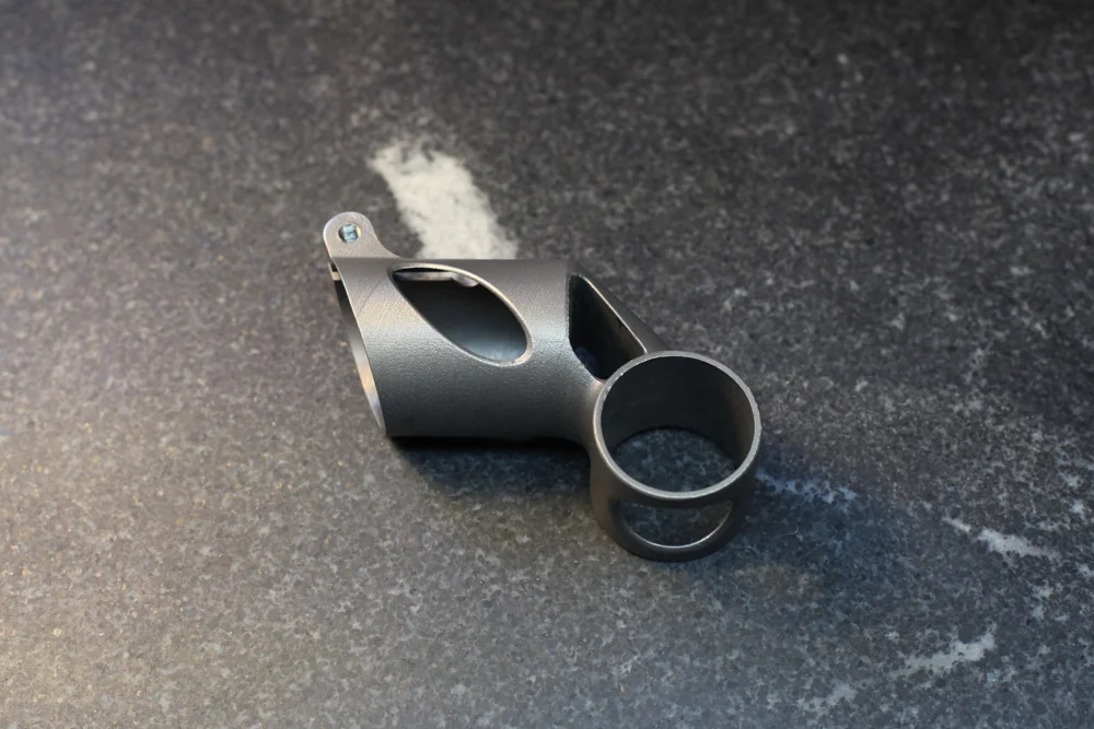
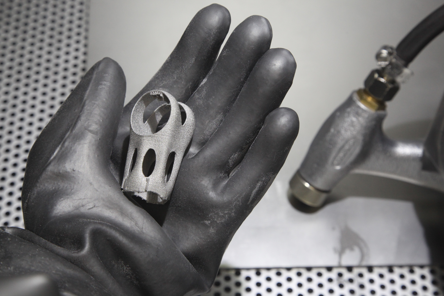
Regardless, my part could be further optimized. What I’ve done to date was prove a basic concept: That metal powder bed fusion can be used to make thin walled bicycle parts. Which, to be honest, isn’t a particularly surprising result; after all, metal powder bed fusion has been used by others to create all kinds of bike parts, including both road and mountain frames. 

The question is: Can I make it commercially viable?

Practical matters

With the current design and an order quantity of 10 pieces, the as-printed parts cost about $500 to make. Meanwhile, the most expensive commercially available seatmast topper I’m aware of (made by No22) costs $300, and the fanciest seatpost I’ve ever seen (made by AX Lightness) was under $600.

Now, there are a number of interesting things to note here. First, I’m able to buy in fairly low quantities. It’s not unreasonable for me to purchase parts in batches of 10, which is about as low as any non-stock commercial product in the world— and much lower than most products that involve forging, casting or CNC machining. If I can sell my part at a high end price point, then it wouldn’t take much cost reduction before I’ve got a reasonable margin — even with a strikingly low order volume. And there are a number of ways that I can reduce cost on this part:

  1. Even keeping the part’s design the same, I can reduce the cost by 25–40% by doubling the layer thickness. This will result in a rougher surface finish, but it’s possible that the difference will be acceptable.
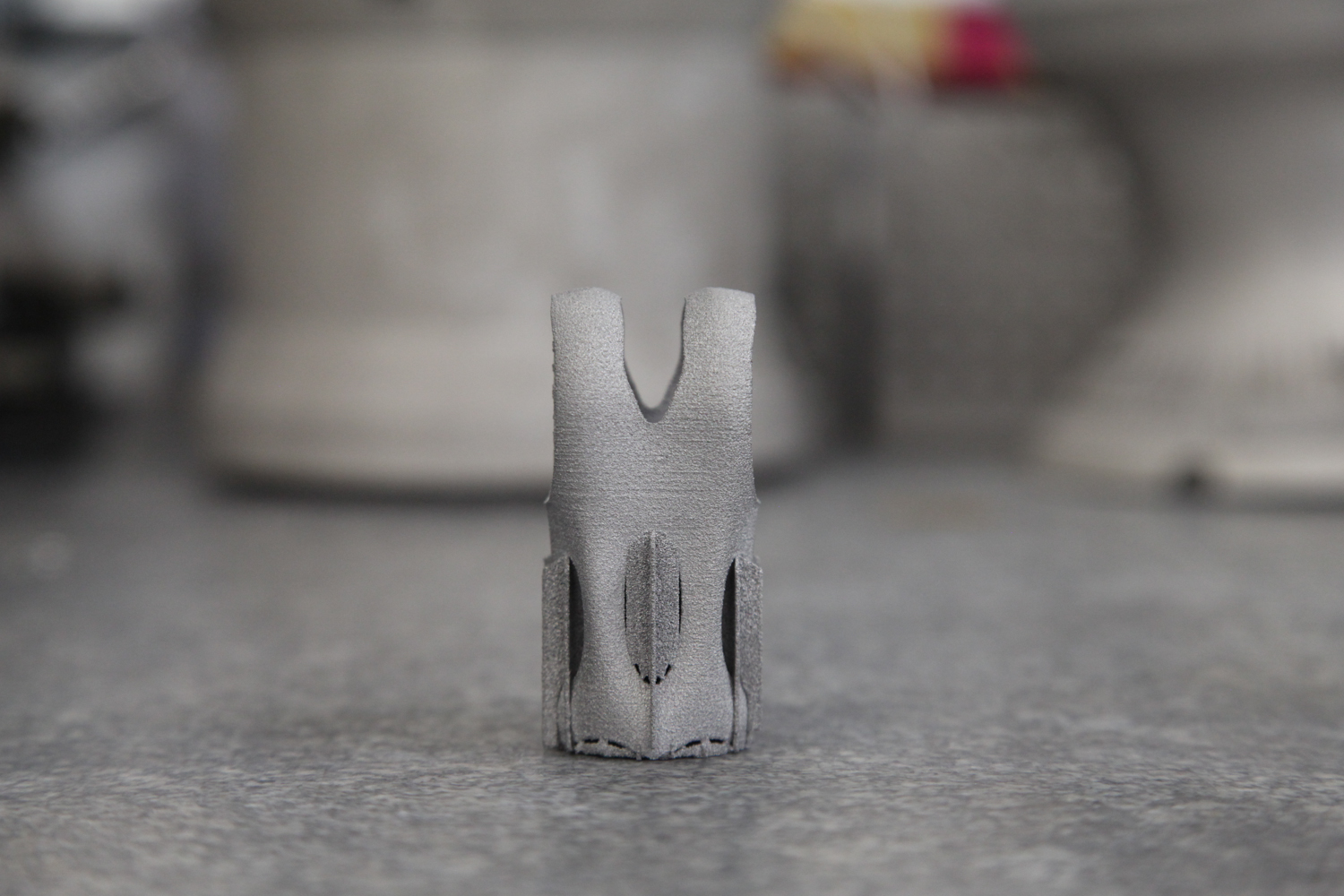
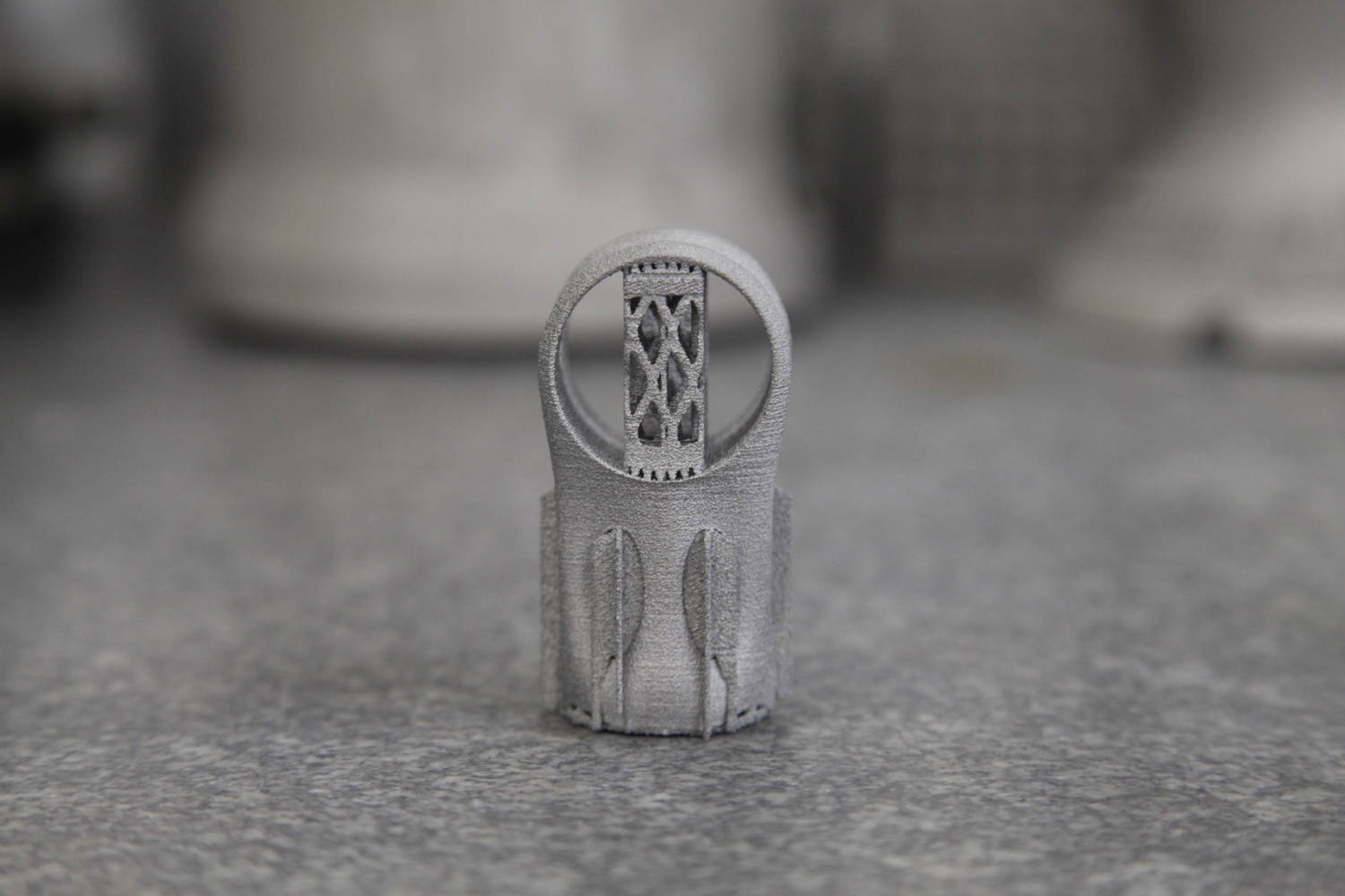
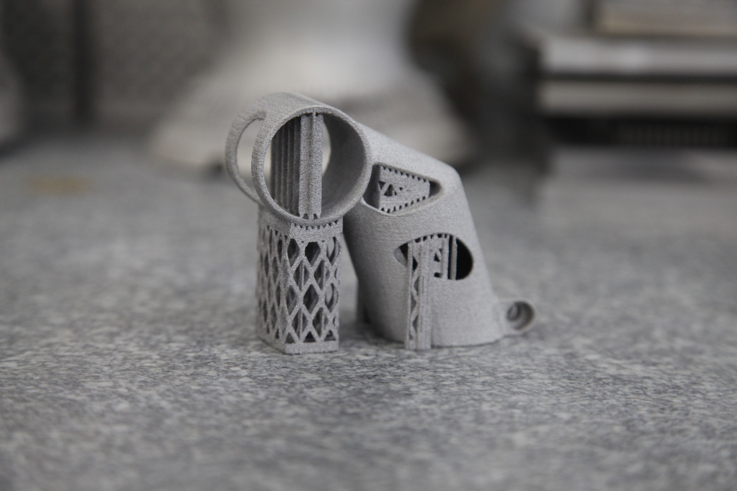
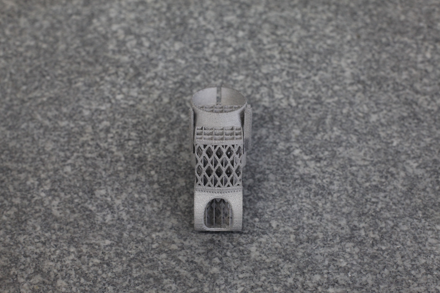
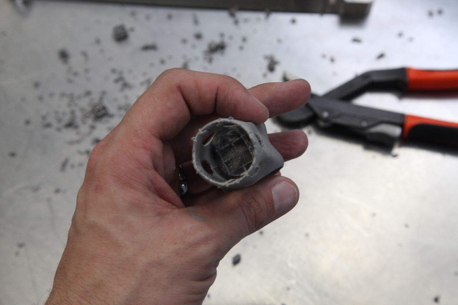
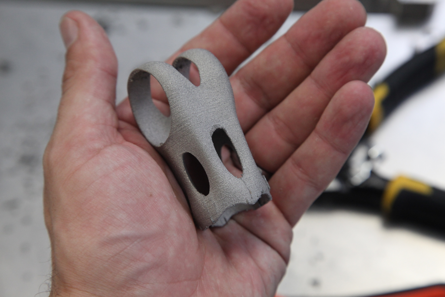
  2. A significant amount of time and effort can be saved by redesigning the underlying model so that the inner diameters need very little — or even zero — post processing. It’s unclear exactly how much work this will take, but it could reduce the price significantly.
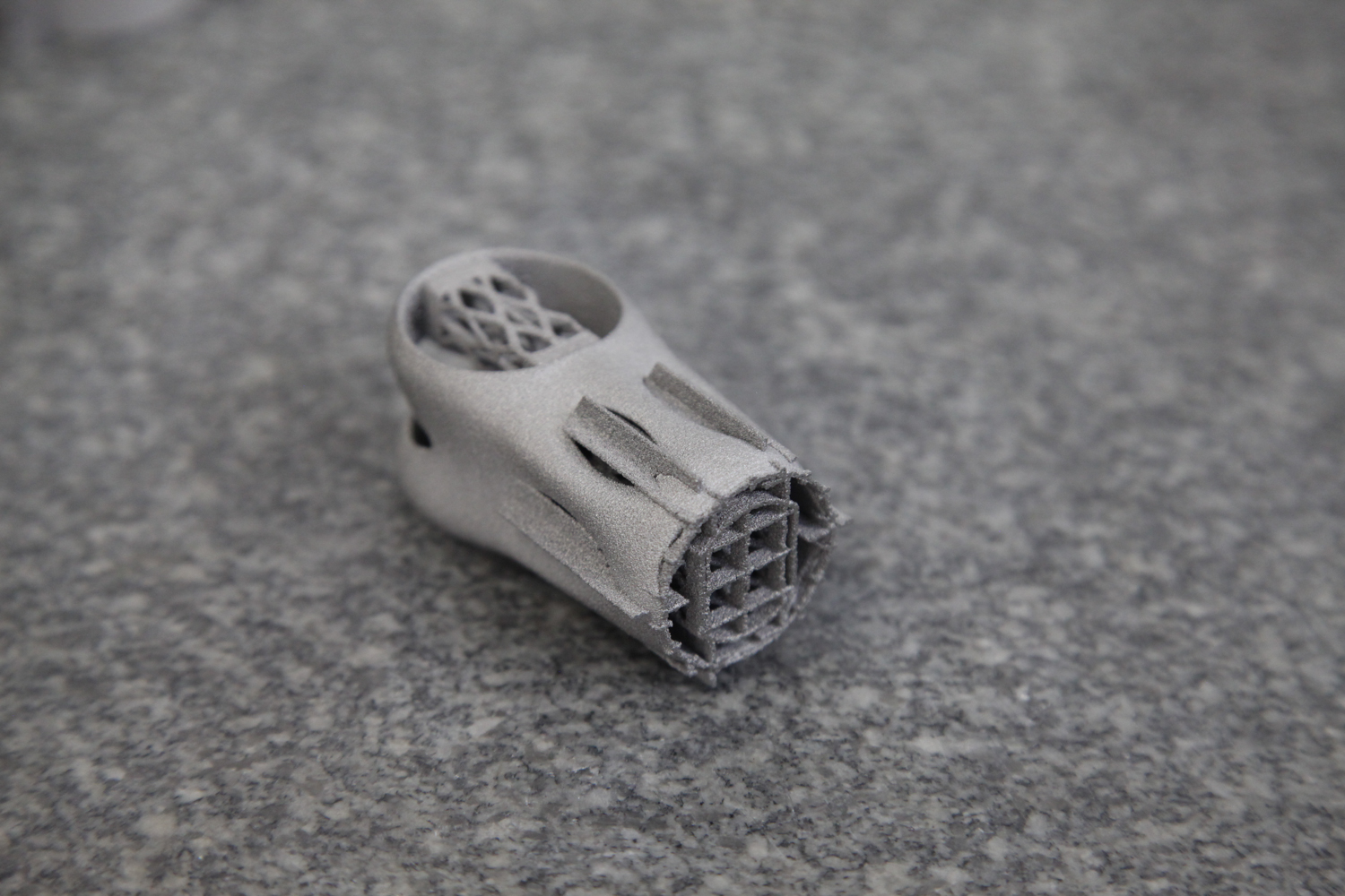
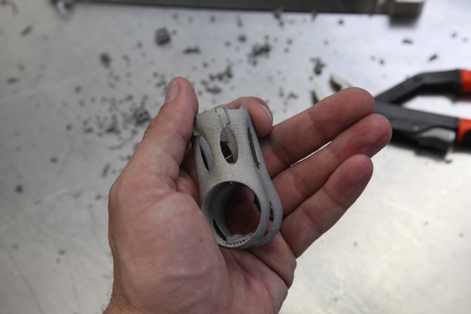
  3. Moreover, the entire part can be redesigned in order to reduce both the end mass *and* the amount of support structures necessary. Both of these have a big effect on price, though it will be time consuming to find an optimal design.

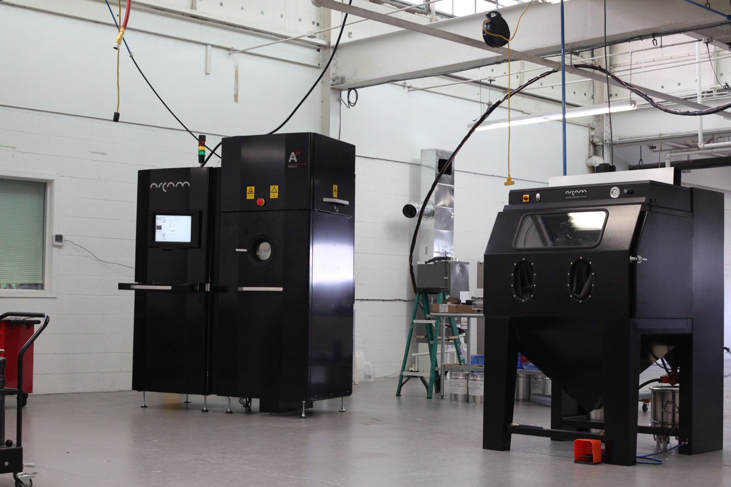
All of this assumes that I stick with a laser powered process. Electron beam melting (which I’ve been experimenting with) might reduce cost further, though the design constraints there are quite different. 

It’s also possible that while this part isn’t the absolute best application for additive manufacturing, there’s another place on high end bicycles where additive works better. This is key: The cost of this part is in the right order of magnitude as my goal. Any number of small changes — whether to the machine’s build parameters, the design, or the underlying cost of the technology — could easily put the numbers in my favor.

Industry observations

As I hope you would expect by now, a few things have jumped out to me in this past few months of work — some relating to longer term questions I have about the industry.

Manufacturing design

As a designer, having more — and earlier — access to support structure generation software is incredibly helpful. Today, countless design decisions are made on little more than a hunch; it’s not until much later that the ramifications of those decisions become evident. This leads to an inefficient design-for-manufacturing process, where it’s difficult for product designers and manufacturing engineers to communicate all of the nuance needed. Until professional grade design software (and here I’m looking at Autodesk, Dassault, Siemens, and PTC) allows these implications to be understood early on, this will be a big problem. In other words, I should be able to set build orientation and design support structures directly in my CAD modeling environment.

Documentation

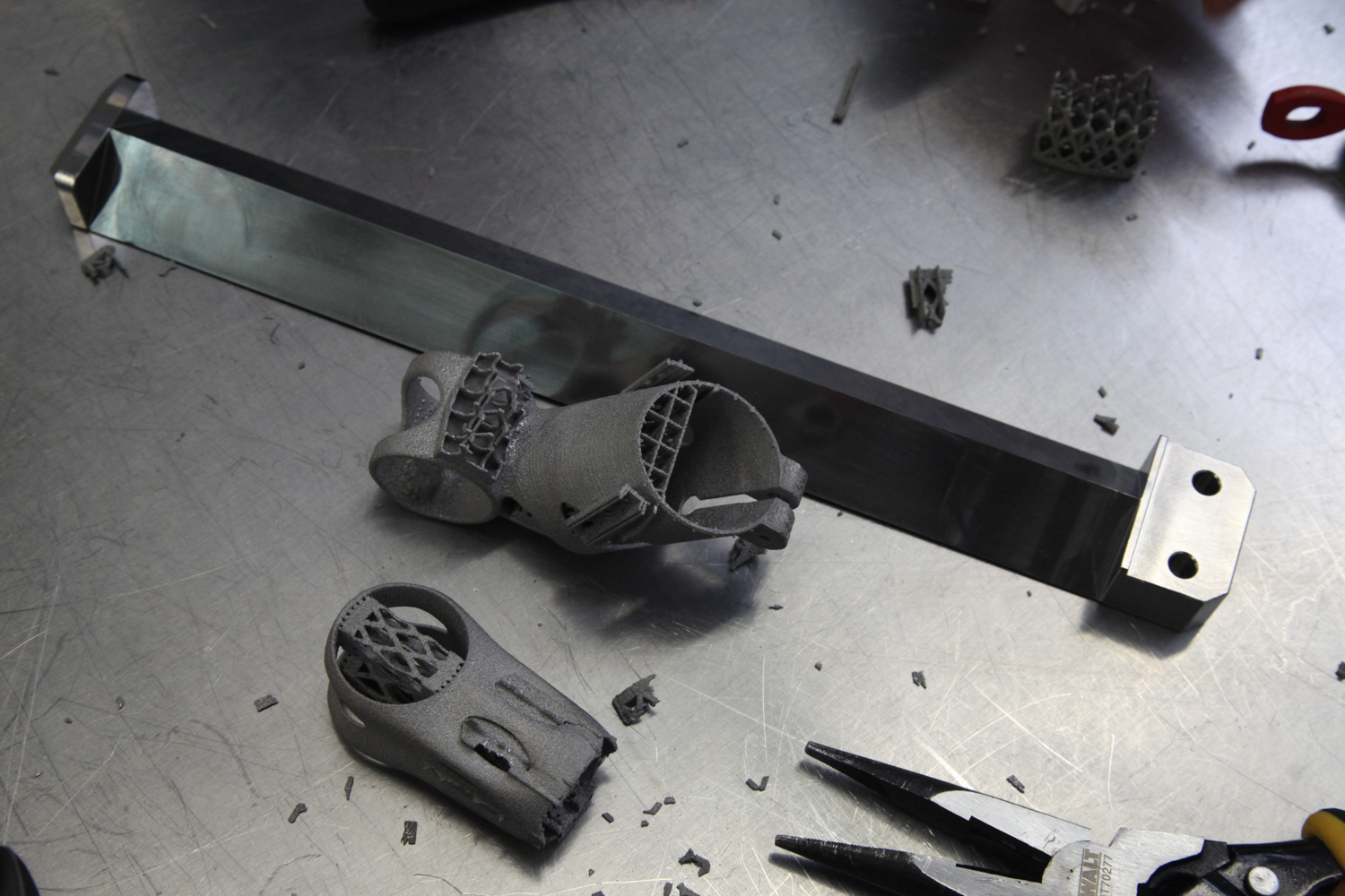
The designs that are loaded onto a metal 3D printer are often very different from the finished part, whether due to the addition of stock material to be removed subsequently (like my female threads), or the support structures necessary to hold the part on the build platform. But today’s modeling software generally only shows one state for each 3D model; those intermediate, near net shapes aren’t linked to the end design. This makes the design for manufacturing process even more disjointed and awkward, as it means that I’m never working on the same design documents as my manufacturing partner is. This communication structure is bound (cf. Conway’s Law) to be replicated in the end product, and the result is bad. To fix it, we need a new class of software that blends CAD (computer aided design) and CAM (computer aided manufacturing), allowing designers to understand a part’s production cycle with perfect clarity.

True design optimization

In the work I’ve described so far, I’ve relied exclusively on conventional volumetric and NURBS modeling techniques. But a new wave of design tools is out there — topology optimization and lattice generation, for instance — and they promise to create designs directly from functional requirements. Presumably these techniques would be just as applicable to my part as they are to the applications they’re already used on (mainly aerospace, biomedical, and other high tech applications). I’ve begun to explore this space, but the fact of the matter is that I’m not aware of a single consumer product today that was designed with these tools. My hope is that they both remove weight and make the part more visually appealing, but it could take a lot of work and some expensive (and experimental) software to find whether I’m correct.

Blatant editorializing: Gongkai for industrial additive manufacturing

Today, the viability of additive processes is totally opaque, producing a chilling effect on the creativity of both designers, service bureaus, and machine manufacturers. It’s my strong belief that that will only change by better understanding the efficiencies (and inefficiencies) of the additive manufacturing toolchain, and through my own work I hope to do just that.

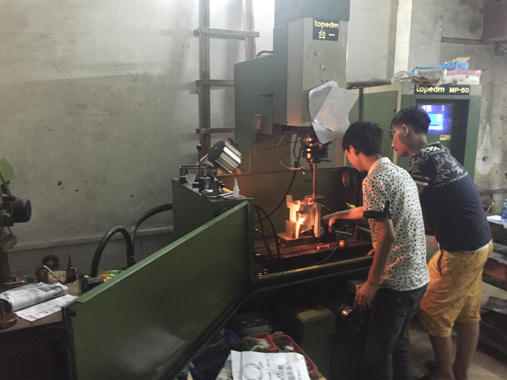
In a series (one, two) of recent blog posts, Bunnie Huang describes the way that Chinese electronics manufacturers have been able to drastically decrease the cost of consumer electronics. To me, they provide an example for how additive manufacturing could advance much more quickly:

My most striking impression was that Chinese entrepreneurs had relatively unfettered access to cutting-edge technology, enabling start-ups to innovate while bootstrapping. Meanwhile, Western entrepreneurs often find themselves trapped in a spiderweb of IP frameworks, spending more money on lawyers than on tooling. Further investigation taught me that the Chinese have a parallel system of traditions and ethics around sharing IP, which lead me to coin the term “gongkai”… this copying isn’t a one-way flow of value, as it would be in the case of copied movies or music. Rather, these documents are the knowledge base needed to build a phone using the copyright owner’s chips, and as such, this sharing of documents helps to promote the sales of their chips. There is ultimately, if you will, a quid-pro-quo between the copyright holders and the copiers.

It would be an understatement to say that industrial additive manufacturing hasn’t adopted gongkai. Today, trade secrets & patents are the name of the game; the access I’ve been permitted (by Layerwise, DRT Medical-Morris, and countless other friends across the industry) is rarely afforded to others. It’s my feeling that this is bad, both for the technology as a whole and for the long term interest of individual players within it.

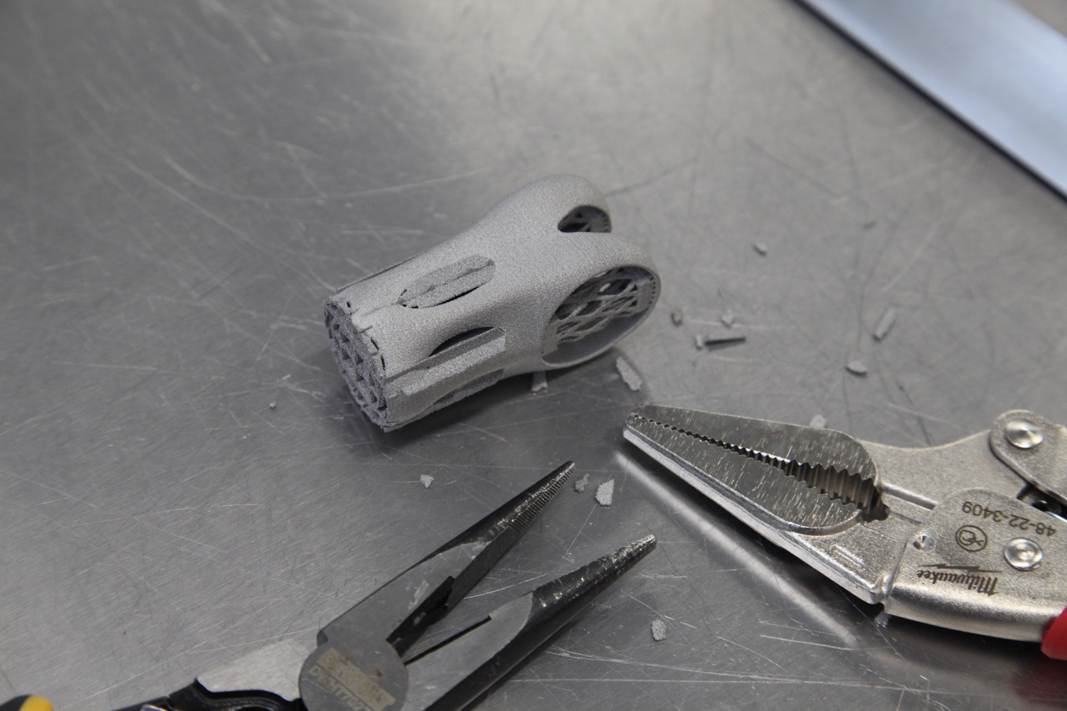
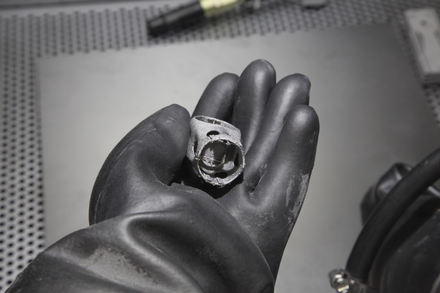
For instance: Anyone with experience could, given a part geometry and its build orientation, surmise more or less what the support structures will look like. If you have a physical part in hand, it’s even easier to reverse engineer; a part’s layer boundaries reveal its build orientation, and even with careful cleanup it’s generally possible to tell which surfaces have had support structures removed from them. In short, manufacturing forensics is, with enough experience and care, fairly reliable. And yet orientation and support structure setups are almost always treated as closely guarded secrets.

With so much uncertainty in industrial additive manufacturing today, firms are caught in something of a prisoner’s dilemma; their protective IP strategies prevent the industry from moving forward in the way that everyone ultimately wants it to. 

All around the world, intelligent, hardworking people trying to solve the most basic problems in additive manufacturing. Everyone in the industry knows what these are, and all of the major players are fighting tooth and nail to solve them first. And though it seems a long way off, I think most of them genuinely believe that they’ll see fully automated orientation & support structure generation within the next decade or two.

But today, the process of printing a part is decidedly hands-on; expertise is critical. “The people who are good at this stuff are good at it because they’ve been doing it for eight years,” one industry veteran told me recently. For sure, this industry is full of valuable intellectual property. But in most cases, *craftsmanship* is central to most firms’ bottom lines — and it is protected at all expense.

I believe that industrial additive manufacturing needs far, far more knowledge sharing. We need an environment closer to the one that Bunnie describes: 

We need “a ‘network’ view of IP and ownership: the far-sight necessary to create good ideas and innovations is attained by standing on the shoulders of others, and as such there [should be] a network of people who trade these ideas as favors among each other.”

In the coming moths, I’m looking forward to working on just that.

This post is just one in a series, and I remain convinced of what I’m working towards. With any luck — and more open collaboration with intelligent, committed people in the industry — I’ll have more to report soon :)

Thanks to

First, thanks to Martijn Vanloffelt and Tom De Bruyne, of Layerwise, for both their hard work and their willingness to help me understand how they work.

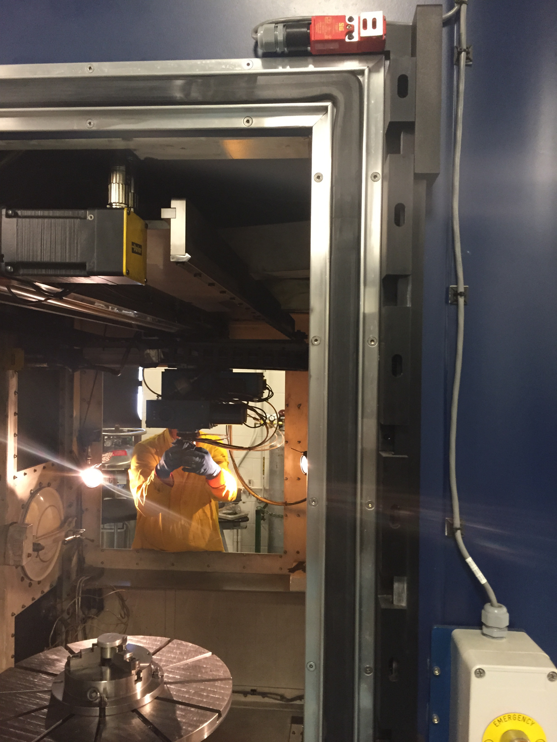
Second, thanks to Marcus Schröder, of EFBE, for both his hard work and the enthusiasm he had for testing my part — and discussing at length the testing & engineering cycle he sees in the industry today.

Thanks also to Dave Bartosik, of DRT Medical-Morris, and Dustin Lindley, of UCRI. Their continued technical help has been an incredible asset, without which I may never have begun this project.

Thanks also to Clay Parker Jones and Bradley Rothenberg for reading early versions of this piece.

A few thoughts sent from China

Added on by Spencer Wright.

After a week traveling in Hong Kong, Shenzhen, and Dongguan for The Public Radio, I wanted to post a few quick thoughts on China and other related stuff. There will be more to come (photos + detailed descriptions of the places we visited), but here are the things that struck me most prominently during the trip.

Reasons to pay attention to China

I feel like if you need reasons to pay attention then you're already lost. Nonetheless:

  1. I like China a *lot.* The places we visited ranged from visually striking (mostly in their scale & the obvious rate of change that they're going through) to absolutely beautiful; the people we visited and talked to expressed more raw enthusiasm and interest than almost anyone I know; and the culture is just fucking *cool.* I really enjoy being here, and can't wait to explore the vast expanse of geography and culture that I've so far had only fleeting exposure to.
  2. Even if you don't *enjoy* it as I do, I don't understand how anyone can be *disinterested* in China. It's an absolutely fascinating place, and is historically unique in that it has highly mature cultural systems (which are significantly older and more well documented than anything in Europe, for instance), *and* is at the same time navigating a totally unprecedented period of both cultural and technological development and turnover. Add to that the pure drama of the past century or two of Chinese history (I'm shocked that so many Westerners lack even a baseline understanding of, for instance, the Cultural Revolution), and you have what I believe to be the most compelling and spectacular narrative of our time. Even if you don't *like* it, I'd be shocked if every single person who reads this can't find a wealth of fascinating storylines to dive into here.
  3. IT'S BLOWING UP. This country is doing totally mind blowing things right now, and there's little doubt in my mind that the 21st century will see its total dominance of so many of the things (global economic systems; technological prowess; cultural influence) that the West has controlled so well over the past few hundred years. To not make a good faith effort to gain at least a basic understanding of Chinese history, culture, and growth would be to do a complete disservice to one's own future. It offends and saddens me to see my contemporaries doing just that.

A few observations about Chinese culture

  • I've remarked on this before (in particular after visiting Taiwan), but the way that today's Chinese cities (to be specific, as I've visited only a few: Shanghai, Suzhuo, Shenzhen, Dongguan, and Hong Kong) integrate the many modes of life is both impressive and heartwarming to me. In the US, we vilified Robert Moses while never really heeding Jane Jacobs' ideas: our cities still separate commercial from residential spaces, and real manufacturing & logistics is rarely to be seen. But in my experience in China, these three aspects of human activity often exist in close proximity. Moreover, they're often done *as a family;* in the small manufacturing shops we saw in Shenzhen and Dongguan, it was evident that child care is no more complicated than... having your kids hang out while you work. It's possible that I'm a rare case, but this is very appealing to me.
  • I'll write a longer thing about this sometime, but "distributed manufacturing" totally exists here - and it has *nothing* to do with 3D printing. Anyone who talks about how 3D printing is making it so that "regular" people can make stuff (a popular line in both the American press and VC communities) is full of shit, and the reality is that they probably don't understand even the most basic realities of what "manufacturing" looks like.
  • It continues to surprise me how shocked Chinese people are when I have anything more than a passing interest in their culture, language, and customs. Admittedly, it's fair to say that in these things I'm an outlier among my contemporaries; still, the totality of my efforts amount to little more than being comfortable using chopsticks, being open to weird and/or spicy food, and being able to say "I cannot speak the Chinese language" in Mandarin. Meanwhile, most of the Chinese people I meet are often totally fluent in English, eat McDonalds and KFC, have at least some awareness of American culture, and own clothes and accessories made by (or at least copied from) trendy Western brands. I talked to my friend Dan Hui about this, and he pointed out that many Chinese people assume that learning about Chinese culture is as difficult in the US as learning about American culture is in China. Moreover, many of the people who I've come into contact with here are business contacts, and the stereotype of an American businessman isn't exactly someone who goes out of their way to eat random street food. Nonetheless, I continue to encounter people here who are cultured, outgoing, and genuinely interested - and their default assumption is that I am none of those.
  • Everywhere I go in China, I'm struck with a willingness to accept short term discomfort with the promise of long term, lasting growth. This is something that the US (and Europe, for that matter) is really, really shitty about. A jackhammer in the morning; a closed sidewalk; ongoing construction on the BQE - all of these things are treated as unjust intrusions into civilized life. Never mind the NIMBYism that prevents the kind of municipal and regional scale infrastructure improvements going on in China today - in the US, those sorts of things went on a path parallel to Robert Moses' reputation. I'll admit, of course, that the tradeoffs between growth and stability are difficult to navigate. But it's truly inspiring to see a collective effort across Chinese society to *get the next hundred years right,* and I can't help but feel that Western conservatism isn't helping us compete.

General purpose travel notes

  • I bring a handkerchief or bandana everywhere I go. Napkins aren't really a thing, and it's nice to have something to wipe off with.
  • I don't know about you, but drinking outdoors, in public - especially in a subtropical climate - is one of my favorite things. Neither mainland China nor Taiwan have open container laws, and I take great pleasure at stopping in at a 7-Eleven or street stall and cracking open a Tsingtao as I explore a neighborhood on foot. The shocking thing is that nobody else - local or tourist - seems to be doing the same thing. Their loss.
  • WeChat is a really, really great app. I think it'd be great if more people in the US used it.
  • Most of the upscale (ish) hotels we stayed at had "gratuities" sections on their bills, but in general tipping is not a thing here. Which is fucking great, and I can't understand why the US won't follow suit.

Thanks *so* much to Dragon Innovation, who helped us plan & manage our trip - and to my friend Dan Hui, who was an excellent tour guide in Hong Kong & point of reference for our whole trip.

Planning for post processing

Added on by Spencer Wright.

The other day I got an email update from Rob Oliver, a machinist in Brooklyn who's helping me post process the EBM printed titanium parts that I got from Addaero recently. There's still a bunch of work to be done, but I wanted to write a bit about how we're thinking of the manufacturing plan - and the constraints that we're facing in the process.

While electron beam melting tends to produce much lower internal stress than laser powder bed fusion does, it's still a decidedly near net shape process. In further iterations I hope to get the as-printed part much closer to the final dimensions, but at this stage the parts I have deviate significantly from the intended tolerances. Specifically, most outer dimensions seem to have grown, most inner dimensions seem to have shrunk, and there are a number of locations where support structures have left unacceptable surface finishes.

My main focus right now is getting both inner diameters to within .006" of their designed size. It's difficult to get a reliable measurement of where they are now (due mostly to surface finish, and the presence of leftover support material), but they both appear to be about .040" undersized. In addition, I suspect that the shorter cylinder is slighly ovalized - though not to the extent that it'll be an issue in the end.

Although there are other conceivable options, the most obvious way to get the IDs within tolerance is milling. By using either a CNC toolpath on an end mill, or a boring bar on a conventional mill, it should be very easy to get well within .006" of nominal dimensions on both areas of the part. However, the issue of fixturing is nontrivial. I designed this part with T-splines, and its outer surfaces aren't orthogonal at all. As a result, we'll need custom tooling to hold the parts in a milling vise.

As an aside: Anyone who says that additive manufacturing eliminates the need for custom tooling has no idea what they're talking about. 

In order to securely fixture this part, Rob is machining its negative into a set of aluminum blocks, which can then be clamped securely into a milling machine vise. This technique (which I'll refer to here as "soft jaws," although technically what we're making is more of a coped fixturing block) is used extensively in subtractive manufacturing to hold irregularly shaped parts. 

The process of making soft jaws is relatively straightforward, but designing them for this part is somewhat complicated by the dimensional variation that EBM produces. Put simply, feature sizes in EBM parts tend to deviate from the design in the X and Y axes, but stay relatively true to size in the Z. That's because the Z axis is at least partly controlled by the Z stage drive system; the powder bed is lowered a predictable amount with each new layer, keeping features in the Z close to their designed dimensions. But in the X and Y, deviations in feature size are partly driven by the electron beam diameter, and partly driven by the distance that the feature is from the center of the build platform. 

As a result, my part has grown anisotropically, and Rob will need (to some extent or another; soft jaws tend to be somewhat forgiving) to compensate for the as-printed dimensions differently in the XY plane than he does in the Z.

In the end, though, the most practical way of determining the final dimensions of the soft jaws is to make a set, test them on the as-printed part, and iterate as necessary. It's conceivable that the first try will work, and it's also possible that if we make the negative a bit too big in all directions, we could use a piece of soft material (for instance, blue tape) to take up the gap.

It's also worth noting that there's an alternative path that I decided *not* to take. A common way to make parts - both with additive manufacturing and conventional - is to design fixturing features into an intermediate stage of the part. These can then be used to hold the part while secondary operations are performed; they can then be removed in a subsequent step. I considered this option, but find it undesirable for the simple reason that it would likely result in more post processing steps. Worse yet, it would probably require the surface of the part to be blended where the fixturing element had been removed, which would be either labor intensive, or unattractive, or both.

Regardless, we should have the first iteration of our soft jaws machined shortly. Expect updates!

My secret Manufacturing master plan

Added on by Spencer Wright.

Background: My day job is directing Undercurrent's strategy work with General Electric, but on the side I spend my time researching the state of the art in manufacturing - specifically, industrial 3D printing. I've written before about my approach to some of this work, but want to lay out here the way I see it fitting into my career.

As you'll know from my blog (cf. one, two), a primary focus of mine is developing a line of high end metal 3D printed bicycle parts. However, it might not be clear that that's just one step in finding specific applications where 3D printed production parts make commercial sense. In the end, the purpose of my work is to help expedite the transition toward a more fluid, transparent, and efficient mode of product design, manufacturing, and distribution - one which properly accounts for its own externalities, and allows for rapid integration of feedback across and throughout a part's life cycle.

I should be made clear that my long term focus isn't specific to additive. Every manufacturing method has a purpose, and any claim that 3D printing is going to unseat other methods should be examined critically. I want product designers have perfect transparency into how a given process will affect cost and function, and to be able to tune their design such that it's well matched for the resources at their disposal - and the end user's needs. 

I do believe, however, that additive manufacturing offers a unique and historical opportunity. Partly because of the fact that 3D printed parts always begin as 3D models - and partly, to be frank, because of its sex appeal - additive has encouraged a new wave of people to people to work in an industry (manufacturing) that was due for a radical change. And while the effect of their naïveté is often to simply create churn, in the end I believe that manufacturing will benefit greatly from the influx of new ideas and working styles.

In order to harness this opportunity, I'm focused on developing the most compelling possible use case for the technologies at play today. For metal 3D printing to reach industrial maturity, designers need to understand its limitations - and how to best exploit its strengths. So I have begun my research with metal powder bed fusion, which is currently the 3D printing process best suited for industrial use. I'm developing parts which make good use of 3D printing's strengths (lightweight, low production volume, smaller than a breadbox), and an industry which prizes the traits that additive manufacturing is best suited for (has short sales cycles, rewards innovative design, benefits from customization).

Today, developing metal 3D printed parts is an expensive process, and it's difficult to estimate how difficult a project will be. So to begin, an easy place for me to provide value has been to explain (in sometimes painstaking detail) the experience I've had over the past year and a half. Because there's so little public information about the realities of  metal powder bed fusion, writing on that subject has allowed me to boost my profile quickly. 

But more importantly, it has encouraged other people who are working on similar problems to offer collaborations. This has helped me twofold: First, it has in many cases resulted in decreased costs on my end, as the people and companies that I'm collaborating with have given me prototype parts in exchange for me writing long, in-depth descriptions of what they do. But even more significantly, these collaborations have given me unique opportunities to see past the marketing and sales messages and talk directly to the engineers who know the state of metal powder bed fusion best. This has allowed me to advance my own level of knowledge much more quickly than I otherwise could have, and has given me access to people who I can now turn to when I'm stuck.

To be sure, I have a *ton* to learn - and ultimately I'll never know as much as the seasoned professionals who I'm working with now. But between the hands on experience that I'm getting by building bike parts, and the access I now have to the most advanced research organizations in the world, I find myself in an ideal position to identify what aspects of today's manufacturing ecosystem most desperately need fixing - and who the most well positioned players are today. And that, plus the (I hope) sincerity, honesty, and intelligence that I've employed in writing about my own development process, puts me in a position to be a key part of whatever team ends up fixing them. 

So, in short, the master plan is:

  1. Build compelling 3D printed products.
  2. Use the exposure I get from that process to learn as much as possible about the industry.
  3. Use that knowledge to identify the biggest problems today, and find out who's best positioned to fix them.
  4. Form like Voltron with those people, and together make sustaining and powerful changes to the way that the product development life cycle works.

Don't tell anyone.


ps - Hat tip to Elon Musk, whose strategy (and how he communicates it) rocks.
pps - I also explicitly want to bring more advanced manufacturing development to New York City, which I believe is the best place in the world to do serious work.

Notes from Tesla's Fremont factory

Added on by Spencer Wright.

Today I had the pleasure of visiting Tesla's Fremont factory, where every single Model S is built. While they don't allow photos on the tour, I did take this pano to prove that I'm not fabricating the whole thing (but seriously though, a Google Image search does a decent job at showing you what it looks like inside):

IMG_1450.JPG

Anyway, a couple of thoughts came to me on the tour, and I wanted to share them:

  1. First of all, the whole place is an information overload. It's noisy (not at all unbearable, but still), and the tour is a whirlwind - the whole thing took just over an hour. Moreover, the entire building is filled with visual clutter. It's all stunningly beautiful, but there's just so much going on, and it's nearly impossible to see, analyze, and understand what you're looking at, what's being done to it, and which direction it's headed in the assembly line, before the train of golf carts that you're being dragged around in speeds off to the next thing. This is not meant to be a criticism of either the tour or the factory itself, and I'm sure an automotive engineer would have an easier time soaking things in than I did, but for the majority of the tour I struggled.
  2. Lot of emphasis on sheet metal. Elon Musk loves his aluminum, and the tour itself is expressly directed towards the hydraulic presses that Tesla uses to turn rolls of aluminum sheet (from what the tour guide said, I suspect it's 16ga) into a car. 
  3. The tour also emphasized the economy that Musk/Tesla employs in building up their capabilities. The core story here is that American manufacturers (GM is called out by name, mostly due to the fact that they're the former owner of the NUMMI site, which you should learn about) don't want/need big equipment or industrial space in the US anymore, and so Tesla has been able to buy this stuff for a song. So the purchase of their largest hydraulic press (the biggest in North America); the decision to use a Lotus platform for the Roadster; Tesla's use of the factory itself; - all of these are described (not inaccurately) as shrewd financial decisions.
  4. Interestingly, the only other brand names that get shout-outs on the tour are all Robotics companies: Kuka, ABB, and Fanuc. That fact - combined with the legendary stuff (all apparently real) about many of these robots having X-Men names - and the fact that the tour also highlights the human craft that goes into a range of sexy (and not-so-sexy) features of their cars - gave me the distinct feeling that Tesla consciously makes their industrial automation efforts seem as anthropomorphic as possible.
  5. This has been reported before, and it's worth noting again: Tesla's current production is about 1,000 vehicles per week. In the NUMMI days, this same facility turned out about 6x that.
  6. One thing that I was somewhat surprised by: Towards the end of our tour, the guide paused to explicitly note Tesla's purpose: To help expedite the move from a mine-and-burn hydrocarbon economy towards a solar electric economy. To be sure, I personally find this statement to be the most compelling thing about Tesla/Musk, if not the most compelling thing about any public company in the world (if you haven't read Musk's Secret Tesla Motors Master Plan, I'd really implore you to do so). But to hear it called out on a factory tour, to an audience which was made up almost exclusively of Tesla owners (besides a Tesla employee who had brought their family, I believe I was the only person *not* picking up a Model S right after the tour), seemed downright canny. Which leads me to my real observation:

Tesla is not, first and foremost, a manufacturing company; to wax on about the factory tour would miss the point. Their focus is simple: Musk has a singular vision for how the global energy lifecycle should work, and Tesla is doing whatever's necessary to bring it to fruition. Tesla is an energy company, and they're a "we're doing this because we believe in it and goddammit nobody else will" company. Which is really admirable, and it pleased me to see them use their factory - which, in spite of its relatively low throughput, is certainly a spectacle to behold - as a way to convert people to their mindset.

First EBM prints

Added on by Spencer Wright.

A few weeks ago I visited Addaero Manufacturing, one of the very few EBM (electron beam melting) service providers in the US. After my recent trials (and successes) with laser powder bed fusion, I wanted to try building parts with EBM. EBM is used extensively by aerospace and medical OEMs, but its penetration into the job shop world is way behind laser. Addaero, whose founders (Rich Merlino and Dave Hill) both worked at Pratt & Whitney before striking out on their own, is located just a few hours from New York City, and they were gracious enough to build two parts for me to evaluate the process.

I'll be writing up a longer post on the unique design considerations that EBM poses, but for now I wanted to share the pictures I took while there:

At this point, the parts Addaero made for me still need post processing before they can be assembled and tested. I'll be working on that over the coming weeks, and will update soon on my progress.

Things that are on my plate right now

Added on by Spencer Wright.

Mostly for my own benefit & the sake of catharsis, here are the things that are consuming my attention over the past & for the next few months:

  • Planning my own wedding in October.
  • Having fun this summer.
  • Getting more exercise.
  • Writing a long blog post on the seatmast topper that I had printed (DMLS) by Layerwise, and then tested by EFBe
  • Writing a long blog post on the seatpost that I had printed (EBM) by Addaero.
  • Digging more into McMaster-Carr's iOS app, and comparing it to Amazon's recently rebranded Business offering.
  • Planning a sourcing trip to Shenzhen, where Zach and I will investigate a significant redesign of The Public Radio's speaker & mechanical assembly.
  • Getting more hands-on experience with metal powder bed fusion machines. Because there are none in the New York metropolitan area, this inevitably means traveling for a few days to somewhere where I have a friend in the industry.
  • Doing a deeper dive into the variety of design tools that are cropping up for additive manufacturing. This includes getting better at T-splines (Autodesk Inventor), working with topology optimization software (SolidThinking Inspire; Frustum Cloudmesh), and doing some experimenting with lattice structure generation (with nTopology).
  • Doing a deeper dive into build preparation software, namely Materialise Magics.
  • Building myself a real desk, preferably with a proper toolchest integrated into it. I also want 2x24" displays, a proper Windows computer for 3D design, a new Mac for daily use, and a place for both a Wilton "bullet" vise and my 12"x18" granite surface plate.
  • Writing a presentation on metal 3D printing that covers both my experiences over the past two years (a case study), and my broader observations on the industry. 
  • Getting said presentation accepted to an industry conference (likely either AMUG, RAPID, or Inside 3D Printing).

There are a few more longer-term things, but this is a pretty good list for now.