Note: What follows here describes my early experiences designing and building metal 3D printed parts. Since this post was published, I've had a number of parts printed successfully; you can read more about the current state of this work in a recent update, here.
Last December, in an industrial park in Cincinnati, I watched as Dave Bartosik set up a build platform on an EOS M280. The part he was printing is one that I began designing a full fourteen months earlier, before I had any idea of the intricacies of metals 3D printing, nor the complexity in bringing an additively manufactured part from design to prototype.

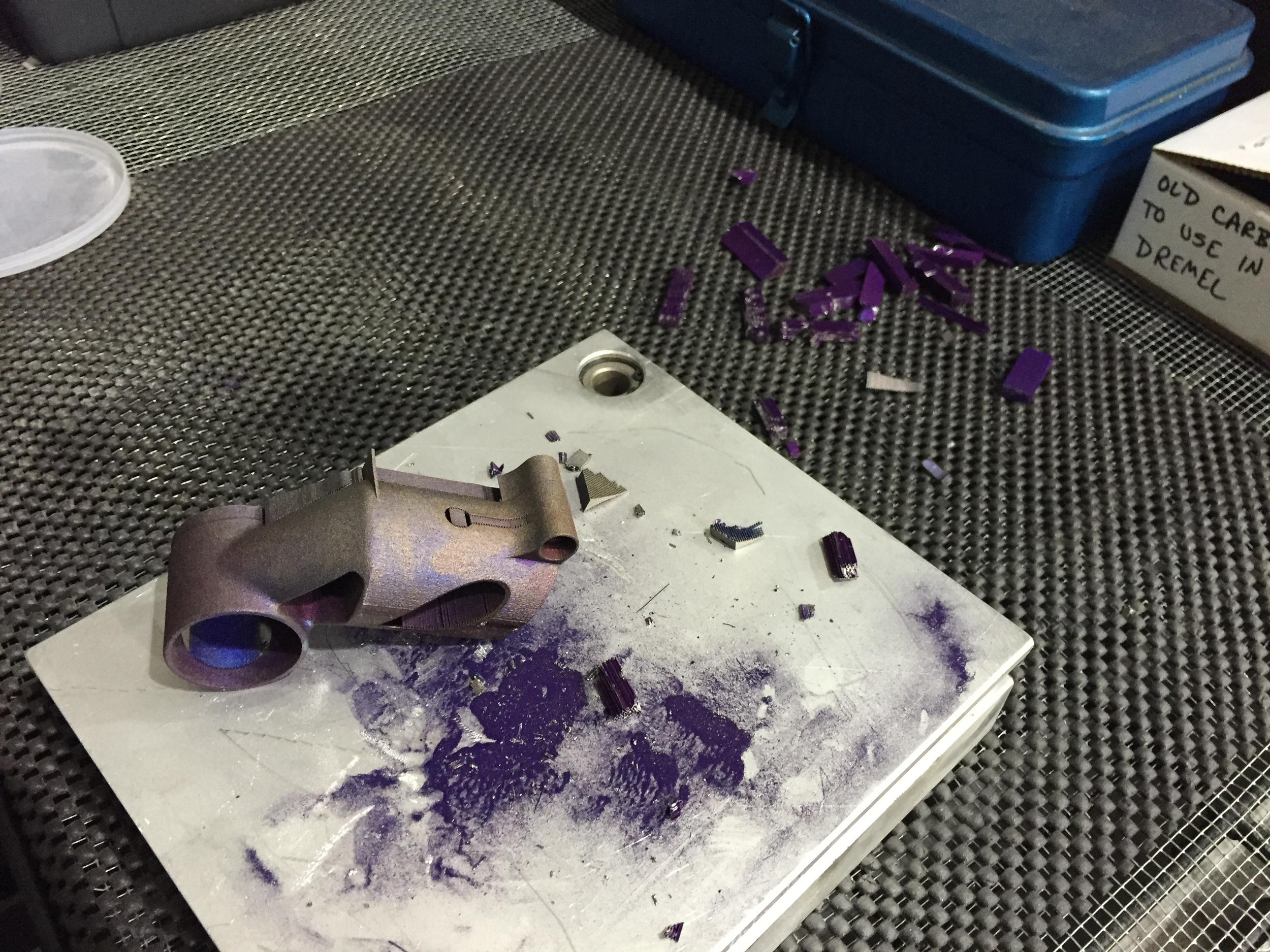
My part, being sintered from titanium 6/4 powder.
While the consumer 3D printing community has coalesced around openness, the industrial market tends to be opaque. Sure, anyone can design parts with free software. But the process of bringing those designs to life requires hundreds of engineering hours, tens of thousands of dollars worth of software, and millions of dollars worth of tooling — and even then, developing a single working prototype is a long and expensive process.
To many people, 3D printing offers a new manufacturing paradigm. It stands for rapid iteration, customization, and distributed fabrication. But today it’s arduous and costly, and the knowledge base needed to enter the market is concentrated in a select few people.
Here, I’ll share what I’ve learned about 3D printing titanium parts so far — and what other designers should expect out of the process as well.
A primer on 3D printing metal
Within the maker and startup communities, a 3D printer is essentially an extremely accurate, robotic, hot glue gun, capable of making complex plastic parts within a few hours. For some people that means making functional models more quickly, and with less interaction with outside suppliers, than if they were machined or injection molded. For others it means a couple of desk trinkets, and for the really ambitious it provides a peek into a new way of bringing products to market, replete with on-demand, custom-to-order parts, produced just walking distance from where they’re used.
My background is in short-run manufacturing. I spent a few years building custom bicycle frames, and later ran a small prototyping shop, where I designed and tested robotic door assemblies on fast development cycles. When people talk about the need to iterate rapidly, I get it.
For five years, I worked in a shop that could make machined and welded parts on demand. There were always hiccups — prototype development is often more art than science — but in general we could, with a day’s notice and a bit of help from McMaster-Carr, take a 3D model and create a useable part from it. So when I think of 3D printing metal, I keep those kinds of capabilities (which are shared by easily thousands of shops around the US) in mind.
Metals parts are 3D printed in one of three ways:
Binder jetting, in which powdered metal is sprayed with glue to get it to stick together — and later infused with a second metal to make the bond permanent. The most common binder jet printers are made by ExOne. In general, binder jetting is used to create prototypes or parts that require low strength.
Directed energy deposition, in which metal is sprayed or fed at a part — and melted to that part by electric arcs or lasers upon contact. DED machines vary significantly; see DMG Mori and Sciaky for context. Directed energy deposition is even more niche than binder jetting; its application is mostly limited to repairs and very large aerospace parts.
Powder bed fusion, in which a bed of powdered metal is selectively fused (through sintering or melting) by a laser or electric arc. The most common powder bed fusion machine is probably the EOS M280, but Concept Laser, Arcam, and Renishaw (among others) all have their own offerings. Powder bed fusion has a variety of uses in both production and prototyping. It supports a wide range of materials (the most common being titanium, stainless steel, and cobalt-chrome) and with care can be used to create lightweight, strong, and highly customizable parts — just like mine. But the process is far from easy and is definitely expensive.
Though it’s used extensively within the aerospace, medical, and tool & die industries, there are no metal powder bed fusion products on the consumer market today. Which made me think: why not?
The powder bed fusion process
When it comes to machine design, humans aren’t nearly as creative as you might think. The basic model for milling machines has been around for more than a century, and despite the fact that the process has changed significantly during that time, the overall layout of industrial tooling today is much the same as has been since the Civil War. Today’s powder bed fusion machines are no exception: If you squint just right, they look a lot like CNC vertical mills.
Powder bed fusion machines consist of three core parts: The build platform, a material source & recoater, and a source of thermal energy.
During operation, a thin layer of powder is spread by the recoater blade across the build platform. Then the heat source — either a laser or an electron beam — scans across the build platform, melting powder selectively as it goes. Where the metal is melted, it fuses to the metal around it, creating a solid part. After one layer is scanned, the recoater blade spreads another layer of powder and the process repeats.
Printing things this way is slow; a part the size of a juice glass might take ten hours. The recoater takes a few seconds to spread each layer, and although the laser is moving incredibly fast, it takes some time to scan the cross section of a part line by line. Add to that the fact that each layer is about eight ten-thousands of an inch thick, and you see how anything larger than a thimble would take a long time to complete.
Although powder bed fusion can be done by both lasers and electron beams, lasers are far more common. Electron beam melting (EBM) is notoriously difficult to control, and although it has some advantages, EBM parts tend to have very coarse surfaces and require more post processing as a result. EBM also suffers from relatively low market penetration; by my count, there are fewer than five service providers for EBM in the US.
By comparison, laser sintering (which I’ll refer to as DMLS, for direct metal laser sintering, though that is technically an EOS trade name) is almost ubiquitous. I’m aware of about seventy US shops offering metal laser sintering in-house, and even consumer-facing providers like iMaterialse offer DMLS. And although EOS sells far more metal laser sintering machines than any of their competitors, the market is still competitive — and that competition is beneficial to the industry as a whole.
Within the aerospace industry, DMLS has a high adoption rate — at least in an R&D context. In fact, my collaborators and primary tour guides to the industry (Dave Bartosik and Dustin Lindley) both began their careers in additive at Morris Technologies, the aerospace DMLS giant that was acquired by GE Aviation in 2012. Between the two of them there’s about as much experience printing titanium parts as anyone else in the world.
But for all the work that has gone into understanding the properties of additively manufactured parts, the process is still very much in its infancy. It is not in any sense a mature technology, and the result is that each new part you design for DMLS — and, indeed, each new copy of the part that you print — is very much an experiment. Small variations in geometry and orientation can have huge effects on the way that a part prints. The laser’s scanning path is a closely studied subject, but much is not yet understood about it. Even keeping those variables constant, it’s often the case that building the same part on a different machine will produce very different results.
All of which is to say that DMLS is anything but plug-and-play. Even when a design has been optimized specifically for the process, it often takes dozens of tries before a functional part comes out of the printer. And the process of troubleshooting a failed build — even at the most advanced DMLS shops in the world — still involves a lot of trial and error.
Part constraints
In general, parts that benefit from 3D printing tend to have the following traits:
Benefit from weight reduction
Benefit from customization
Complex geometries
High inventory costs and/or long lead times
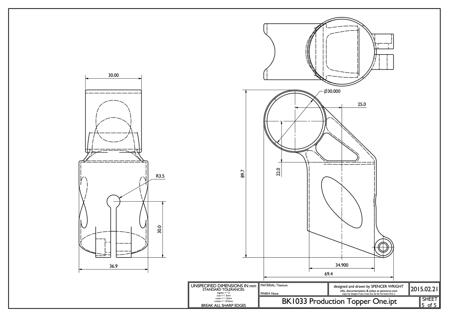
My seatmast topper, in full and half-section views. Note internal cavities in the center neck area.
The part I’m building is a seatmast topper for high end road bicycles. Cyclists want lightweight, custom parts. Custom bicycles are increasingly popular with consumers, and they carry high price tags and long lead times. Broadly, it’s my suspicion that more and more bicycle components will be produced on-demand through 3D printing — if only for the simple fact that within high end cycling, sexy sells.
At about 60 grams, my part is fairly lightweight. It’s also relatively small, and fits easily within nearly every DMLS machine’s build platform. And because of its function (seatmast toppers are used to hold a bicycle saddle onto the frame) its structural requirements are fairly predictable. These factors, plus the fact that seatmast toppers are easy for almost any cyclist to install on their own bike, make it a good candidate for 3D printing.
But that doesn’t mean it’s easy to print. My part consists of two cylinders, oriented 90° apart and joined together by a funneled neck. The part’s wall thicknesses fall between 1mm and 1.75mm — roughly .039"-.068". And it’s critical that these walls not vary much in thickness; if they end up just .010" thinner (for comparison, a sheet of paper is about .004" thick), the part could be unusable.
Harder yet, the inner diameters of both of the cylinders must be accurate and consistent. Again, variations of just .005" can have a big effect here — and if the cylinders end up with oval cross-sections, the part won’t work at all. And the titanium 6/4 that my part will be made of (which is named for its 6% aluminum, 4% vanadium content) is notoriously prone to built-in stresses, meaning that we’ll have to be very careful setting up the build parameters and support structures to prevent the part from turning into a pretzel during the process.
As with almost all 3D printed metal parts, mine will require some degree of post processing; at an absolute minimum, the clamp bolt threading will need to be tapped. But because of the physical tolerances listed above — and the mechanical and aesthetic properties of DMLS parts, which tend to be rough and unpredictable — it’s likely that extensive finishing will be required on both the inner and outer surfaces of the part.
In short, my part’s manufacturing process chain was always going to include some subtractive steps. There are many feature types that 3D printing simply isn’t intended for, and I knew going in that this part would require more than one process as a result. But until we picked a build orientation — and built parts that passed fit & finish tests — we wouldn’t know for sure what our total process chain would look like.
Build orientation
My prototyping partner, DRT Medical— Morris, prints titanium parts on an EOS M280 — the workhorse metal 3D printing machine for American job shops. Based on my research, EOS’s market penetration outmatches each of their competitors by five to one. As of November 2014, EOS only lists eighteen service-ready M280s in the US, but their data is clearly incomplete; I wouldn’t be surprised if the real number was triple that. Moreover, the vast majority of DMLS machines are purchased by OEMs, who use them for internal capacity only, and my suspicion is that the proportion of EOS machines behind closed doors is similarly large.
The M280's build platform measures 250mm (x) by 250mm (y), and is has a maximum build height of 325mm (z), including the build plate. My part is about 70mm long (x), 37mm deep (y), and 90mm tall (z).
A common misconception about 3D printing is that the unit cost doesn’t vary much with quantity — that printing one part is just as efficient as printing a thousand. Granted, 3D printing doesn’t require tooling per se, but non-recurring engineering costs are absolutely to be expected. In addition to the time spent determining an optimal build configuration, there are significant changeover costs when a DMLS machine operator goes from printing in, say, titanium to stainless steel — which some low-volume service providers might do on a weekly basis. Moreover, metal 3D printing providers don’t normally print multiple orders in one build. In other words, if I buy a titanium part at the same time as another customers does, they’ll usually run those orders in two separate builds — even if both parts might fit on the build platform at the same time.
The exact math is hard to reverse-engineer, but there are generally four variables that determine the cost of a DMLS part:
Finished part mass. There are two subcomponents here: Raw material cost, plus the time it takes the laser to sinter the part. Raw powder costs between $300 and $600 per kilogram. My part weighs about 60 grams, which puts the material cost in the neighborhood of $30. But that 60 grams will take about eight hours to sinter, and the cost of sintering time adds up quickly. As a rough guide, expect to spend on the order of $100–200 per hour for part build time.
Support structure mass. DMLS parts require solid support structures to tie them to the build platform, and those structures are made of the same metal powder that the part is. If your part has a lot of overhanging geometry or requires additional support structures for other reasons, you’ll pay for those (and the time it takes to sinter them) as well.
Part height. Across all types of manufacturing, capital expenses (tooling, etc.) are paid off over a period of years. In DMLS, part height correlates directly with time spent recoating the platform with new powder, and that in turn equates to a higher tooling cost that the supplier needs to pay off during your build. As a result, designers are incentivized to orient their parts as close to the build platform as possible, to reduce build height and hence reduce recoating time.
Number of parts per build. Because the setup and powder recoat time can be shared across multiple parts, buying in batches (when possible) will generally be less expensive than buying one-offs.
Build configuration 1: Part on it side. Ten parts, ~40 hours. Image courtesy DRT Medical — Morris
In my case, those last two factors act directly against each other. If I orient the part on its side, I can fit about 10 parts per platform, with a ~40 hour build time — about 4 hours apiece. But if I orient them vertically (upside-down ends up being more favorable), I can print 24 parts in a ~85 hour build — about 3.5 hours per part.
Build configuration 2: Part upside-down. 24 parts, ~85 hours. Image courtesy DRT Medical — Morris.
At this point, Dustin and I spent some time thinking through the manufacturing process chains for each of these configurations. It’s very likely that we’ll end up needing to machine the inner diameters of both of the part’s cylinders, and we wanted that process to be straightforward and involve as little custom tooling as possible (post processing DMLS parts often requires extensive custom tooling). As far as we could tell, build configuration 2 was going to be slightly easier — mostly because the long ID could be machined while the part was still on the build platform. But the difference was very difficult to quantify, and in the end our build orientation was determined for a much simpler reason: powder availability.
The DMLS powder market is, like most things in this industry, changing rapidly. Powdered metal is expensive to produce, and the particle size, shape, and consistency are critical to finished part characteristics. And while prices are going down rapidly (double digit percentages year-over-year, I’m told), service providers are still stuck with having a large chunk of money tied up in raw powder powder at any given moment. Add in lead times, and the fact that titanium powder isn’t particularly fun to handle, and you can see why job shops would only want to keep as much powder on hand as they absolutely need.
In the end, we ended up building my part on its side simply because DRT was getting towards the end of a batch of powder, and the taller orientation was going to require more than they had on hand. Which is possibly, given the small quantities these parts will probably be produced in, the right orientation anyway — and was a less expensive build to boot.

At this point, our goals were explicit: Determine the minimum amount of post processing necessary to produce a working part.
Stress & build failure
It’s critical to remember that 3D printed parts move as you print them. The same is the case with other manufacturing methods as well (injection molded parts shrink as they cool, machined parts warp as they’re cut, etc.), but DMLS creates extreme thermal gradients, and the net effect is that stresses are built into the part layer by layer.

Build orientation affects stresses in *huge* and unpredictable ways. See this paper, by Amanda Wu, a researcher at LLNL, for more.
Predicting built-in stresses is an incredibly difficult task, and is the topic of a lot of basic research. At the moment, the best we can hope is to analyze and understand the stresses that are built into parts once they’re complete; predicting them before they happen is still a long way off.
Despite the fact that stress prediction is very much a dark art, the correlation between laser sintering and welding is not a trivial one; many of the same principles apply to both. But when approaching a new part, it’s almost always the case that the best way to deal with potential problems is through trial and error — and then adding and removing support structures as necessary.
This is a key point: powder bed fusion involves welding your part to the machine while you build it. The build will definitely fail if the part lifts off the build platform (when this happens, the recoater blade strikes the part. In general it doesn’t damage the machine, but I’m told it can be… exciting), so a lot of effort goes into designing clever — and hopefully not too massive — solid and lattice support structures to keep the part where it’s supposed to be.
Even if the build itself doesn’t fail, internal stresses can still render it unusable. This is why most parts are stress relieved (a heat treatment process) after they’re built and before they’re removed from the build plate: doing so allows the crystalline structure to relax, preventing failure later.
Going into the build process, I was warned many times that cylinders oriented parallel to the build plate are notoriously difficult to build. The stress profile around the circumference of the cylinder will tend to vary widely, and the result is that you generally wind up with a big oval. But other than orient the part at a 45° angle to the platform (and risk ovalizing both cylinders), our options on this part were limited. So, we started as simply as possible, and iterated as needed.
Support structures & Iteration
Once the build is complete and the part is wire EDM cut off the plate, support structures are removed manually.
While I was in Cincinnati, I visited MicroTek Finishing — a major player in the metal 3D printing world. While there I spoke with Tim Bell, who related an anecdote about his time at Morris Technologies, the aerospace 3D printing giant that was acquired by GE in 2012. Tim was a product development leader at Morris, and he talked of a large bin that they had in their shop. It was called the Bin of Broken Dreams, and into it went an endless stream of failed parts.
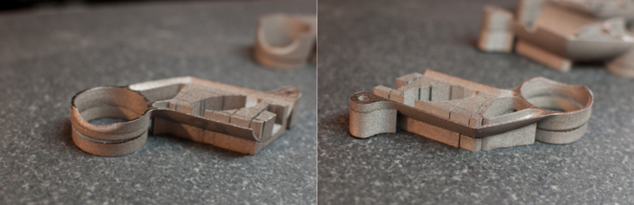
My part has now been printed in six different build configurations. We (and by we I mean Dave Bartosik, whose creativity and enthusiasm for getting the build to work was inspiring) added solid supports in a number of places, chasing built-in stresses around the part with each iteration. The latest prototype, although nonfunctional, is nevertheless a big improvement on the earlier builds — and the process has taught us a lot about the idiosyncrasies of my design.
To begin, Dave let Materialise Magics (the industry standard for support structure generation software) do its thing with no manual intervention. Magics generates mesh support structures, which are scanned every other layer of powder (solid regions of the part are scanned every single layer). As a result, they’re very easy to chip off the part — but don’t have the same strength that solid supports do. As internal stresses proved to be an issue, Dave added solid supports to keep the part undistorted and tied to the build platform.
Build 1
In this build, the part is laid on its side and supported only by mesh supports. The build failed at only 15.6mm in the z-direction, when the recoater jammed on the saddle clamp end of the part, which had lifted from the build platform.
Build 2
Here, the seatpost clamp cylinder is firmly fastened to the build plate. But the stresses just concentrated on the other end of the part, pulling the bolt boss and some of the front edge off of the platform at a height of 22.7mm.
Build 3
Both ends of the part — the saddle clamp and the bolt boss — are firmly anchored to the build platform. But this created a complex bending moment, pulling the center of the part upwards; the build failed at 22mm.
Build 4
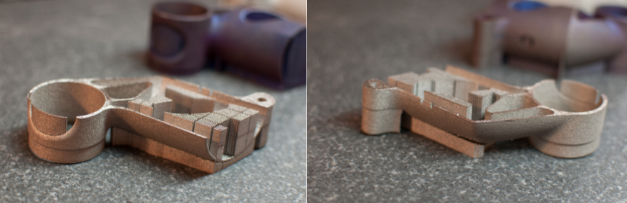
Here we’ve got solid supports on both the saddle clamp cylinder and the bolt boss, and added an additional solid rib to the middle of the part, tying it down there. This is the first build that completed; all of the others had failed midway through. We’re clearly getting closer, but the bottom of the part has distorted, pulling in and looking like a big “D”.
Build 5
To prevent the bottom of the part from distorting like in Build 4, we added a second solid rib. It helped, but only below the centerline of the cylinder; above that, the wall still pulled in.
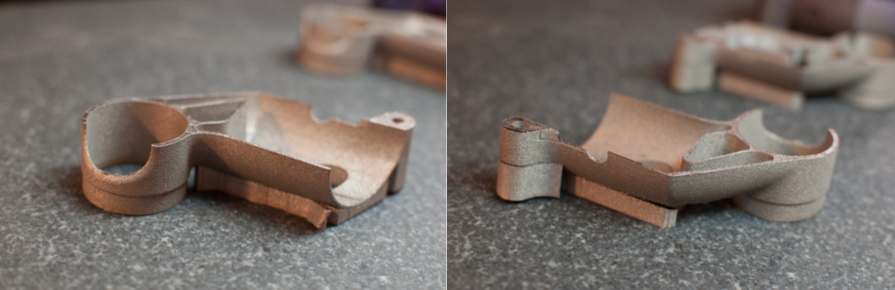
Build 6
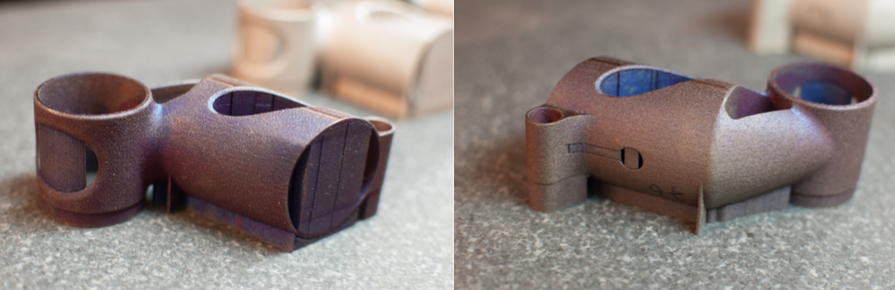
Build 6 finally produced a part that’s generally round and complete. This was achieved by extending the lower rib up the side of the part, giving external support to the entire bottom edge of the seatmast clamp cylinder. But although the top and bottom of the seatmast clamp are both basically round, the internal stresses still needed to go somewhere — and ended up bulging out the middle of the tube instead.
Throughout each of these builds, three things have remained consistent. First, the surface finish on the exterior of the part leaves much to be desired; it will definitely need to be finished in a separate step. Second, the surfaces that needed to be EDM cut from their solid supports (the saddle clamp and the bolt boss) are irregular, and will need to be smoothed into the rest of the part. Third, the internal diameters will almost definitely need to be post-processed by machining or EDM — even the saddle clamp, which overall had passable surface finish, was undersized by .020" — about four times the desired variance.
The net effect is that after six build iterations — each of which took almost two full days to set up, build, stress-relieve, and cut off of the build plate — we still don’t have a functional prototype to test.
Takeaways
What to take away from this? Well, prototyping is hard — but everyone knows that. My primary observations have more to do with the state of the industrial marketplace, and the maturity of metal 3D printing processes, than with the fact that we’ve now put six parts into our own bin of broken dreams.
File processing
As with consumer 3D printing, industrial 3D printers work exclusively from STL files. This produces a total break in the design-to-manufacture process. When I export an STL to send to a manufacturer, all of the underlying feature data is lost; all that’s left is a shape. This is drastically different from the conventional manufacturing world, where parts are regularly built directly from underlying design files.
Tolerances
For the vast majority of machined parts, any single dimension is expected to be accurate to within .005", regardless of size; in other words, a quarter-inch hole should be between .245" and .255", and a one-inch hole should be between .995" and 1.005". For a relatively small cost, designers can specify even tighter tolerances, and the means of achieving them are predictable and not overly complicated. But with additive, tolerances accumulate across the part at a rate .005" for every inch of distance. That’s fine if you’re building a one-inch part (whose dimensions will be between .995" and 1.005"), but larger parts can be problematic; a ten-inch part will be between 9.950" and 10.050" — a decidedly generous tolerance. Moreover, these tolerances don’t always stick; many of our early prototypes didn’t come close to meeting them. And when a part prints out of tolerance, the way to fix the problem is essentially to fiddle with the underlying design and then build it again.
Intellectual Property
Across the metal 3D printing industry, a stream of contract manufacturers told me the same thing. DMLS build processing is hard, they say. And the only way to maintain a competitive edge is to invest countless time and money into R&D — and then guard institutional knowledge vigilantly. On many occasions this is referred to as intellectual property, but the truth is that it’s closer to expertise; what’s being developed is craftsmanship, not patentable tools or methods. But whatever the name, the effect to designers is stifling. Regardless of manufacturing method, the design-to-manufacture process benefits from transparency; if a build fails, then I as a designer want to know the reason — and adjust my underlying design accordingly. Until the additive supply chain opens up to sharing its experience in the design-to-manufacture process, new DMLS products will be few and far between.
Undistributed Manufacturing
Today, 3D printing metal parts via a distributed supply chain is a myth, full stop. And while I’m as excited about that vision as the next guy, distributed manufacturing will continue to be a pipe dream for the foreseeable future. A distributed manufacturing ecosystem can only exist once there’s a robust network of suppliers capable of making parts repeatably. And while it’s my sincere feeling that the most hardworking, intelligent, and visionary people in manufacturing today are working in 3D printing, there simply isn’t currently a rich network of DMLS suppliers. For instance, the closest DMLS-equipped shop to New York City is a 200+ mile drive away. Meanwhile, MFG.com lists 68 machine shops within a 150-mile radius. If distributed 3D printing is to become a reality, the install base must increase by orders of magnitude — and the reliability and repeatability of the processes must improve dramatically as well.
In-Process Monitoring
In conventional manufacturing, parts are checked between operations to ensure that critical dimensions will be met. But the current generation of industrial 3D printers have little in the way of in-process monitoring, with the result that distortion isn’t detected until the build fails altogether. Although there are hints that this may be changing (B6 Sigma has announced some ambitious plans recently, and a lot of primary research is being done on the subject), the fact remains that until we’re measuring and analyzing the factors (thermal gradient, sound, vibration, etc.) that indicate build failure before it happens, trial-and-error will be the only way prototypes are developed.
The Process Chain
3D printing is very, very good for certain things. But it is not a one-stop process. For now and the foreseeable future, additive manufacturing will be a poor method of creating a number of important mechanical features, including many aspects of fastening and articulation. In addition, the surface quality of 3D printed parts will be unacceptable for anything requiring tailored aerodynamic features, and will be similarly poor for products whose fit and finish are of high value for aesthetic reasons. This is not to say that those aspects won’t improve; they will. But while I expect additive manufacturing to be an important part of the way parts are produced in the future, it’ll be a long time before it’s used to produce a wide range of products. And for those products which are well suited for 3D printing, their total manufacturing process chain will include subtractive tools (machining, honing, polishing, etc.) for the foreseeable future.
Next steps
My part has come a long way. Just having a physical prototype in hand makes a huge difference in understanding its benefits and drawbacks, and I continue to believe that with continued research and prototype development, I will find a way to make it commercially viable and attractive to high end cyclists.
But there’s much work to do. Moving forward, I see three primary directions to explore:
Keep the current build orientation, and continue to iterate on support structures as necessary.
At this point, it’s clear that we need to rethink the way we’ve been mitigating internal stresses. The external ribs are working somewhat, but even if we can add enough of them to make the build work, they leave ugly marks on the outside surface which require additional post-processing. Instead, I plan to experiment with reinforcing the inner diameter of the seatmast clamp cylinder. One thought is to create an internal lattice (like those that Frustum’s software creates), which would provide rigidity during the build and then be removed via machining afterwards.
Change the build orientation
Turning the part so that it’s upside-down on the build platform — with the seatmast clamp on the top — will offer significant advantages. The saddle clamp already has a thicker wall than the seatmast clamp, and is likely to resist distortion more easily. And with the seatmast clamp oriented in the z-axis, it’ll be in much less danger of distortion.
Try EBM
The electron beam melting process preheats the entire build platform to just under the melting point of titanium, and so generates much lower thermal gradients — and as a result less internal stress — than DMLS. EBM also generally requires fewer support structures, which is helpful for part cleanup. However, the surface quality and minimum feature size of EBM is significantly worse than DMLS, so EBM would probably require a longer overall process chain, with more material removal than DMLS would.
Regardless, I’ll be continuing this work over the coming months. These technologies are changing rapidly, and any ambitious product designer would be wise to pay close attention to their development. And only by experimenting with actual parts can anyone hope to keep up.
I believe that functional, engineered consumer products made by additive manufacturing are an inevitability. But as a product manager today the viability of metal 3D printing is totally opaque, and that will only change by careful study of the efficiencies (and inefficiencies) of the additive manufacturing toolchain.
Thanks
First, thanks to Dustin Lindley (of UCRI) and Dave Bartosik (of DRT—Morris), without whom all the cool stuff described above would have never happened. Thanks also to Greg Morris (who originally connected me with Dustin, Dave, and Chuck Hansford at DRT), to Clay Jones and Jordan Husney for their creative inspiration and infectious enthusiasm throughout the process, and to Clay Jones and Mike DiGiulio for reading early drafts.
Lastly, thanks to Undercurrent, which is providing critical funding for this project — and which I am proud to call home.
This article originally appeared in three parts on 3D Printing Industry.