Manufacturing guy-at-large.

Filtering by Tag: bikes

Stem prints

Added on by Spencer Wright.

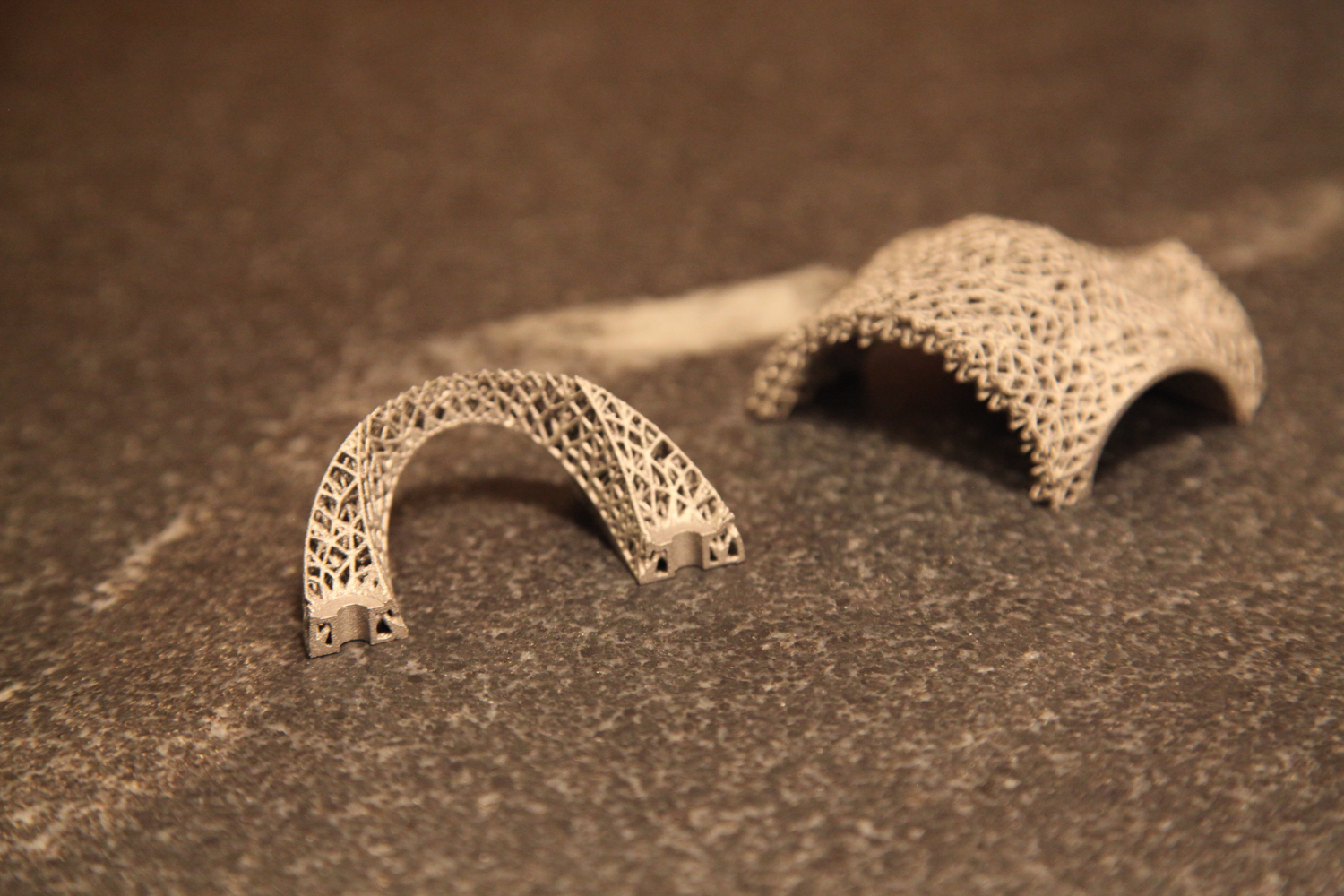
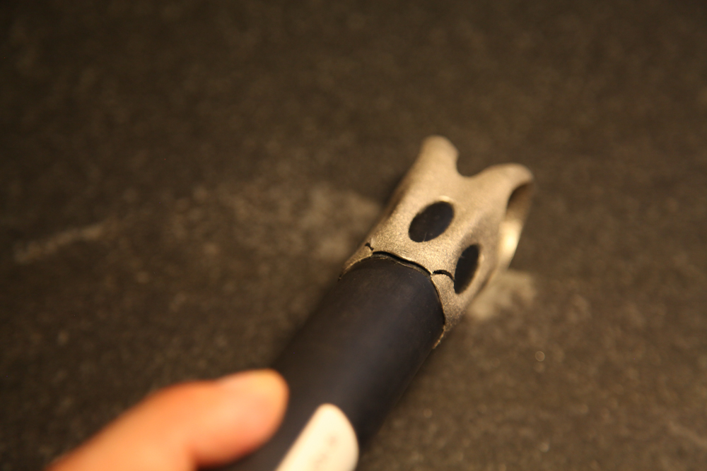
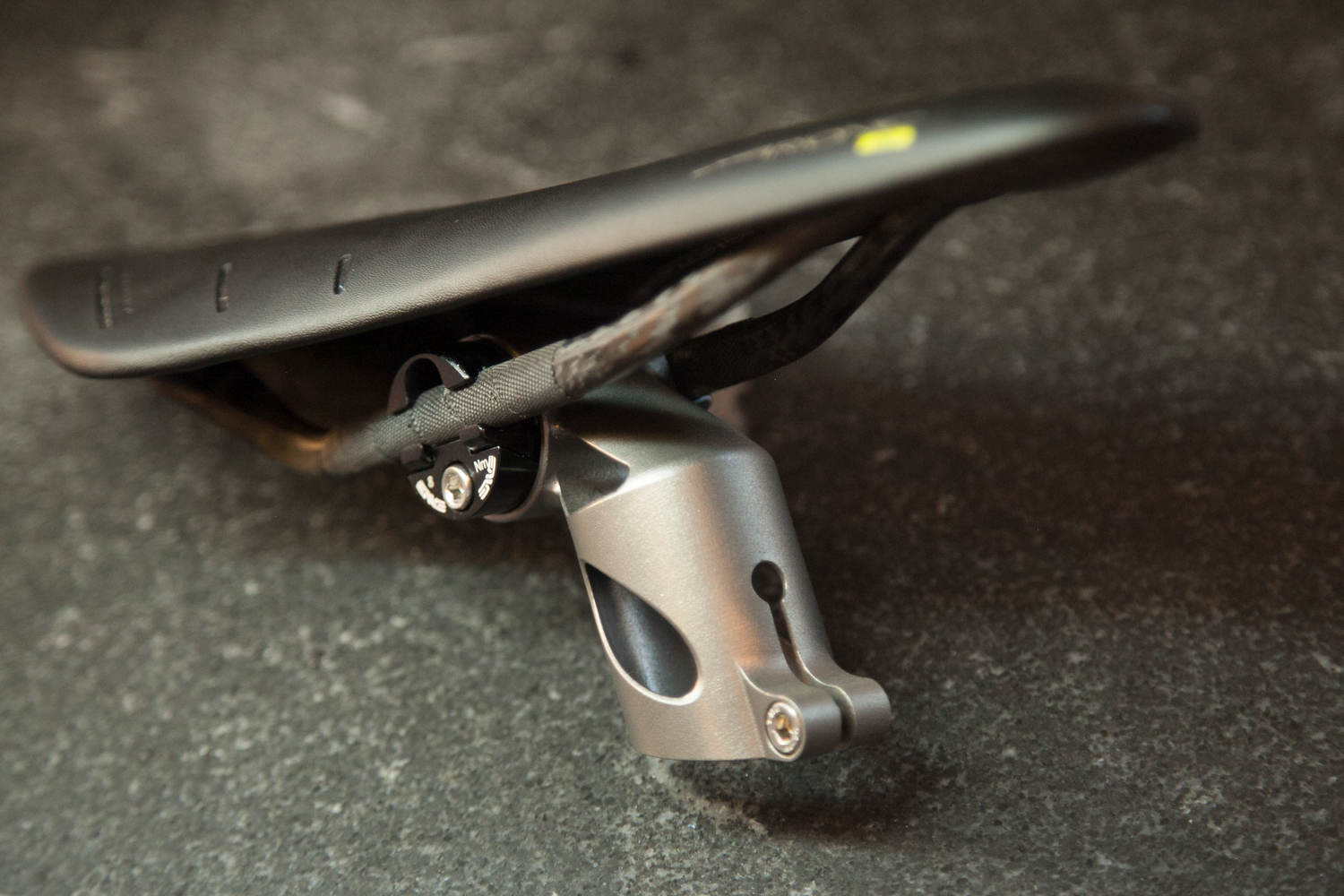
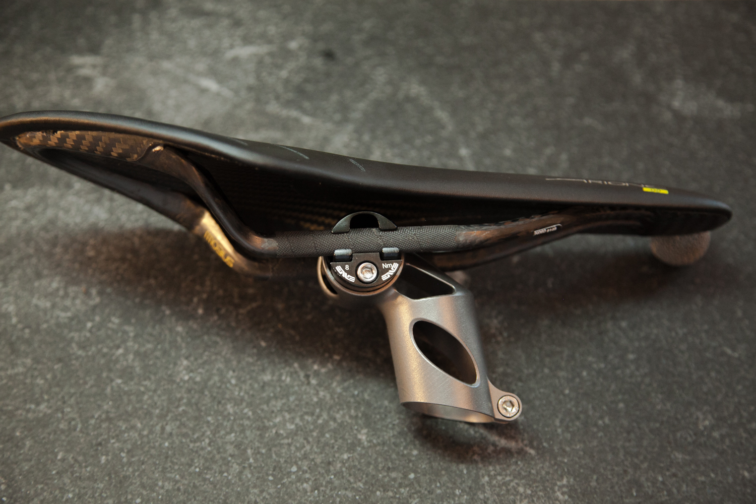
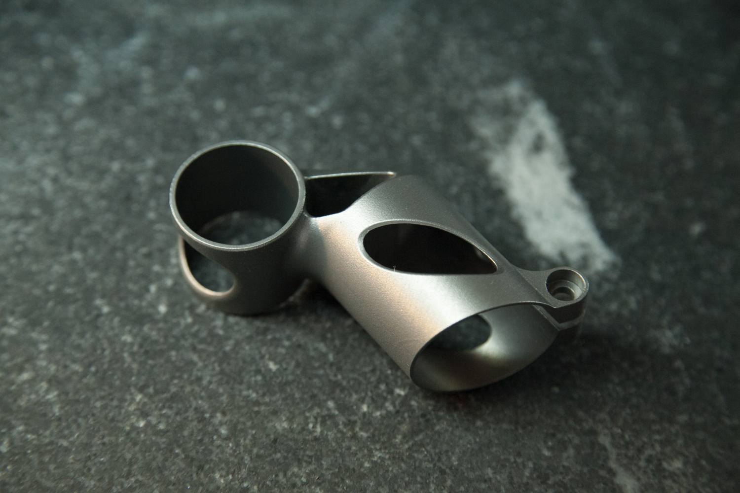
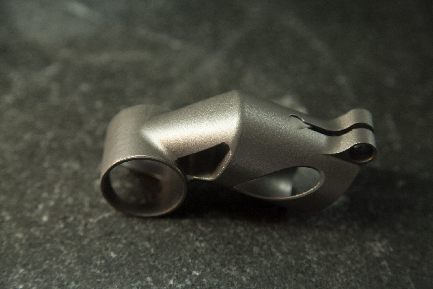
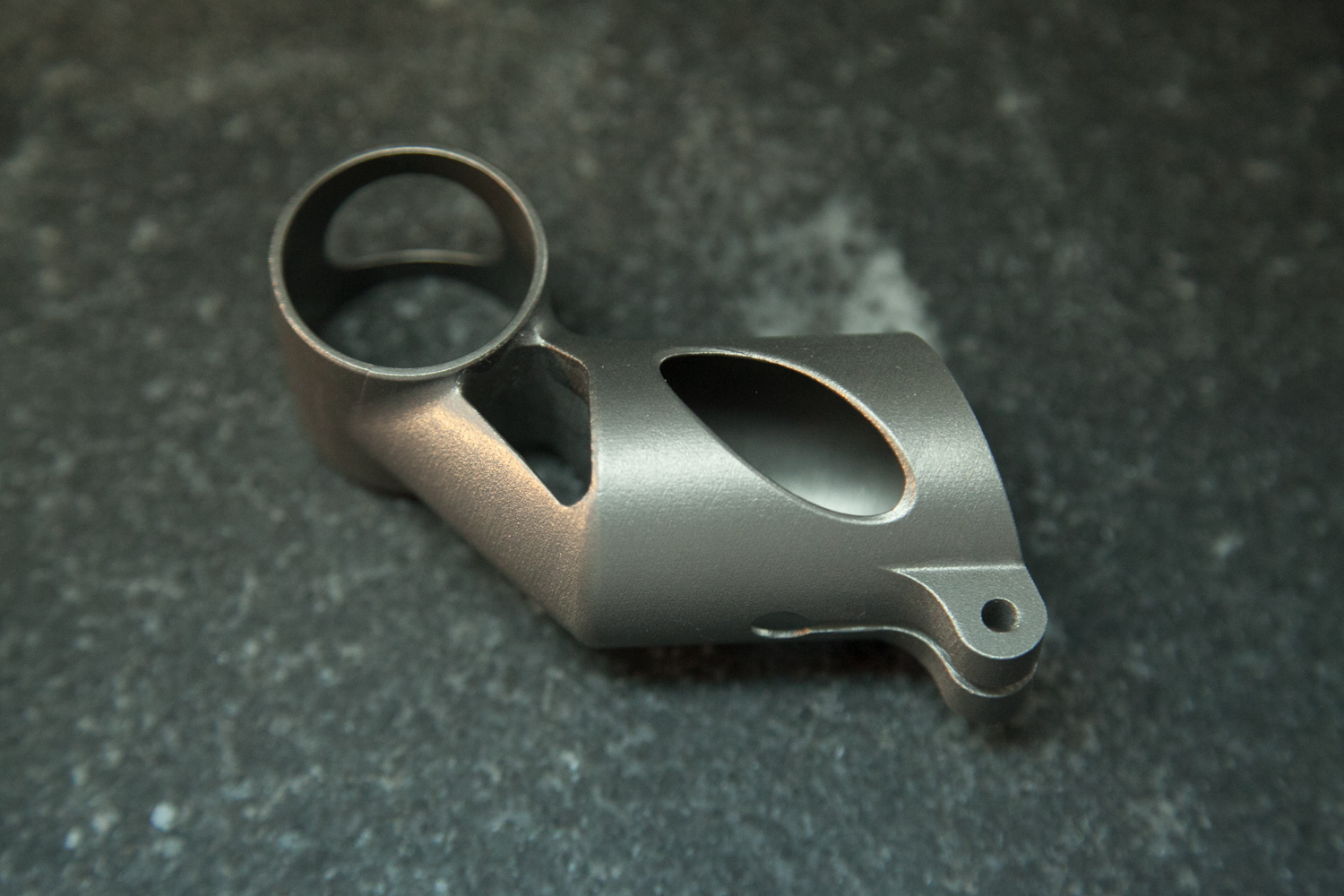
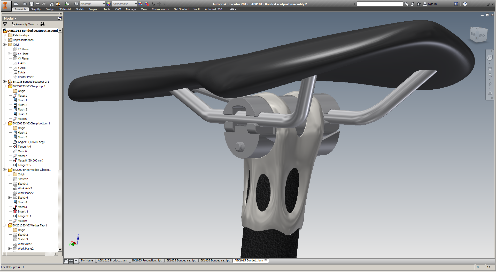
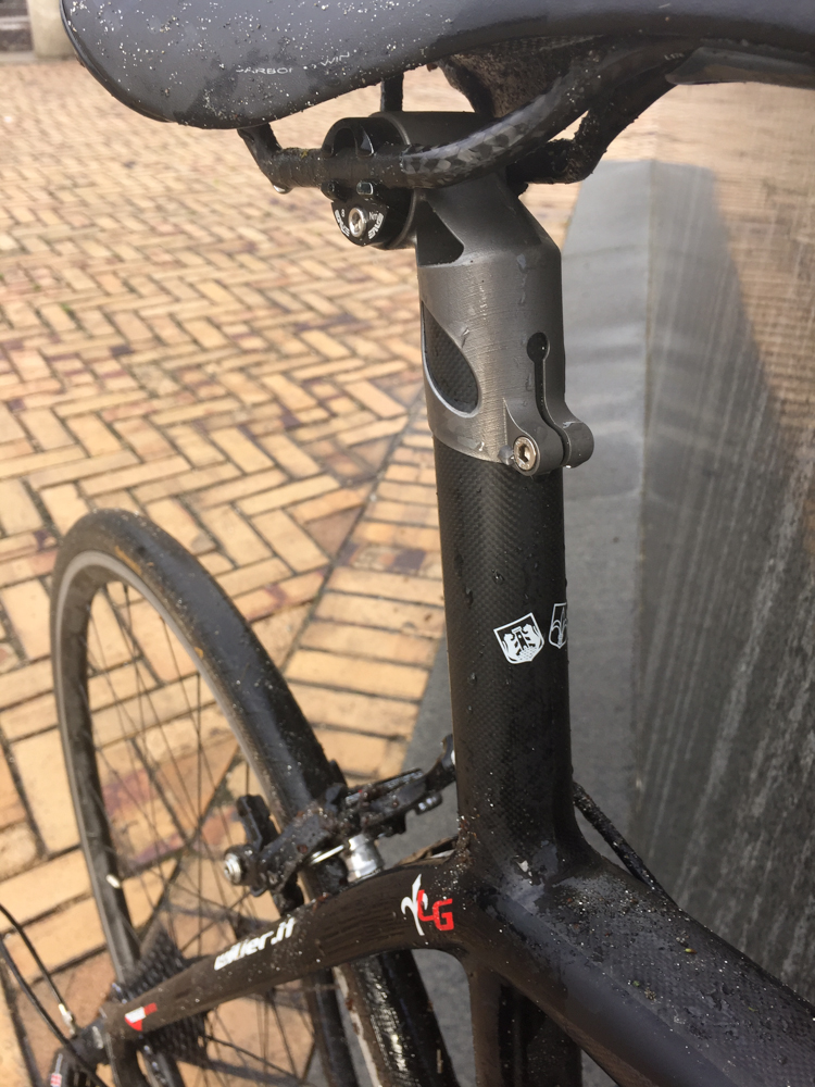
Almost a year ago, I posted a rendering of my printed bike stem on my blog here. Now:

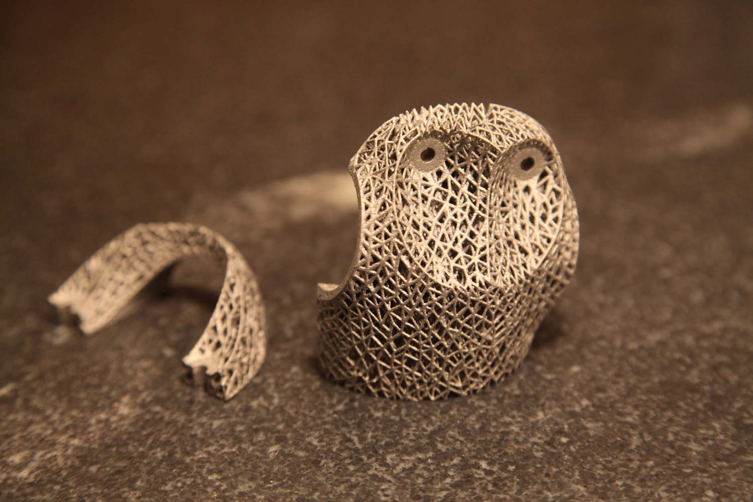
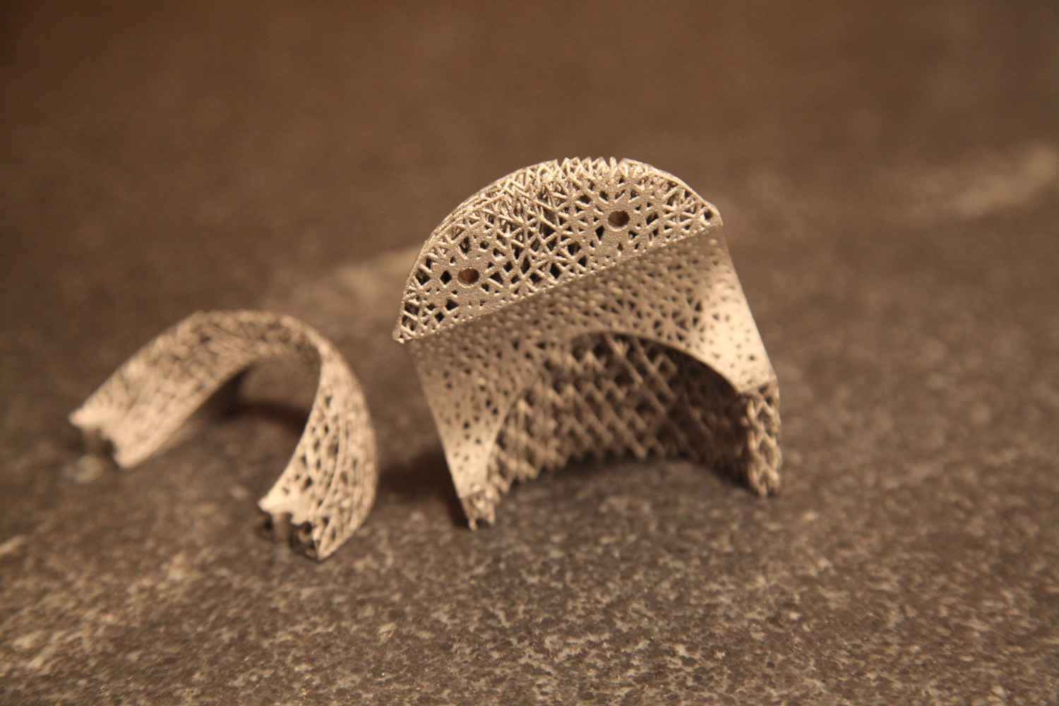
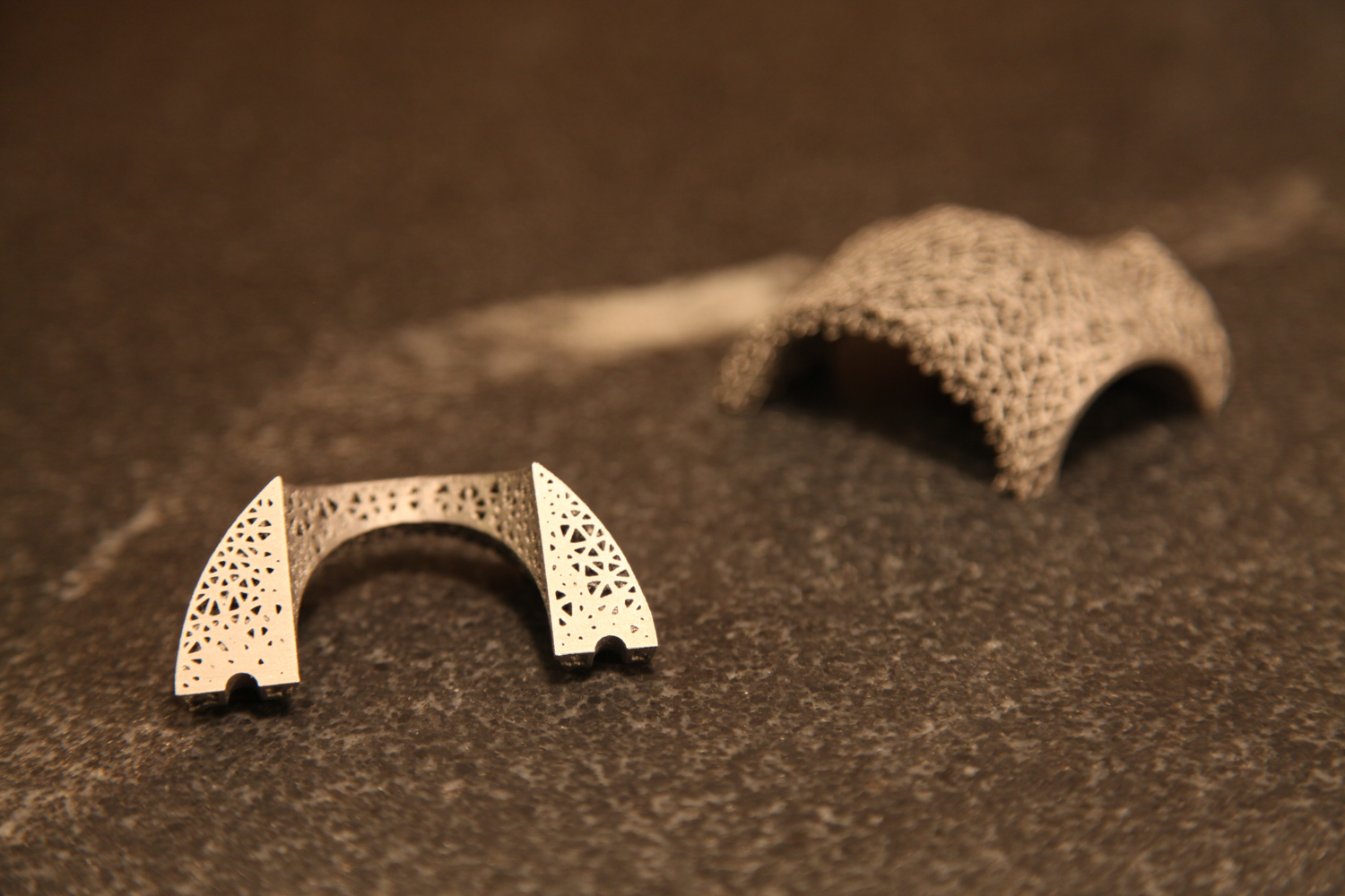
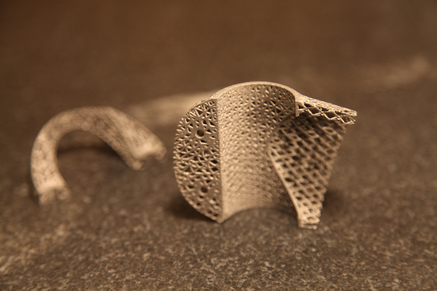
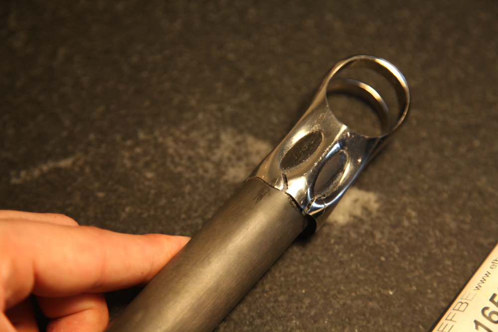
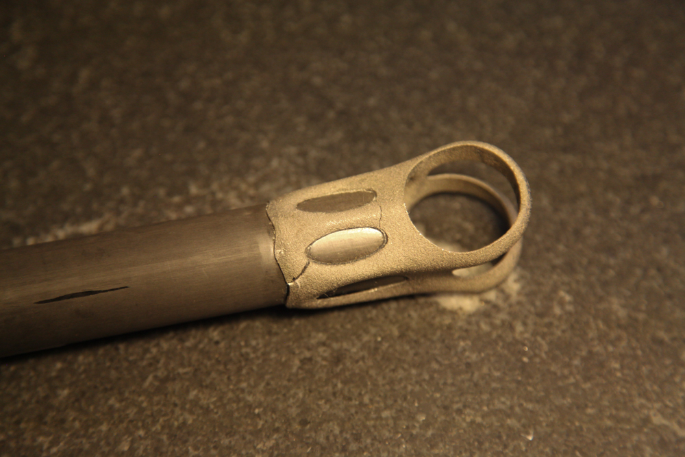
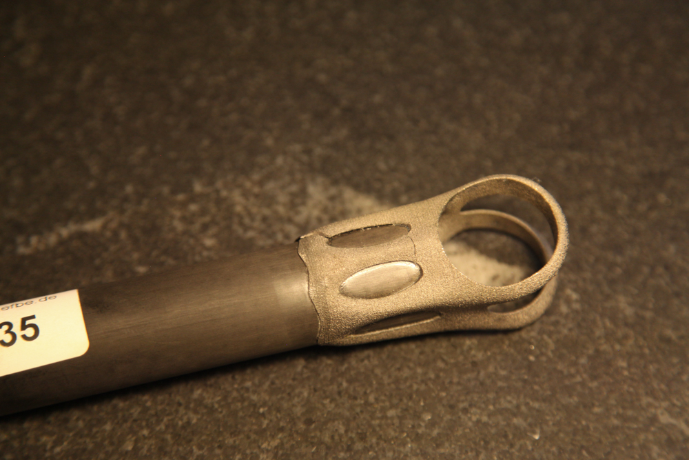
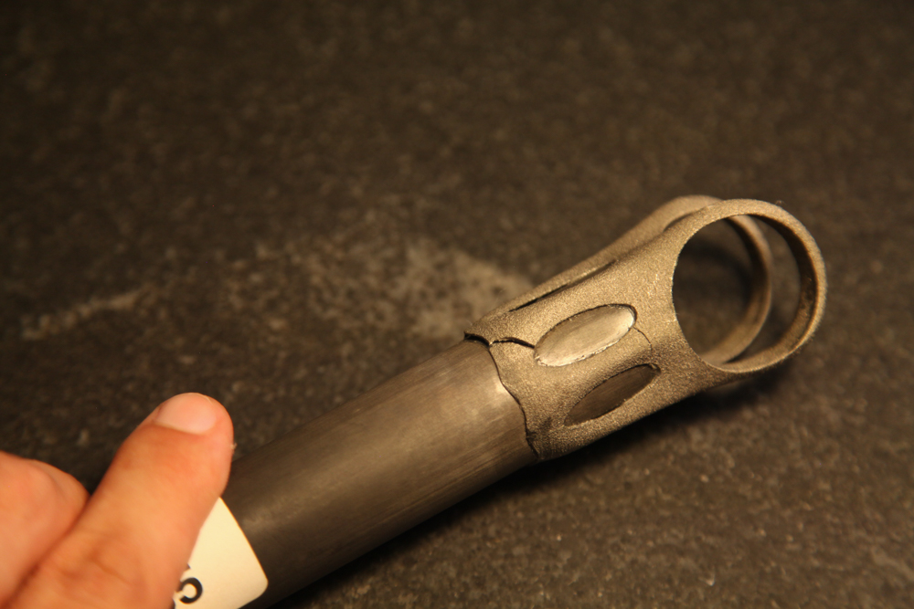
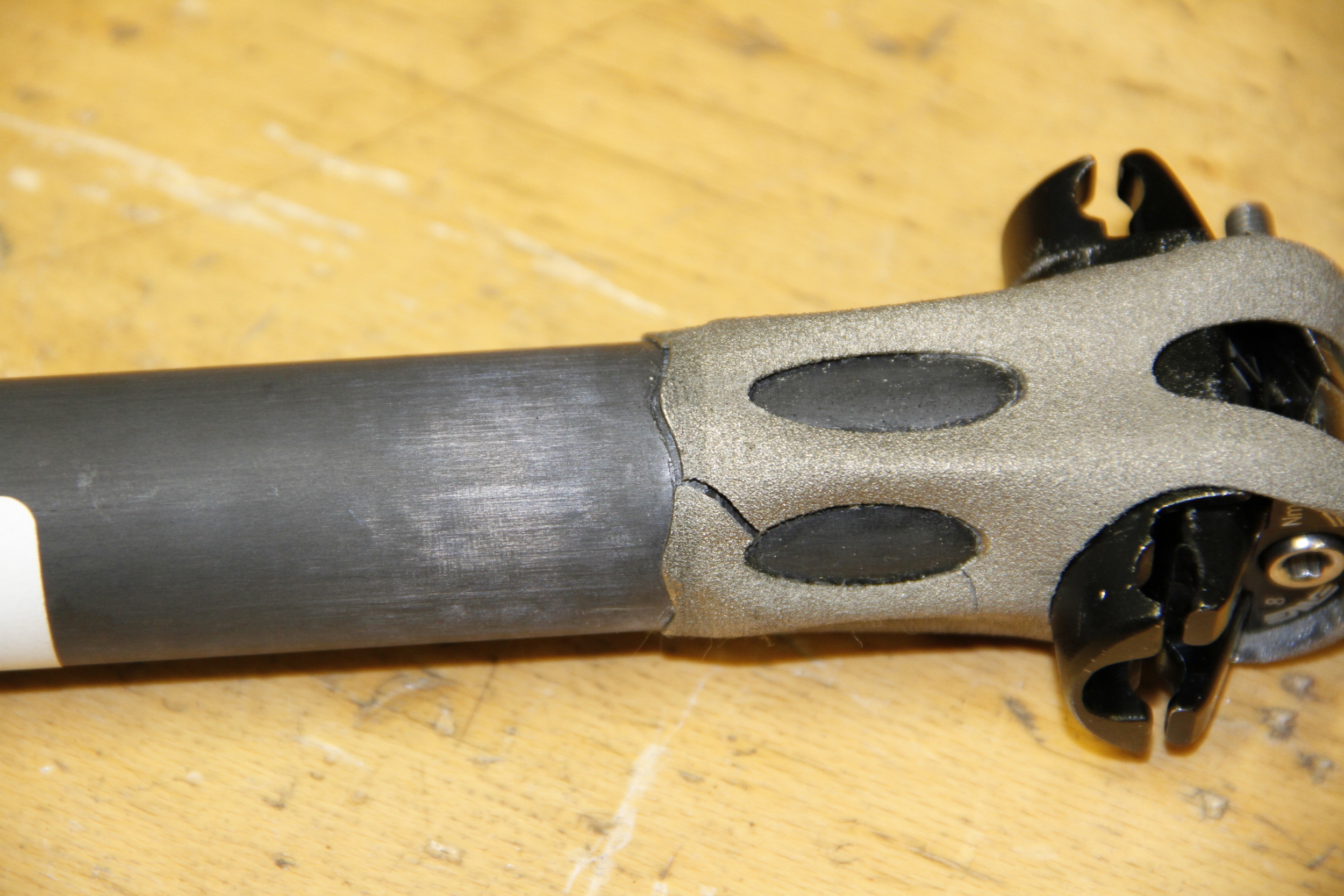
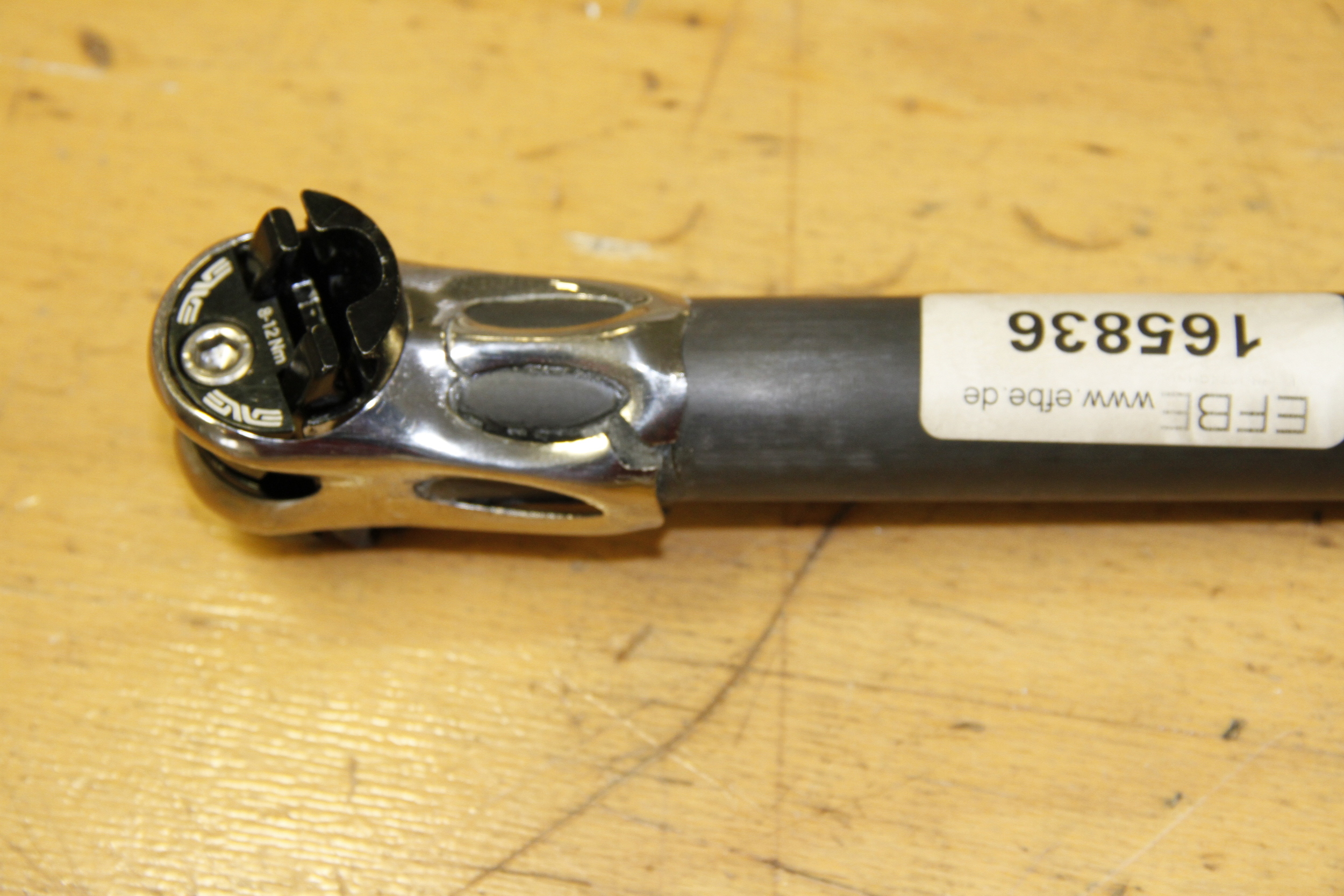
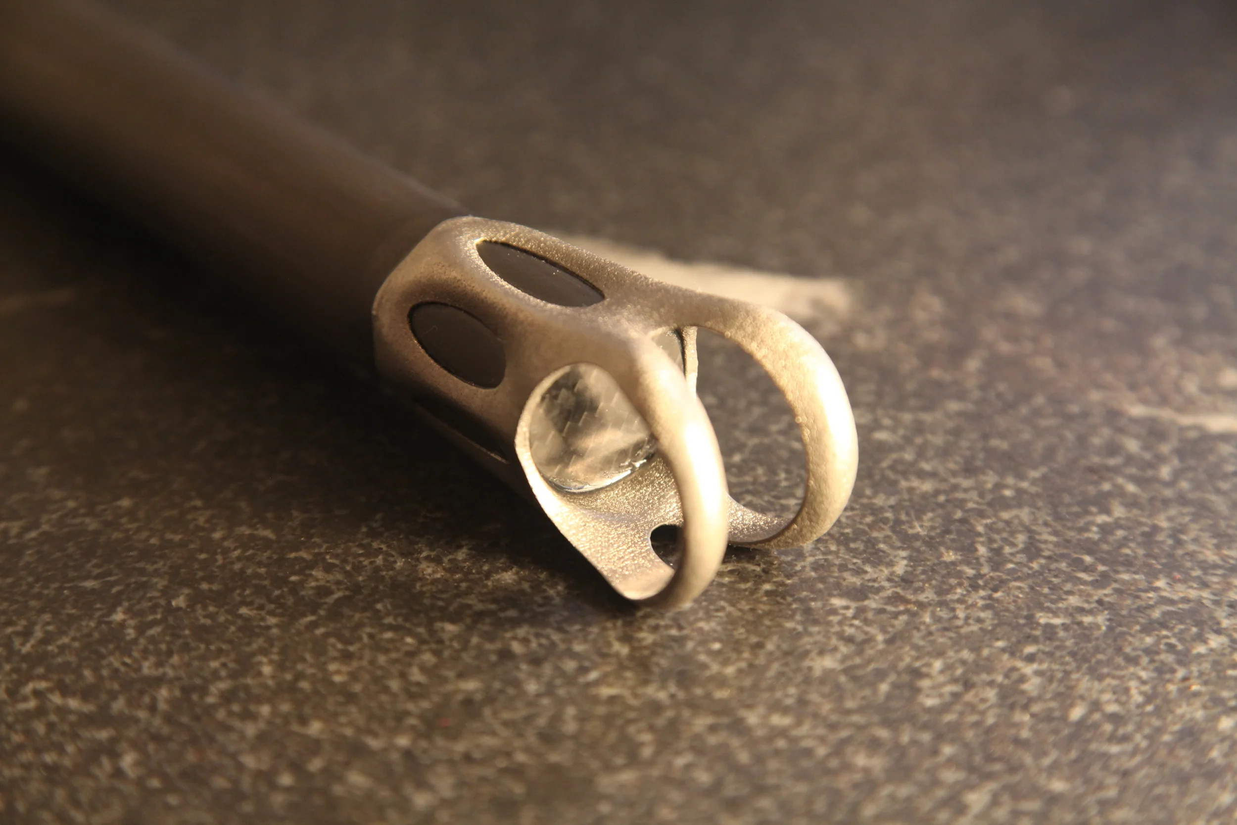
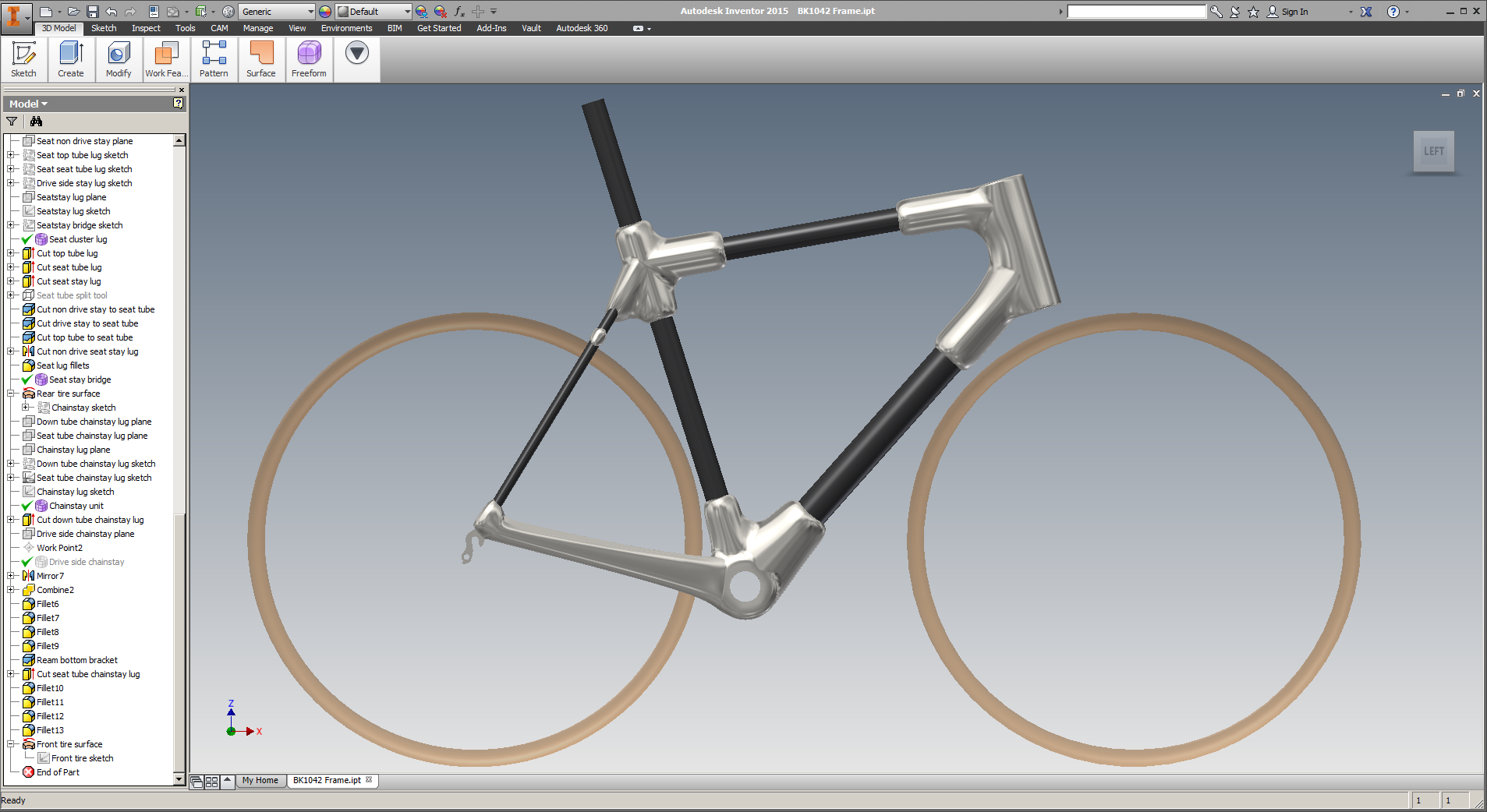
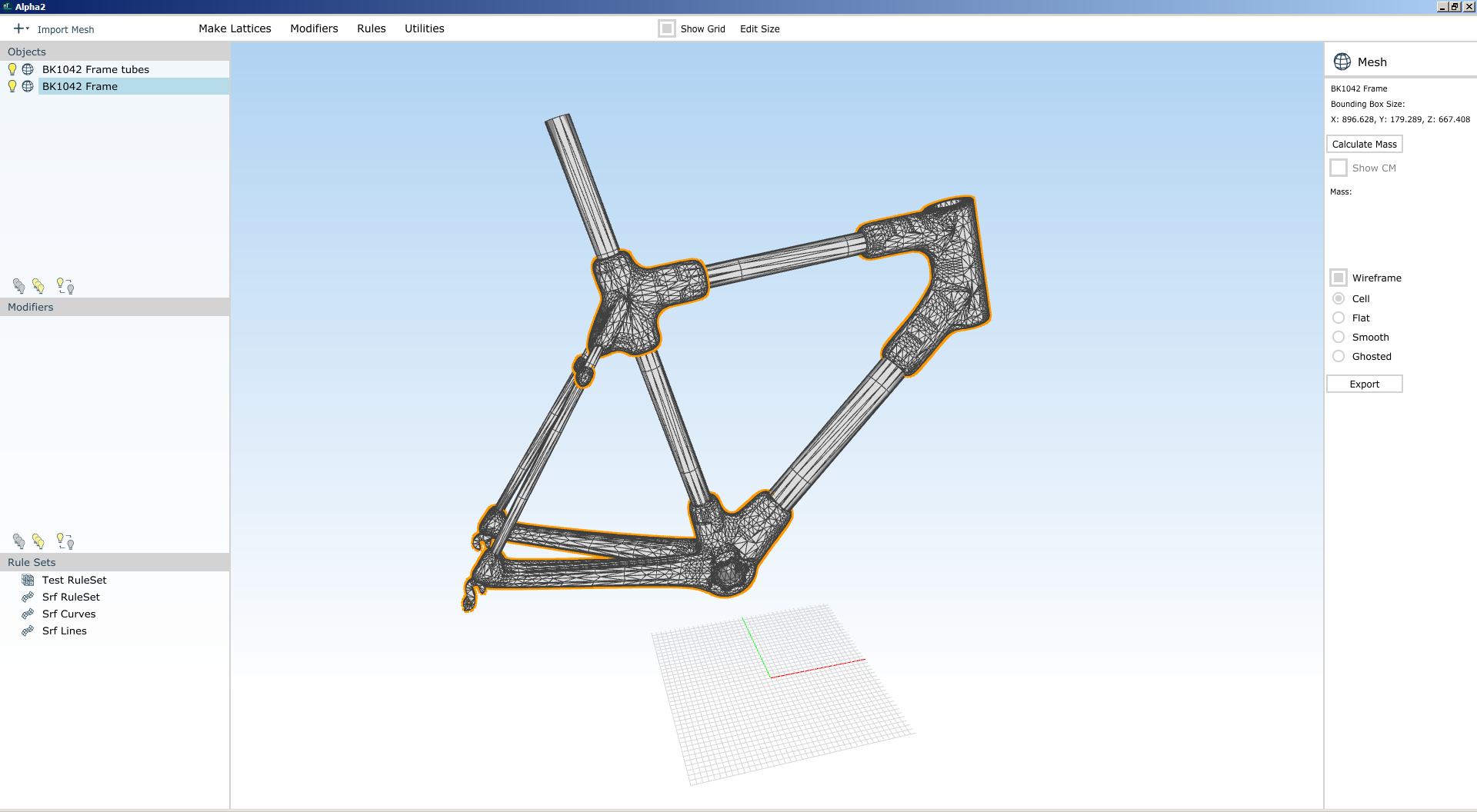
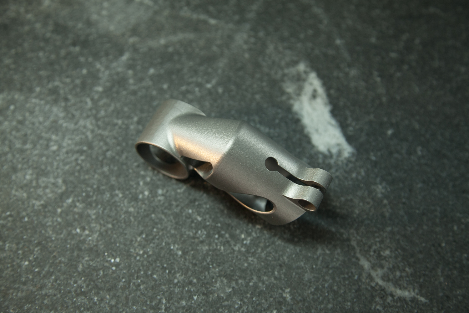
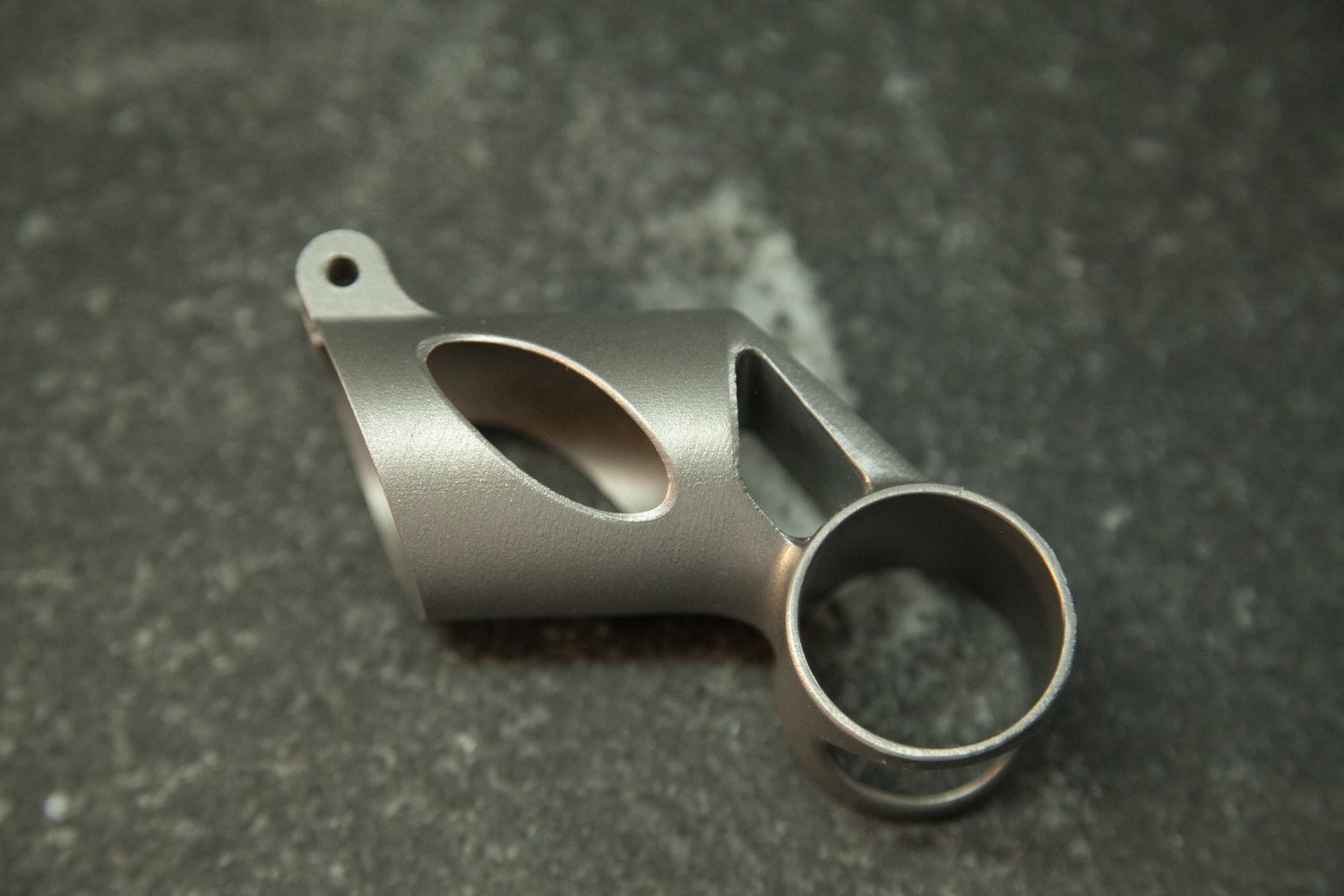
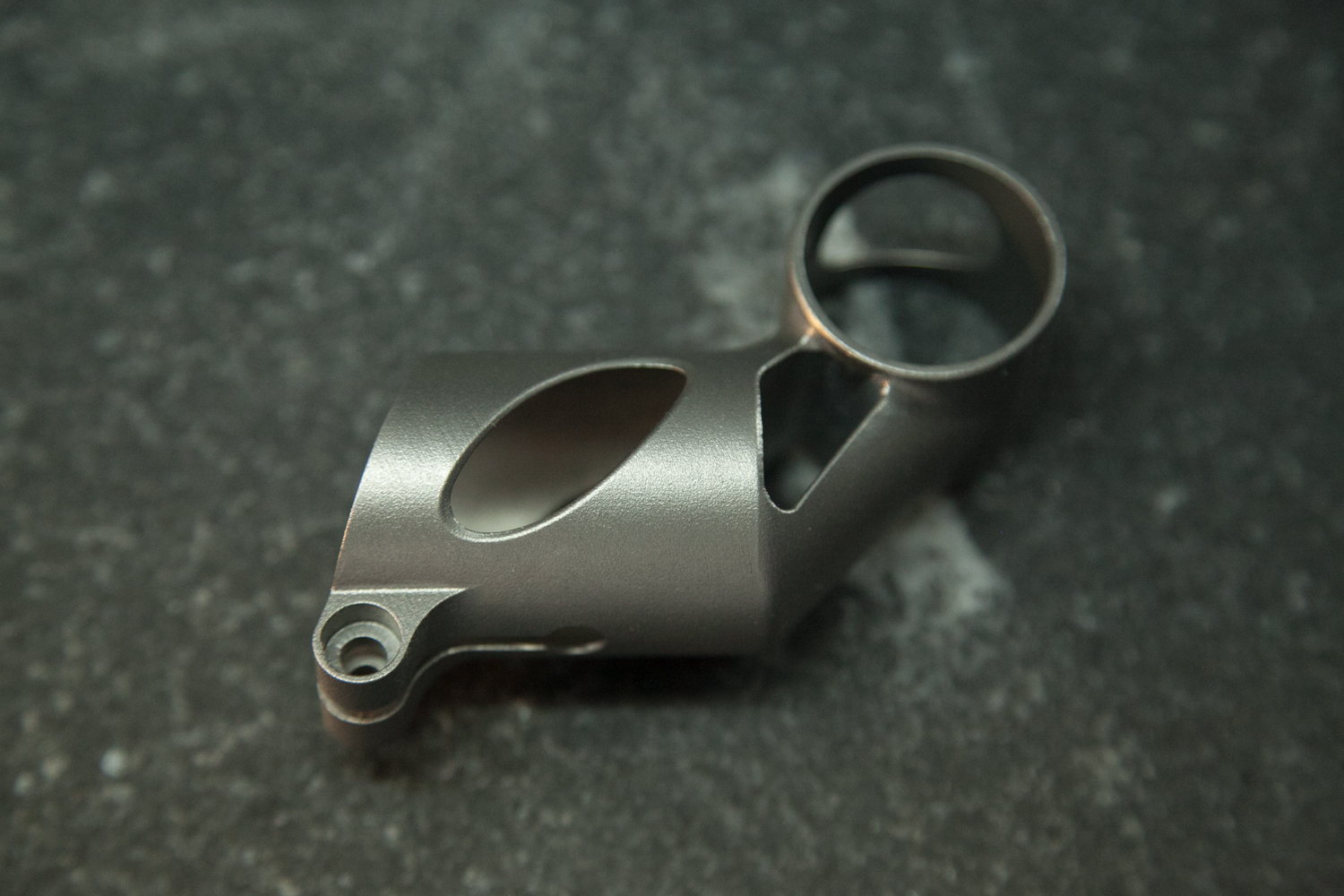
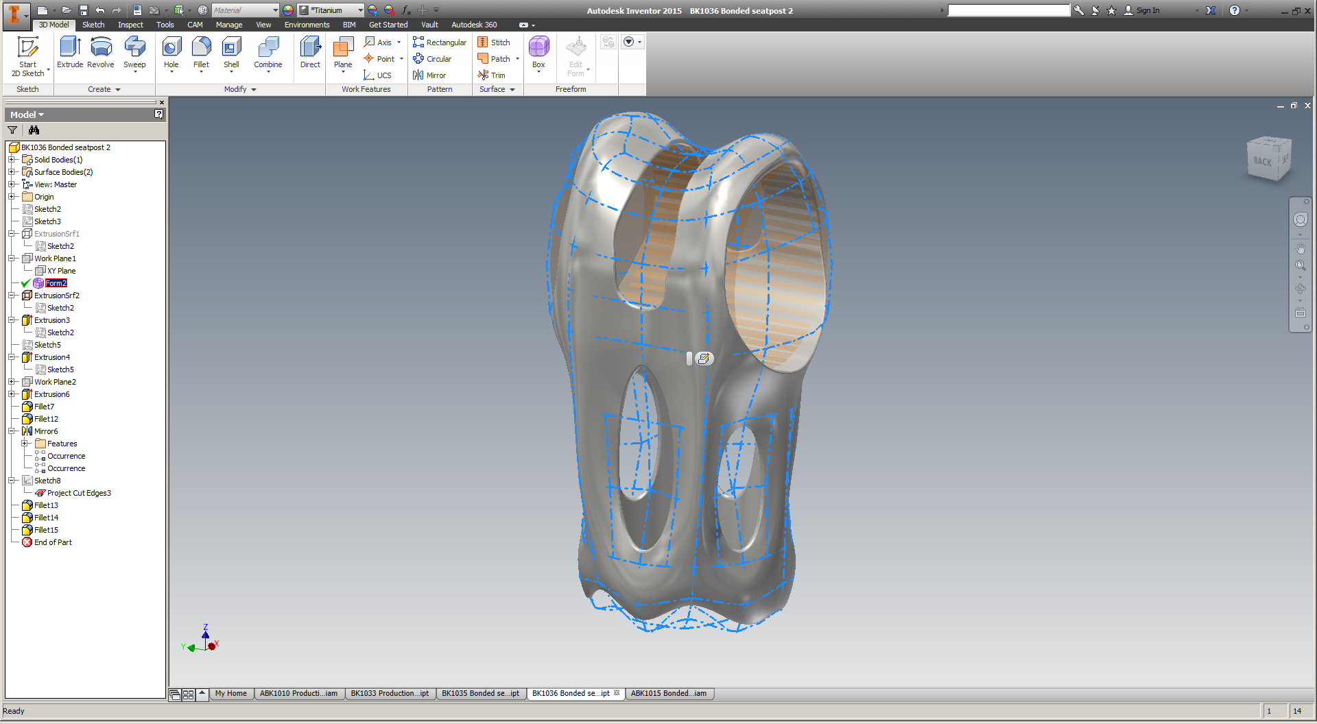
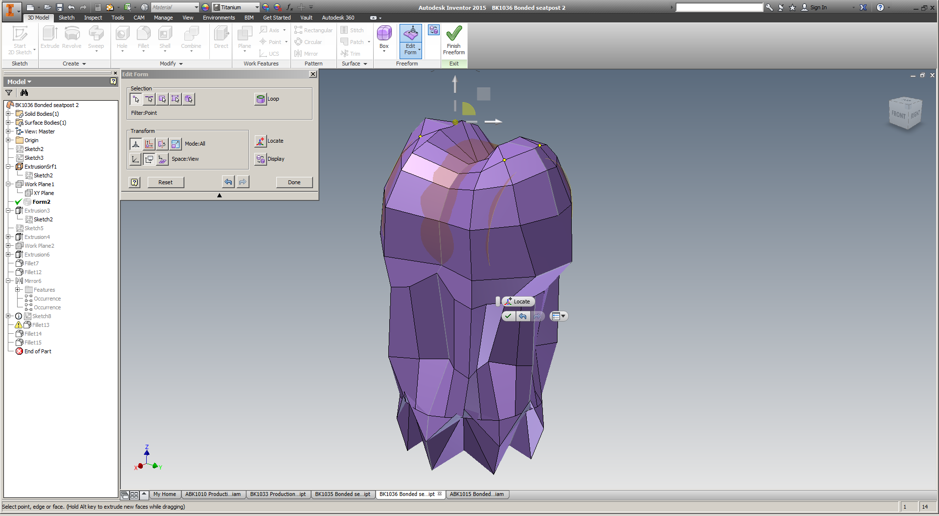
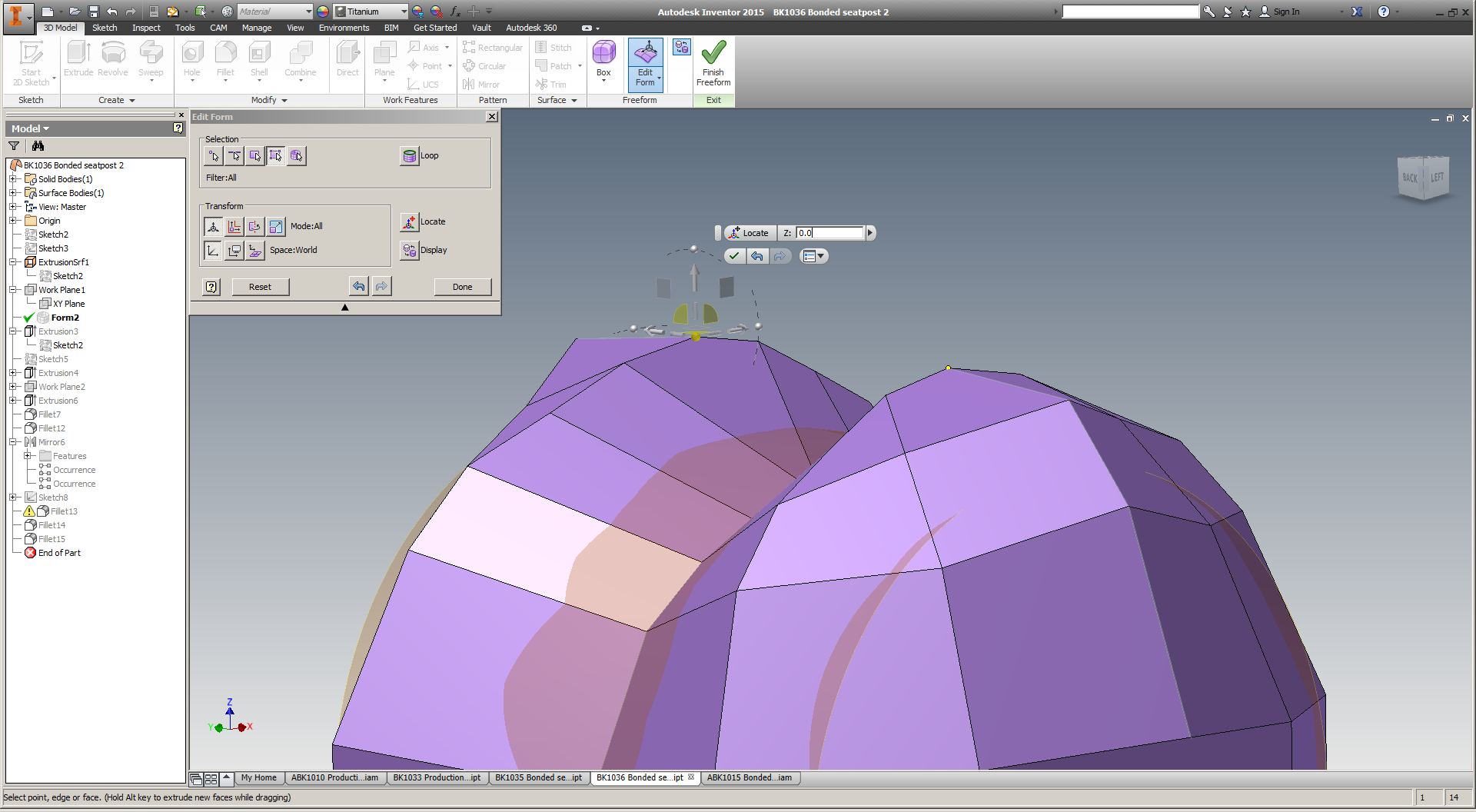
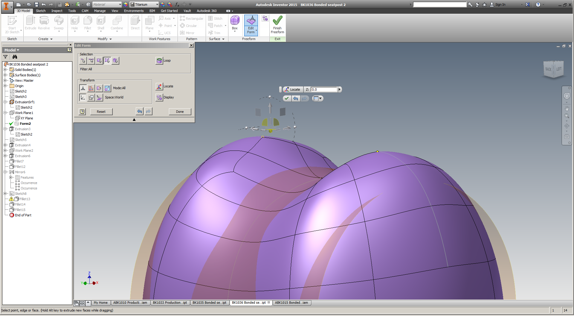
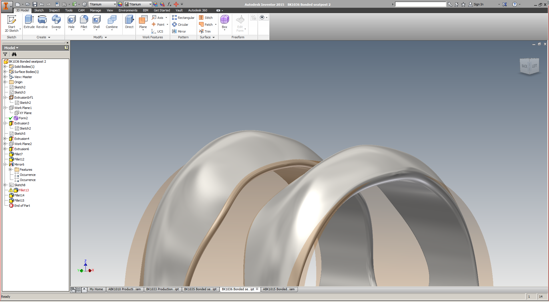
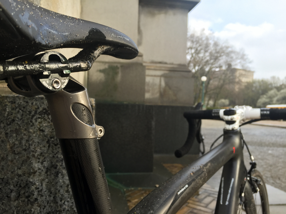
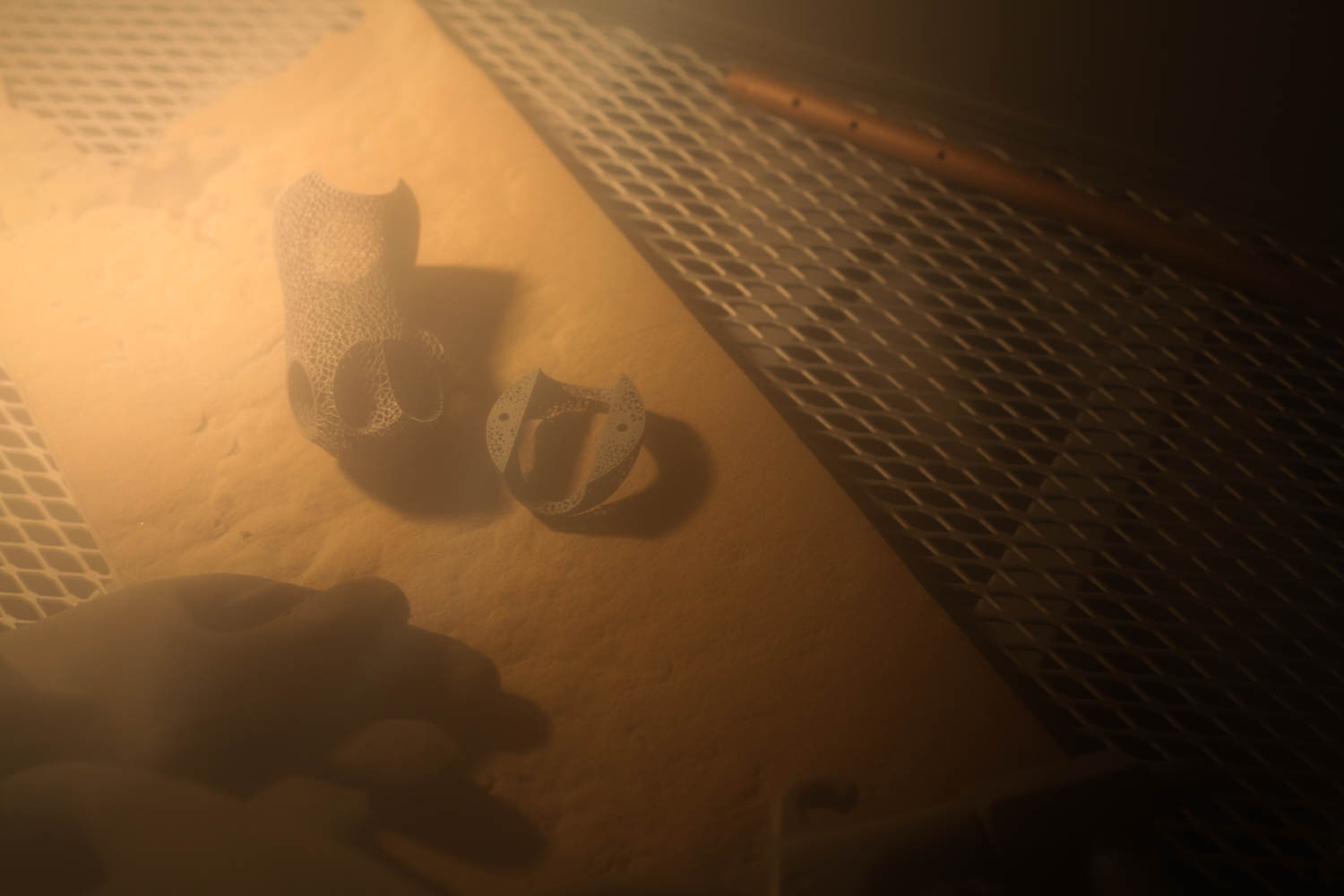
These parts were printed by my friends at Playground Global on their 3D Systems DMP320 in titanium 6/4. Like the titanium parts I've had printed (and written about extensively) in the past, these are done via laser metal powder bed fusion - the generic name that often gets referred to as "DMLS". These parts were, of course, designed in nTopology Element Pro; you can see more of my design process here

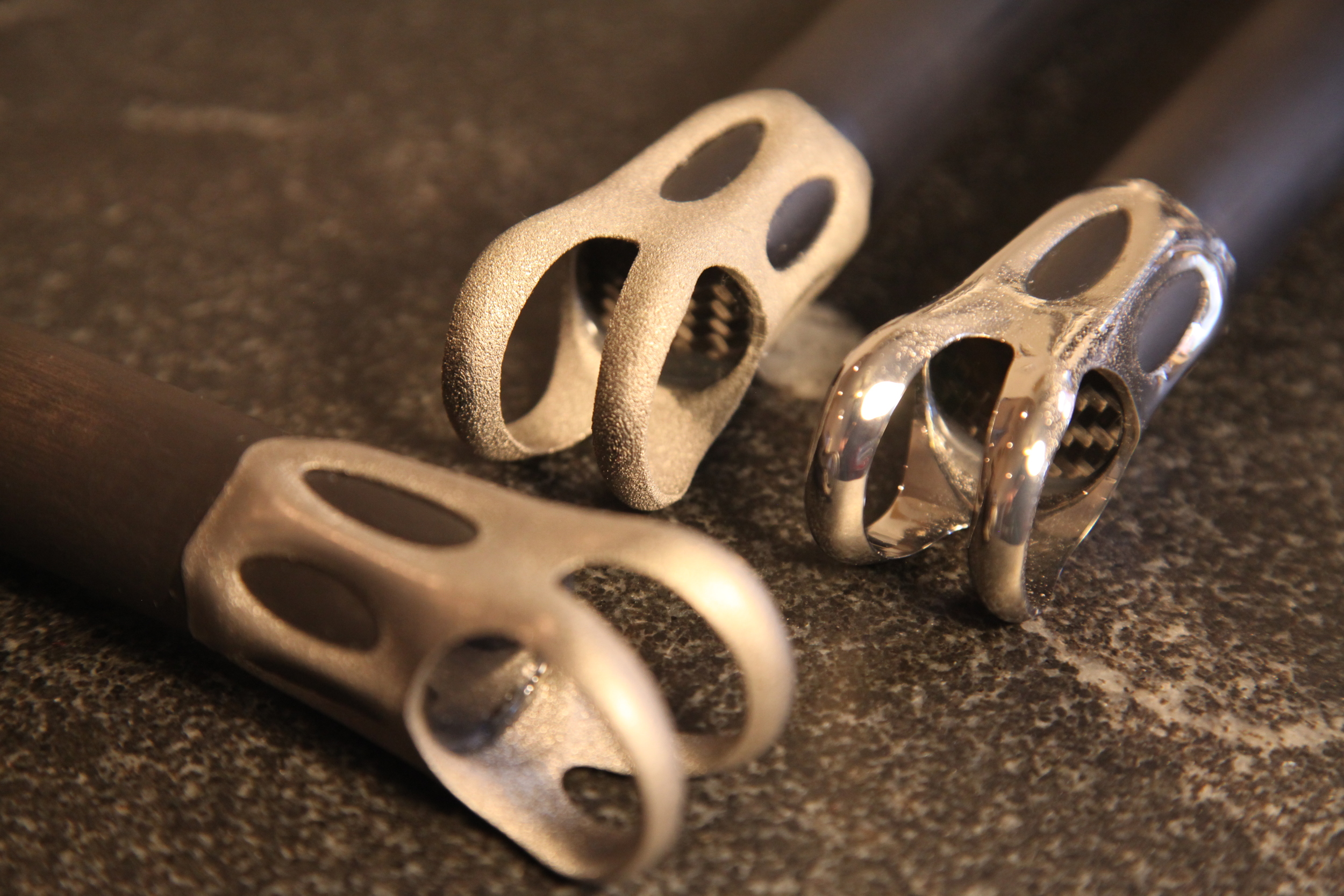
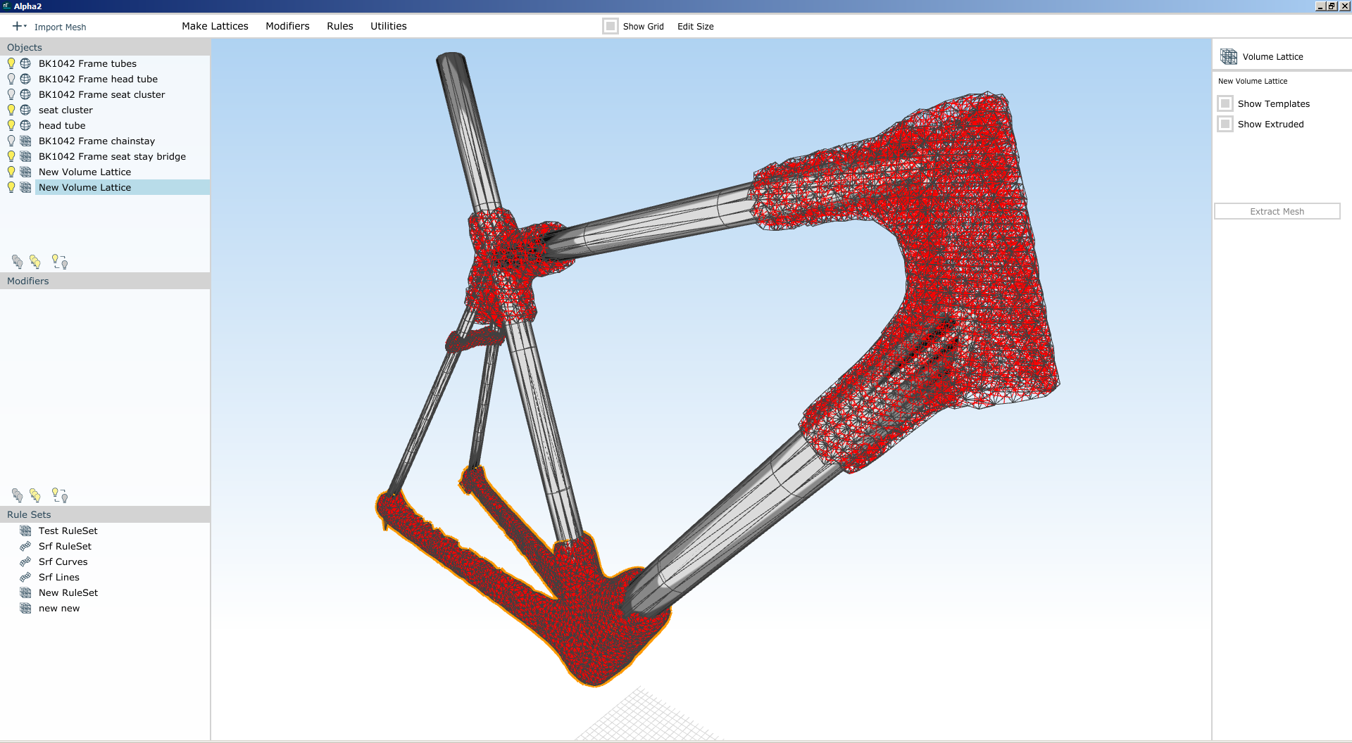
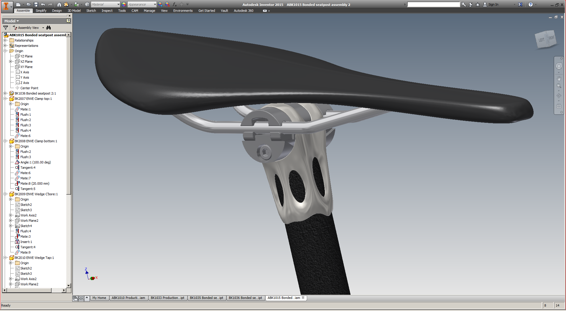
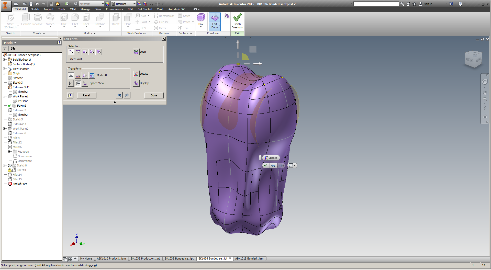
As loyal readers will know, I've put a lot of time into using Abaqus to predict these parts' mechanical properties; more on that in the near future. For the time being, the goal with this print was to test the manufacturing process - and use any lessons here to guide future design iterations. As you'd imagine, there's a *lot* that goes into printing a part that has ~45,000 beams; establishing manufacturing parameters was a good way to filter out nonviable design strategies.

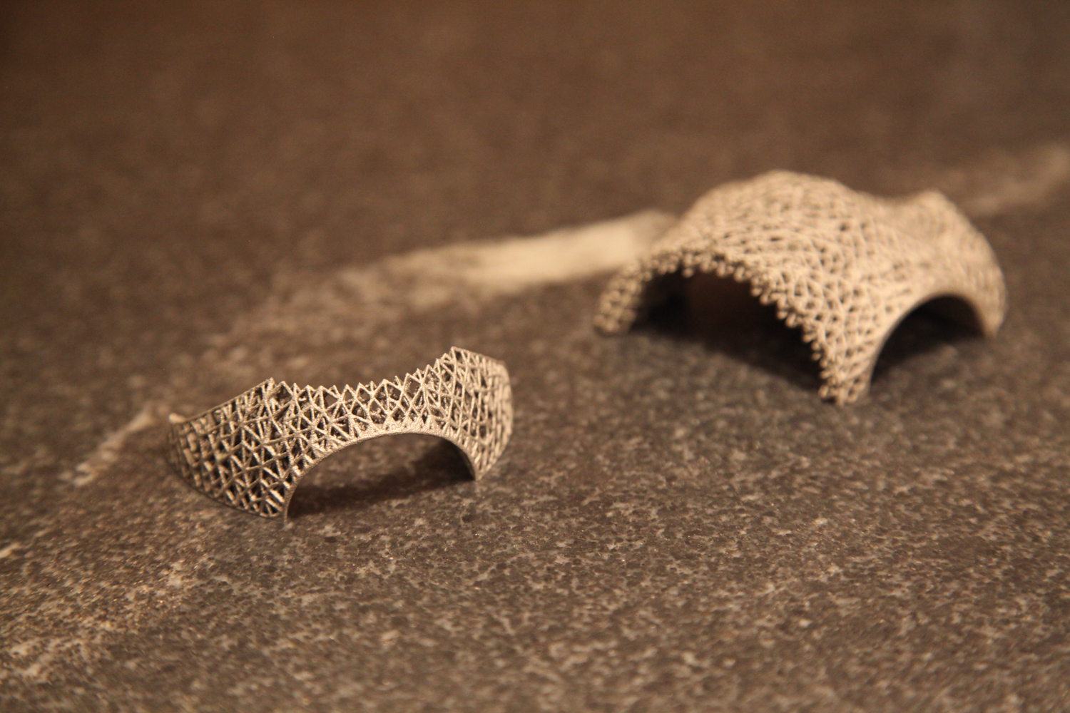
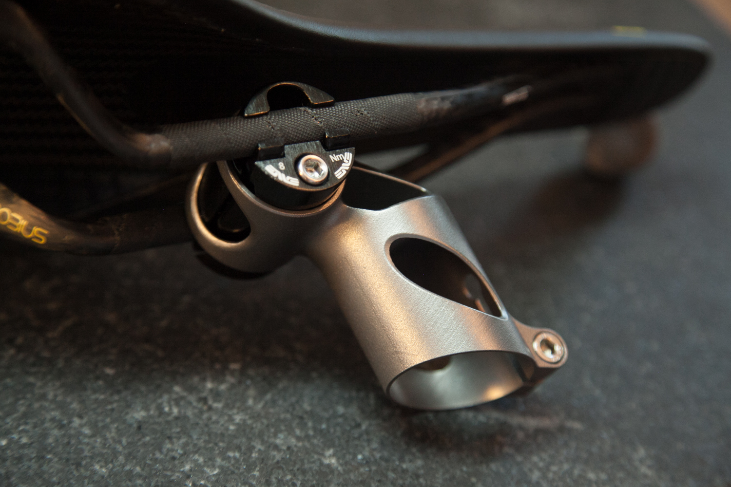
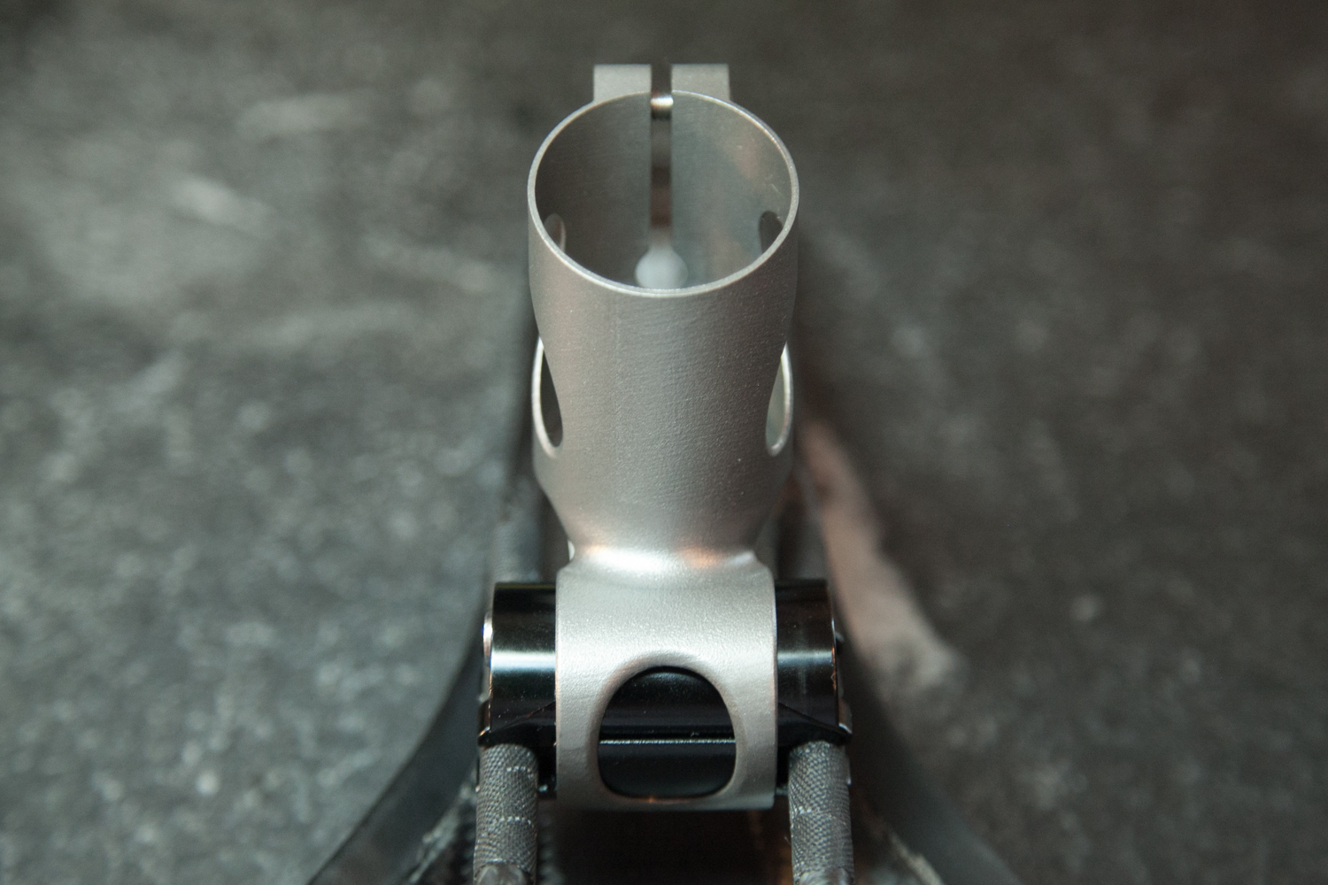
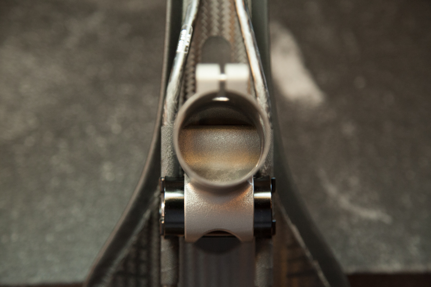
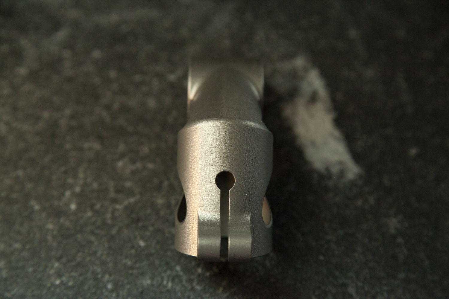
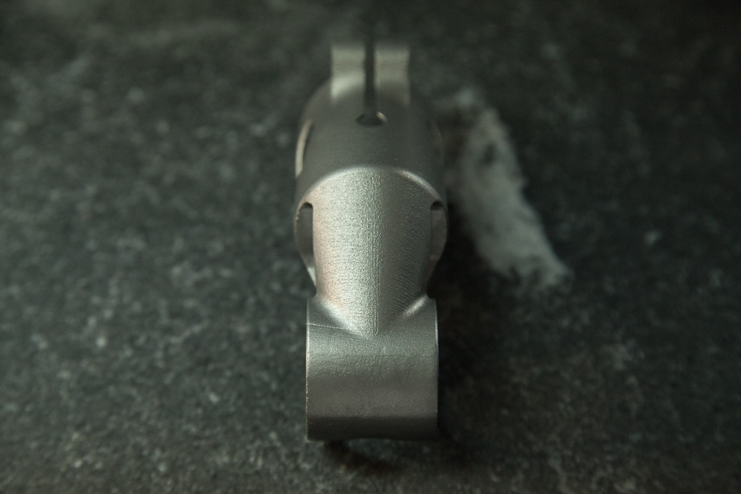
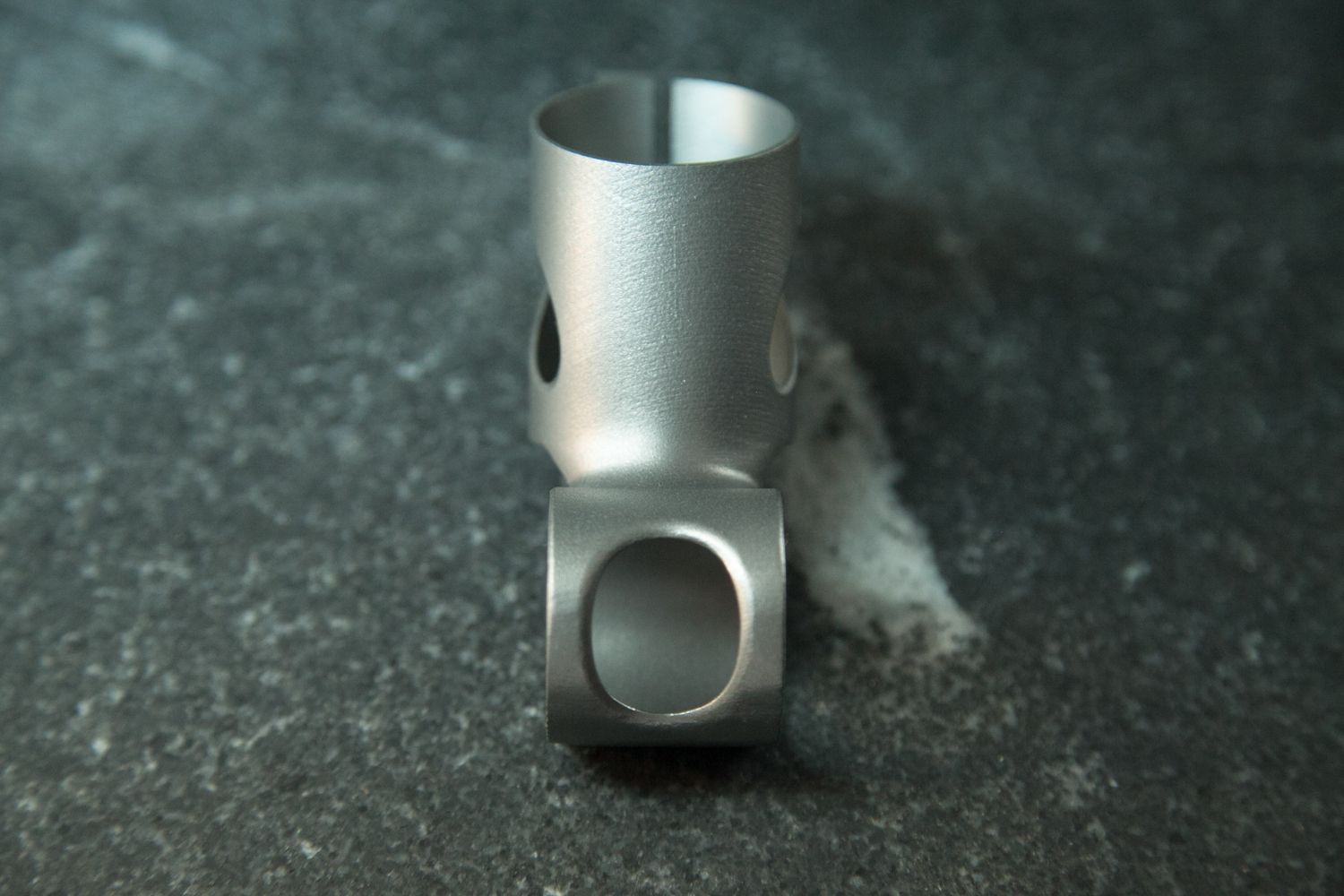
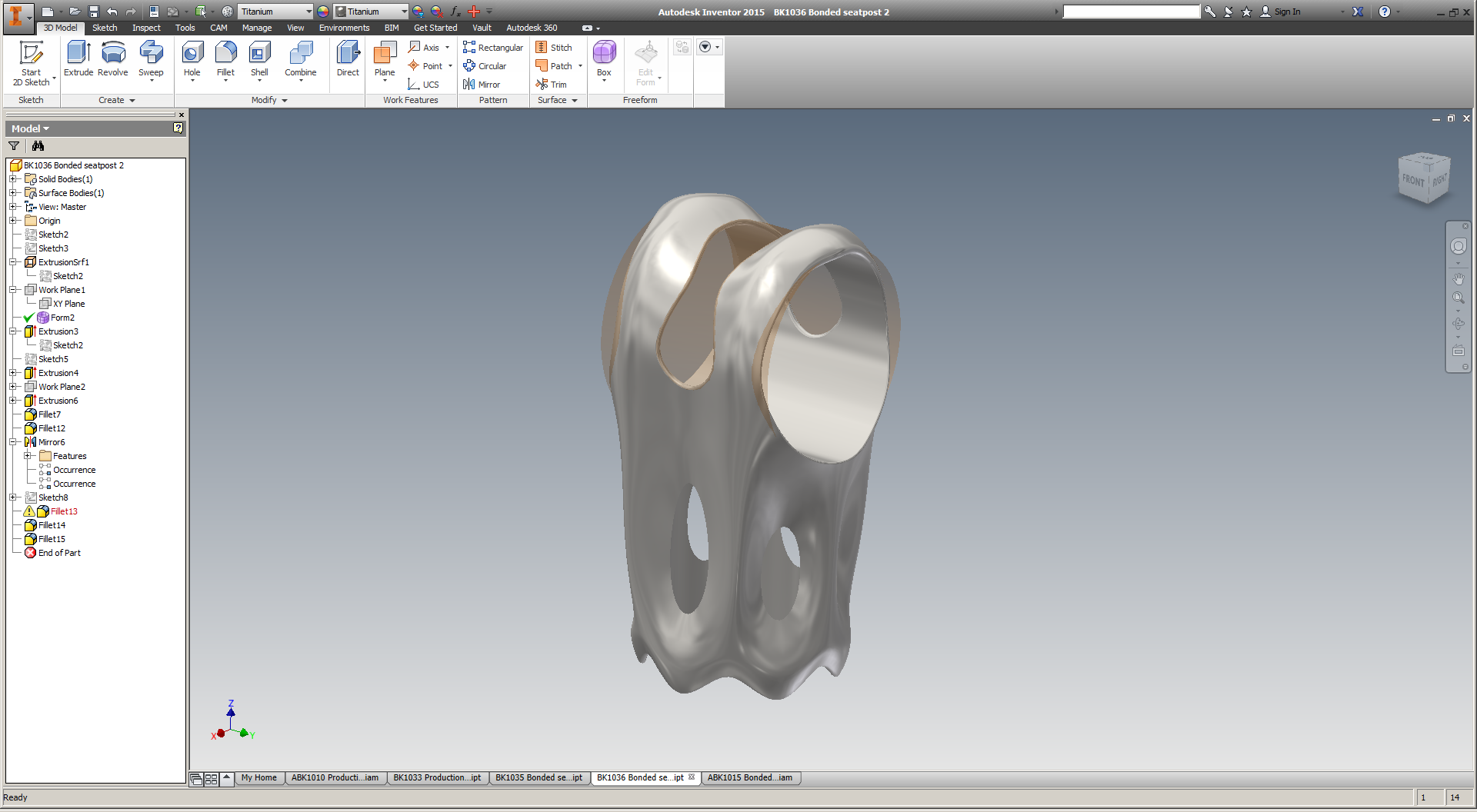
It'll take a bit more work to characterize the as-built design fully, but at first inspection it seems to have been a total success. I was careful to keep most of the beams' orientations at a high angles, thicknesses above .45 mm, and lengths below 3 mm; the result is a structure that's almost completely self supporting.

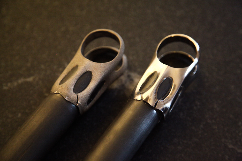
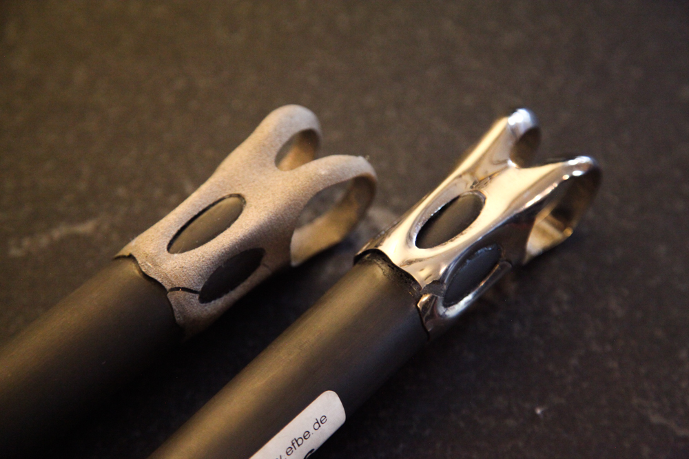
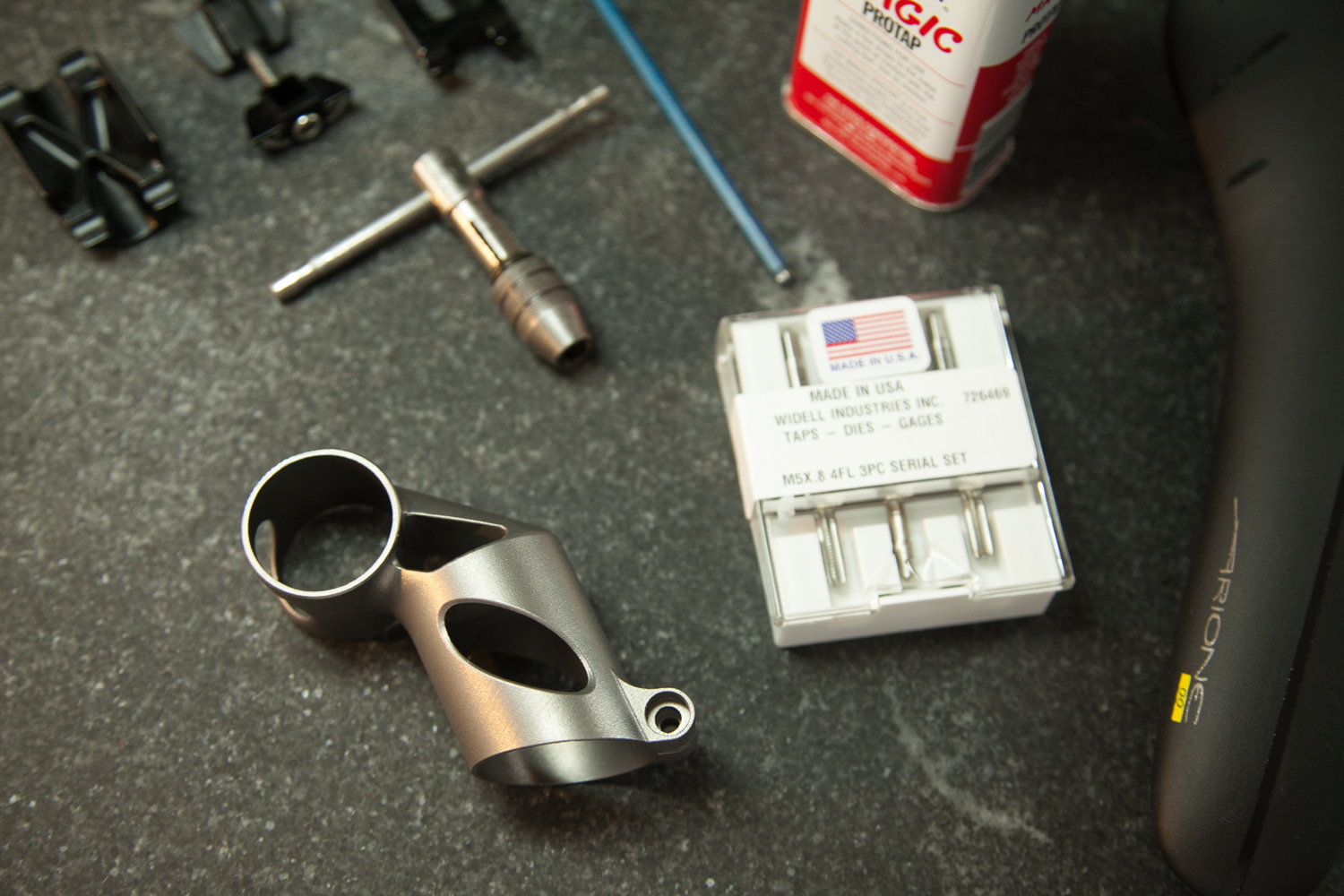
At this point, the part has been roughly cleaned up and bead blasted to remove any surface discoloration. The next step is to tap the holes, clean up the clamp surfaces, and mock the entire assembly up.

More soon :)

See also: DMLS lattice sample prints, where I describe the part's design a bit more.

DMLS lattice sample prints

Added on by Spencer Wright.

I'm *very* excited about these parts from C&A:

These parts were printed in titanium 6/4 by C&A Tool in Churubusco, Indiana; they were designed in nTopology Element. 

This is a pure lattice structure - the entire geometry is designed as beams and nodes, with no explicitly defined solid regions. The beam lengths are on the order of 2-3 mm; their thicknesses range between .45 mm and 1.1 mm. In some areas (for instance, the bolt holes) this results in a fully solid part, but the transition from lattice to solid is continuous rather than discrete. The result is a structure that's solid where it needs to be and sparse elsewhere, with no stress risers where solid and lattice meet.

The parts are, of course, sample regions of the bike stem that I've been working on for some time now. The intent of the samples was to prove the printability of the structure and identify any potential difficulties. The results were overwhelmingly positive: With the exception of a few small flaws, the parts printed very well, and I believe the problematic areas can be addressed in the design pretty easily.

Given the good quality of the sample prints, I'm planning on printing a full version of the part soon. I'm also experimenting with a few other design variations (intended for a variety of different metal AM machines), and am running them through a beam sizing optimization process with Abaqus and Tosca in order to reduce mass and decrease strain energy. More on these soon :)


Thanks to Rich Stephenson for his ongoing help on this project - and for continuing to educate me on the metal AM industry.

Seatpost testing post-mortem

Added on by Spencer Wright.

This week I got my seatposts back from testing at EFBE. As you'll recall, these failed ISO 4210-09:2014, 4.5.2. 

The part's nomenclature

Both seatposts failed in essentially the same way: The shoulder straps rotated backwards, breaking the skirt in two locations and cracking both of the side legs as well. The front of the skirt separated completely from the carbon fiber post at the bottom, and the top/front of the seatpost cylinder appears to have slipped upwards (sheared) as well.

The "BLING" part (see this post for details on the difference between the two samples) failed slightly before the as-printed version, at 70,770 cycles. It's a bit hard to tell in the photos, but there are definitely some areas where I didn't have enough glue to form a complete bond. Part of this is operator error (i.e. my fault for not assembling the seatpost well), and part of it is engineer error (i.e. my fault for not designing the seatpost so that it could be assembled by any grease monkey). 

The as-printed part failed a bit later, at 80,904 cycles. Again, close inspection shows that the glueline had many defects.

I take a few lessons from this:

First, it's clear that my assembly design needs to be improved. It's possible that the part still would have failed with a better glue joint, but at this point in my process it's important that I'm able to isolate possible issues - and variations in bond quality makes that *really* hard. I suspect the best approach here is to make the glue cavity captive, such that during assembly the uncured adhesive is forced to fill the full volume between the seatpost head and the carbon fiber post.

This likely means eliminating the windows from the seatpost cylinder. It also means either creating a double lap shear joint (like Robot Bike uses) or making the joint blind on both sides (by capping the end of the carbon post, which I did on this assembly, *and* closing the top of the seatpost cylinder, which I didn't do). 

Second, I should probably be HIPing these parts - at least until I've isolated everything else and determined whether, and how, HIP affects performance.

Third, I'd like to dial in the inner diameters of both the seatpost cylinder and the saddle clamp cylinder. The latter can probably tolerate a bit of play, but the former directly affects the glueline and should probably be controlled more tightly.

On the upside: The failure mode on these parts wouldn't have hurt the rider, whereas failure in the shoulder straps could have been dangerous. In addition, I've got a chance to try this again - with the parts that REM treated for me recently. I won't be able to change the original design at all, but I can at least try to see whether a change in technique can improve the glue joint.

Regardless, it's good to get tested parts back. More soon!


Note: Thanks to Addaero Manufacturing for printing these parts, and to MicroTek Finishing for finishing them!

Seatposts, tested

Added on by Spencer Wright.

Today I got word from EFBE that two of my EBM seatpost had been tested - and failed.

These are the as-printed and the "bling" samples (see this blog post for details); they failed after 80,904 and 70,770 fatigue cycles (at 1230N), respectively. As a result of their failure, I decided to not test the third "fatigue resist" part.

I'll write up a longer description of the results soon, but two thoughts here:

  • These parts were *not* HIP treated - which might possibly have helped their fatigue resistance.
  • It appears that some delamination occurred between the printed parts and the carbon fiber post, which makes me question whether the glueline itself was faulty. If so, it's possible that by improving my glue joint I could have relieved some stress from the printed part. Regardless, I will note that the glueup process was kind of a pain in the ass - and I'd like to redesign that anyway.

As it happens, I have three more of these parts on my desk now. They *were* HIP treated, and I intend to glue one of them up and send it for testing. It won't be a perfect 1:1 test (these parts were treated by REM Surface Engineering, through a different process than MicroTek uses), but the results will be interesting at the least :)

Onwards!

Seatposts assembled

Added on by Spencer Wright.

Before I send these three seatposts out for testing, a quick update:

The seatpost heads (which I wrote a detailed post on a few months ago) are now glued to carbon fiber posts. I also added a thin carbon fiber disc to the top of each of the posts, so that water can't get into the bike's seat tube. The whole thing was assembled using 3M DP420 epoxy.

These are headed back to EFBE this week, where they'll go through the same ISO test as my seatmast topper was subjected to. More details soon!

Fresh AM titanium/carbon fiber bike frame designs

Added on by Spencer Wright.

This has been a long time coming.

For what it's worth, I had the idea before either Triple Bottom Line or Bastion launched - but I'm fully aware that that doesn't buy me shit. At its core: build titanium 3D printed bike frame components, and use carbon fiber tubing for areas that are too big to practically print. This avoids the crazy crowded build chamber (and inefficient glue joints) that Renishaw/Empire's bike required, and utilizes AM for what it's good at - making customizable, low-mass parts that fit easily on a build plate.

I thought about this for a *long* time, but only this week spent some time modeling my design spaces in Inventor and poking at the lattice generation process in nTopology Element. This is still far from manufacturable, but it was great to spend a day working through how to design and customize each design space in a way that was repeatable and simple. 

In short, the frame would have four (or possibly three, if I integrate the brake bridge into the seat lug) printed titanium components; the rest is carbon fiber tubing. I'll likely also add a printed seatmast topper (probably with integrated saddle rails).

I spent a *tiny* amount of time setting up lattices for each printed component in nTopology Element today. This is extremely preliminary, but I really like the look and think that the basic idea - that the printed components are optimized for lattice shape and thickness, but in general never reach 100% density - is a good one.

You can *bet* that I'll be working on this more in the next week. Stay tuned :)

A successful print

Added on by Spencer Wright.

The other day I got a package from Layerwise. In it was the second titanium seatmast topper of mine that they printed, and this one is ready to ride.

...but actually, this part might not actually be ridden - it's off to Germany to be tested. I'm in the process of writing up a longer report about how the project has gone over the past month or so - expect that soon!

T-spline redesign

Added on by Spencer Wright.

As my seatmast topper has been moving towards destructive testing, I've been playing with a new seatpost design. This part would probably be EBM'd, and then bonded (with 3M DP420 or similar epoxy) to 27.2mm carbon fiber seatpost stock. I suspect that this design will be a bit more economical, and would work on a wider range of bicycles - including my own.

I've been pursuing the redesign in a few ways. First, I've been working with a few NYC folks to develop designs that incorporate either topology optimization, or lattice structures, or possibly both (more on this soon). Second, I got a trial license of SolidThinking Inspire, and have been using that to reduce mass within a design space that I set up in Inventor. And third, I took a crack at designing the part from scratch with T-splines in Inventor, which I *really* enjoy.

T-splines are a totally different way of approaching design, and they allow you to manually create organic looking structures. Once I've created the organic shape, I apply a bunch of features to it in Inventor's solid environment - allowing me to blend precise mechanical aspects within an otherwise fluid shape.

Ultimately, I'm optimistic that topology optimization & lattices will offer a less labor intensive workflow. T-splines are *awesome,* but editing them is a bit of an art, and I'd like to be able to redesign the part quickly to accommodate different saddle offsets, strength limits, seatpost diameters, etc.

Expect more progress soon :)

Tested.

Added on by Spencer Wright.

After more than a year and a half of research, modeling, procurement, site visits, redesigns, and batches of failed parts, I've finally got a functional, 3D printed, titanium seatmast topper.

Yesterday morning Clay and I took it for a 20 mile ride, and aside from some cosmetic issues (he *really* needs a ti stem now...) it worked well. We'll road-test it a bunch more over the next few weeks.

I'll go into detail in a long post soon, but the short story is this. This part was built by Layerwise, a Belgian startup that was acquired by 3D Systems last year. While Layerwise has a bunch of IP (software + hardware) that allows them to tune the process parameters, the main difference between this part and my earlier prototypes is the build orientation - and some clever use of temporary structures and supports. This part was also shot peened, which (along with the orientation change) improves the surface finish noticeably.

I'm expecting another copy of this part in the next week or two; it will go to be destructively tested in Germany. It's only slightly different than this one: Layerwise is adding some additional supports in the the seatmast clamp window, which will help it from distorting slightly during the build process.

Once the part is destructively tested, I'll get a better idea of the areas where I can remove material in order to make the part lighter. I've been wanting to redesign the part for a while - partly to reduce the need for support structures, and partly for aesthetics. The most likely path for both of these is to introduce a number of lattices, which will likely be lighter, be easier to build, require less post processing, and be more visually compelling and distinctive. I've got a few thoughts on what this should look like, but will also be working with some software & design companies who have more experience with lattices.

Having a working (albeit imperfect) part in hand is a really validating step. I'm *really* looking forward to more of these - and to critically evaluating their performance.