From a (highly academic) paper titled "The influence of the laser scan strategy on grain structure and cracking behaviour in SLM powder-bed fabricated nickel superalloy" (emphasis mine):
Changing the scan strategy however, or indeed investigating the effect of a different scan strategy, should be approached with caution as the geometry of the component or sample being produced may have a serious influence; the data presented in this study relates to a simple cuboid. Consider a sample with a large cross-section; the time between each laser pass will be much greater than that of the sample seen here conversely for a thin section the time between each laser pass may be significantly reduced and a band heating effect (similar to that seen with the ‘island’ scan-strategy) may be observed. More complex still would be a geometry transitioning between a thick and thin section or visa-versa. Therefore by applying a single laser scanning strategy for the entire geometry, the actual structure of the material may not be the same as that predicted from simple cuboidal trials.
Ideally the optimum scan strategy would be calculated on a layer by layer approach taking into account the part geometry and even adjusting the fundamental parameters of laser power and scan speed allowing the microstructure to be tailored to the final application of the component; this would require significant research into the thermal modelling of the SLM process.
Currently however this is not possible and so the ‘retro-fix’ solution of utilising a post-fabrication HIP treatment has been shown to be effective at closing the internal cracks within the material.
Some background: the DMLS and SLM processes use a focused laser beam to selectively melt (or sinter; the distinction can be hazy) powdered metal into a solid part, cross-sectional layer by cross-sectional layer. Since the beam can't melt an entire cross-section all at the same moment, it instead traces back and forth across the part, melting a single line at a time until the entire cross section is done. This gif, from the Solid Concepts blog, gives a good sense of the process:

Once a layer is complete, another 20-40 micron layer of metal powder is laid out, and the laser scanning process starts again.

The SLM/DMLS (and SLS, for that matter) build process.
You might not stop to consider it, but the pattern that the laser takes as it traverses the part can have a huge effect on its structural properties. As the paper at hand discusses at length, one strategy is to break thick cross-sectional areas into a grid pattern, and scan adjacent grid zones in opposing directions. This method is called "island scanning."
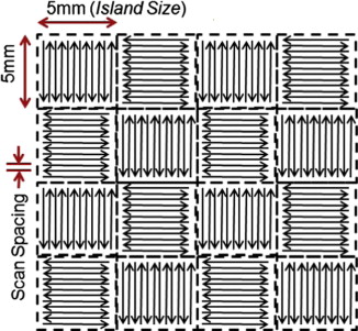
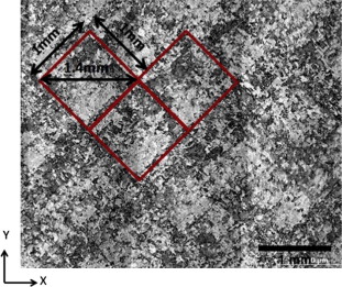
Much like a brickwork bond pattern, the 5mm x 5mm grid is shifted 1mm for each successive layer in both the X and Y dimensions. Interestingly, the crystalline structure of the resulting part varies as you look across the island boundaries. As a result, if you look at a SLM part under a scanning electron microscope, you observe distinct 1mm x 1mm crystalline grids:
In addition, micro-cracking and porosity (which is generally quite low; these parts are commonly around 99.7% dense) follow the same pattern. These effects can be mitigated - indeed, nearly eliminated - by hot isostatic pressing (HIP), and most SLM and DMLS parts are HIP treated by default.
The interesting question for me, though, is how these factors apply to thin-walled parts. My seatmast topper's wall thicknesses are in the neighborhood of 1mm, and thinner in areas. As the authors of this paper note, cracks that are open to the surface of the material aren't always closed by HIP. My suspicion is that the feature sizes at issue here are orders of magnitude smaller than they'd need to be to have a noticeable effect during the lifetime of the part, but only destructive testing (or a better trained material scientist than myself) will bear that out.
I'm also not sure, to be clear, how these crystalline structures compare to those of samples produced via conventional (i.e. non additive) methods. If anyone knows of a good study on the micro-structure of drawn titanium tubing, I'd love to see it!