Manufacturing guy-at-large.

Filtering by Tag: EBM

EBM and chemical surface finishing

Added on by Spencer Wright.

As I've written here before, the field of high performance surface finishes is fascinating - and complex. Surface finish plays a big role in the mechanical and aerodynamic properties of a part, and (in the case of consumer products) it can have a huge effect on marketability too. And so, as I've gone through the process of developing my titanium 3D printed bicycle seatpost, I've been conscious to evaluate many different surface finishing options to find a manufacturing process chain that's both effective and economical.

And so, this past spring, I reached out to Dr. Agustin Diaz to see how REM Surface Engineering could help my parts.

For a bit of context, allow me to quote myself (from EBM surface finishes and MMP):

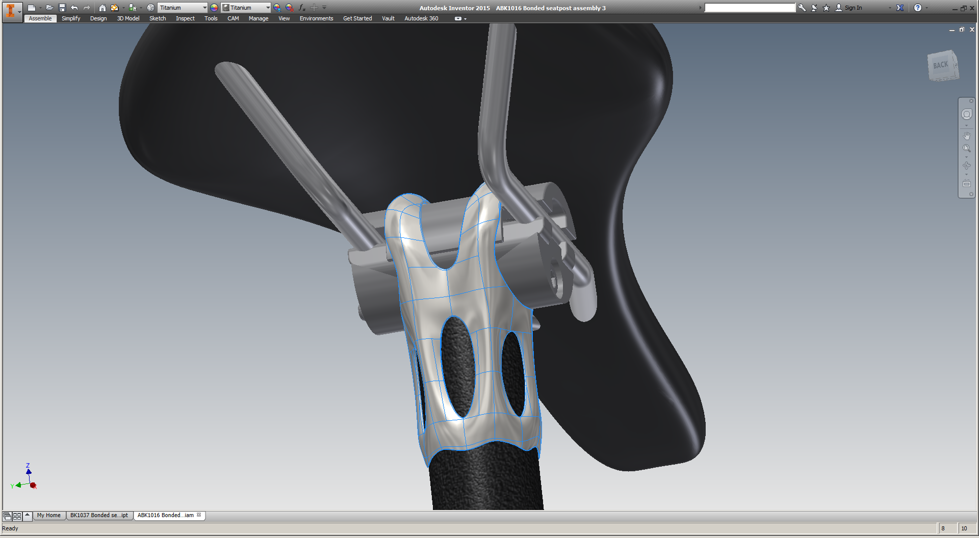
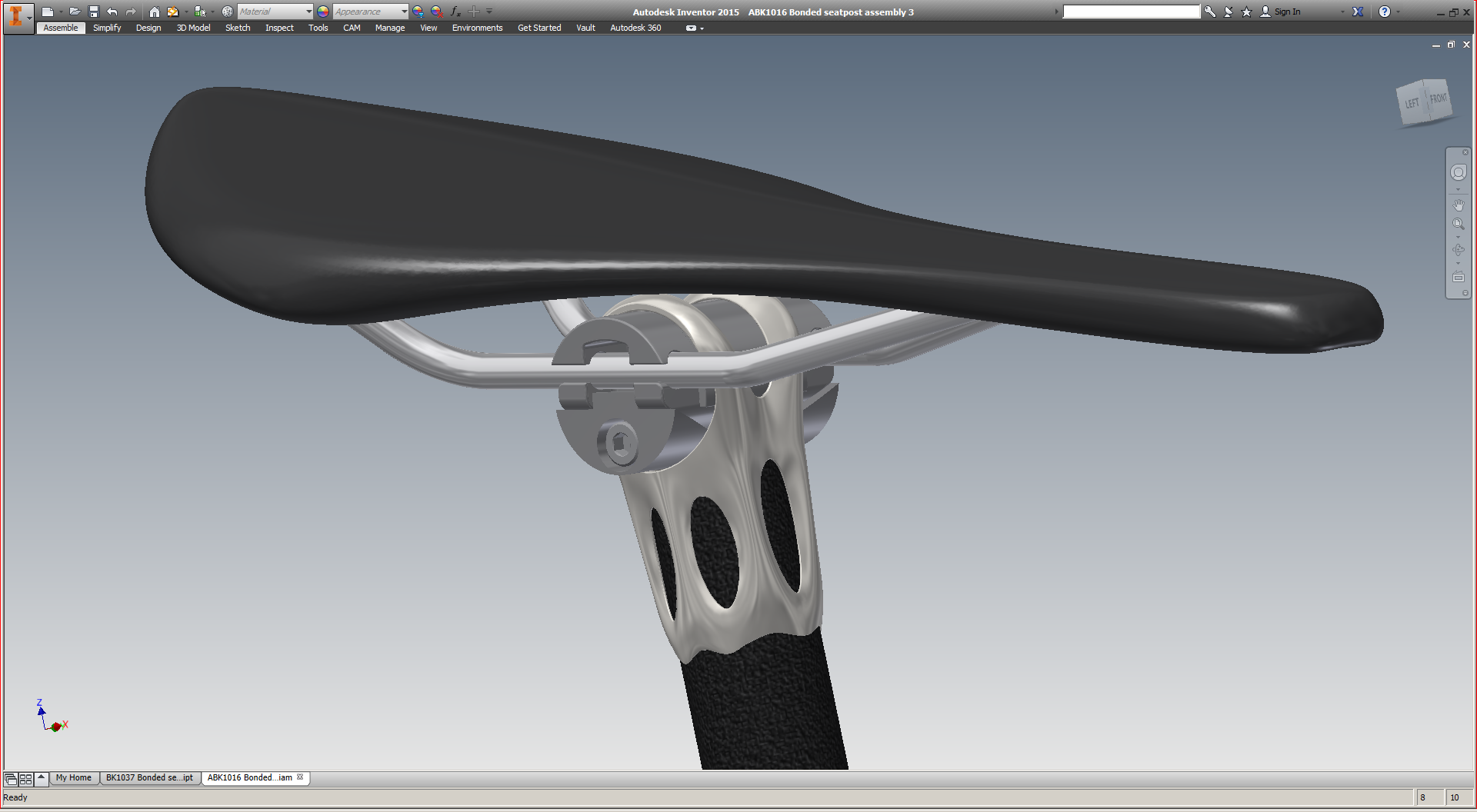
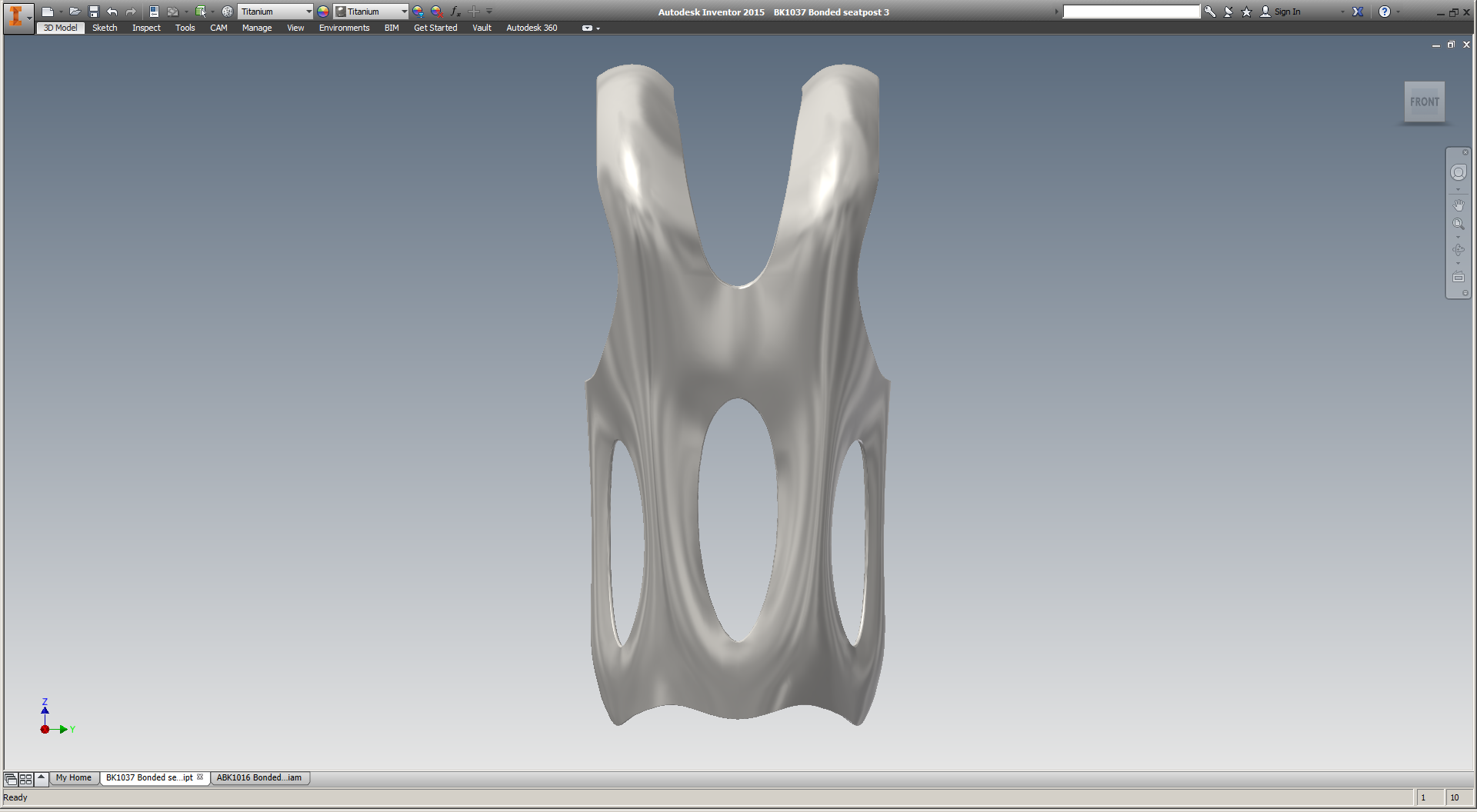
The part's nomenclature

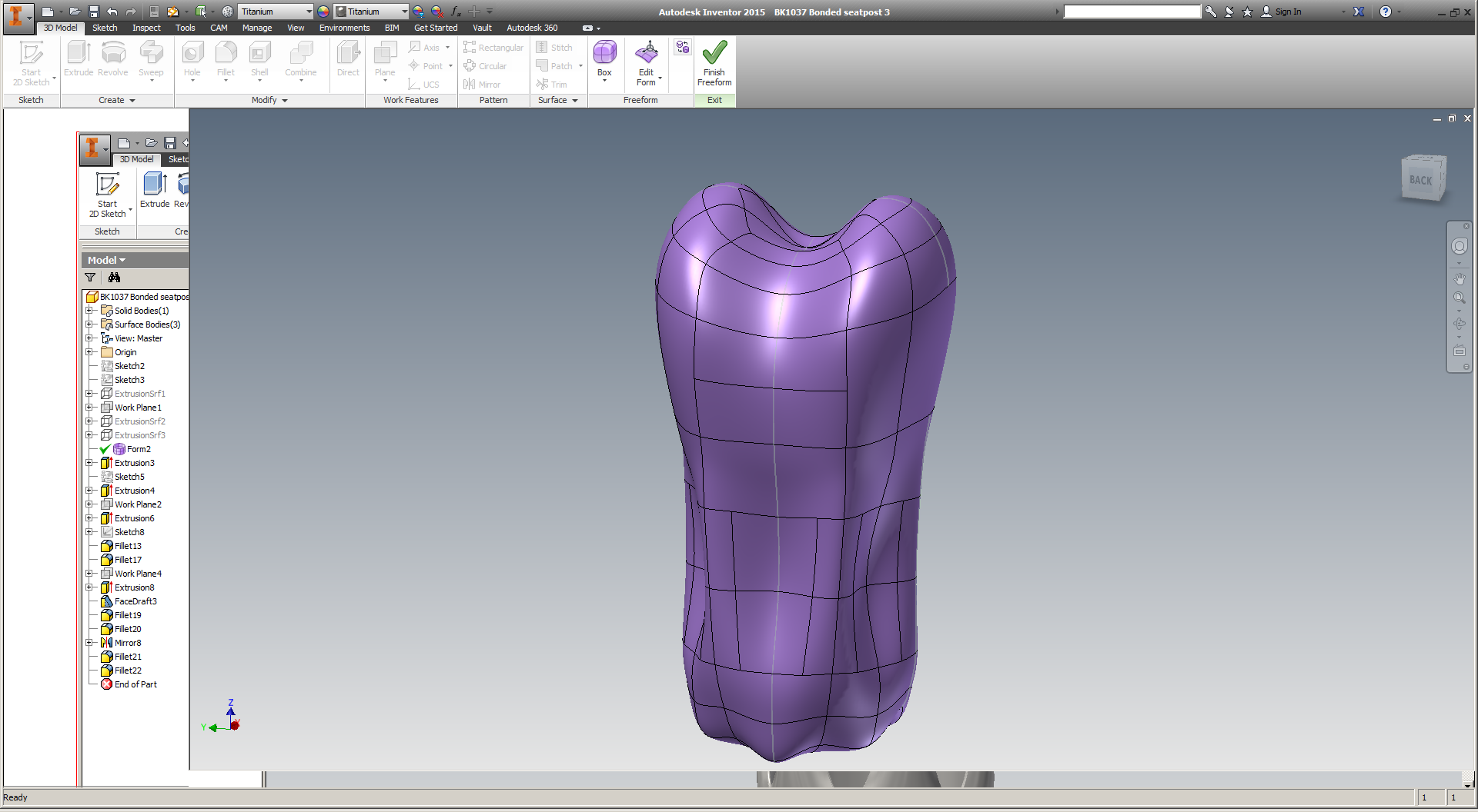
The part in question is the head of a seatpost assembly for high end road bikes. The part itself is small - about 70mm tall and with a 35mm square footprint. As built, it's just 32g of titanium 6/4. Add in a piece of carbon fiber tubing (88g for a 300mm length) and some rail clamp hardware (50g), and the entire seatpost assembly should be in the 175g range - on par with the lightest seatposts on the market today.

As a product manager who's ultimately optimizing for commercial viability, I had three questions going into this process:

  1. How do the costs of the different manufacturing process chains compare? 
  2. How do the resulting parts compare functionally, i.e. in destructive testing?
  3. Functionality being equal, how do the aesthetics (and hence desirability) of the parts compare?

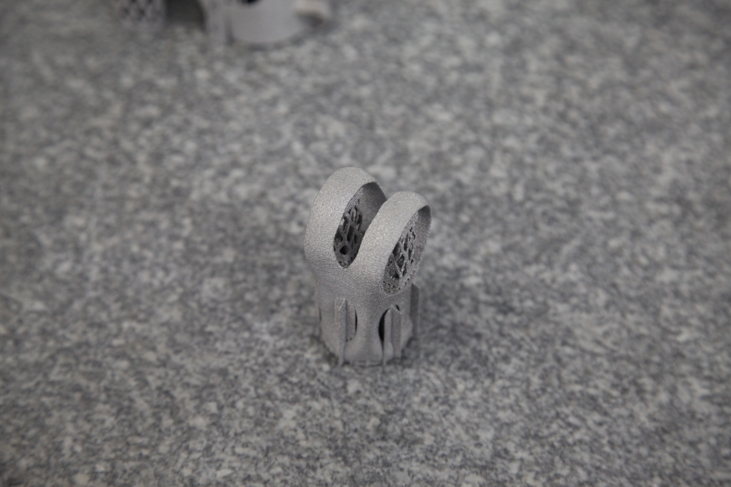
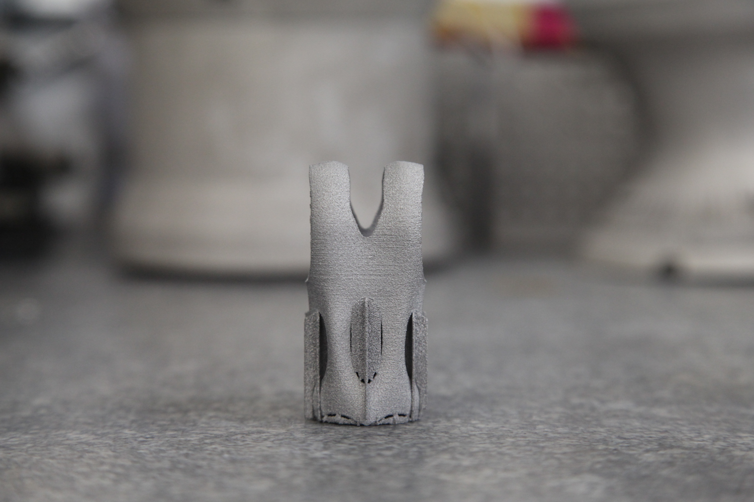
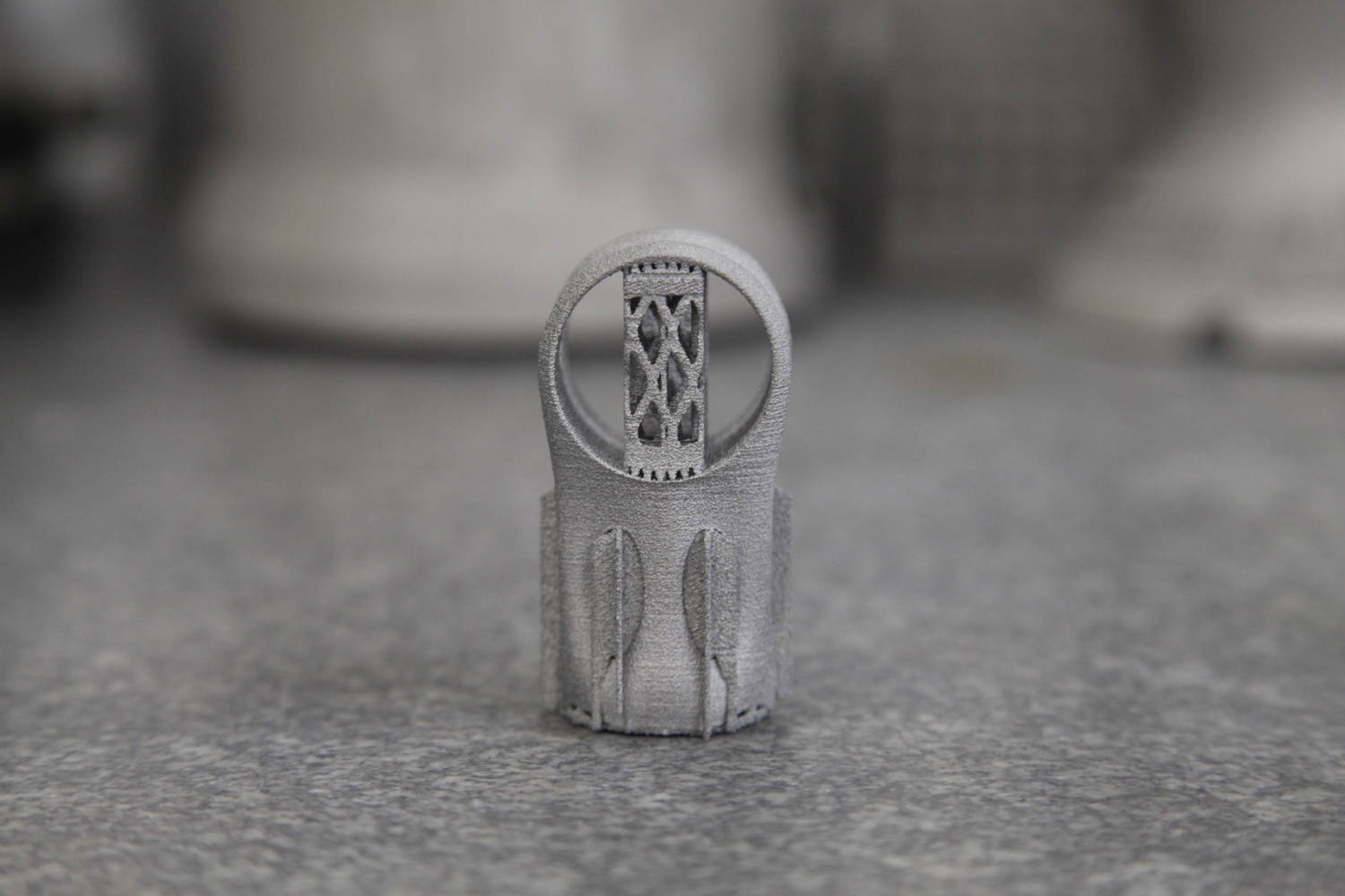
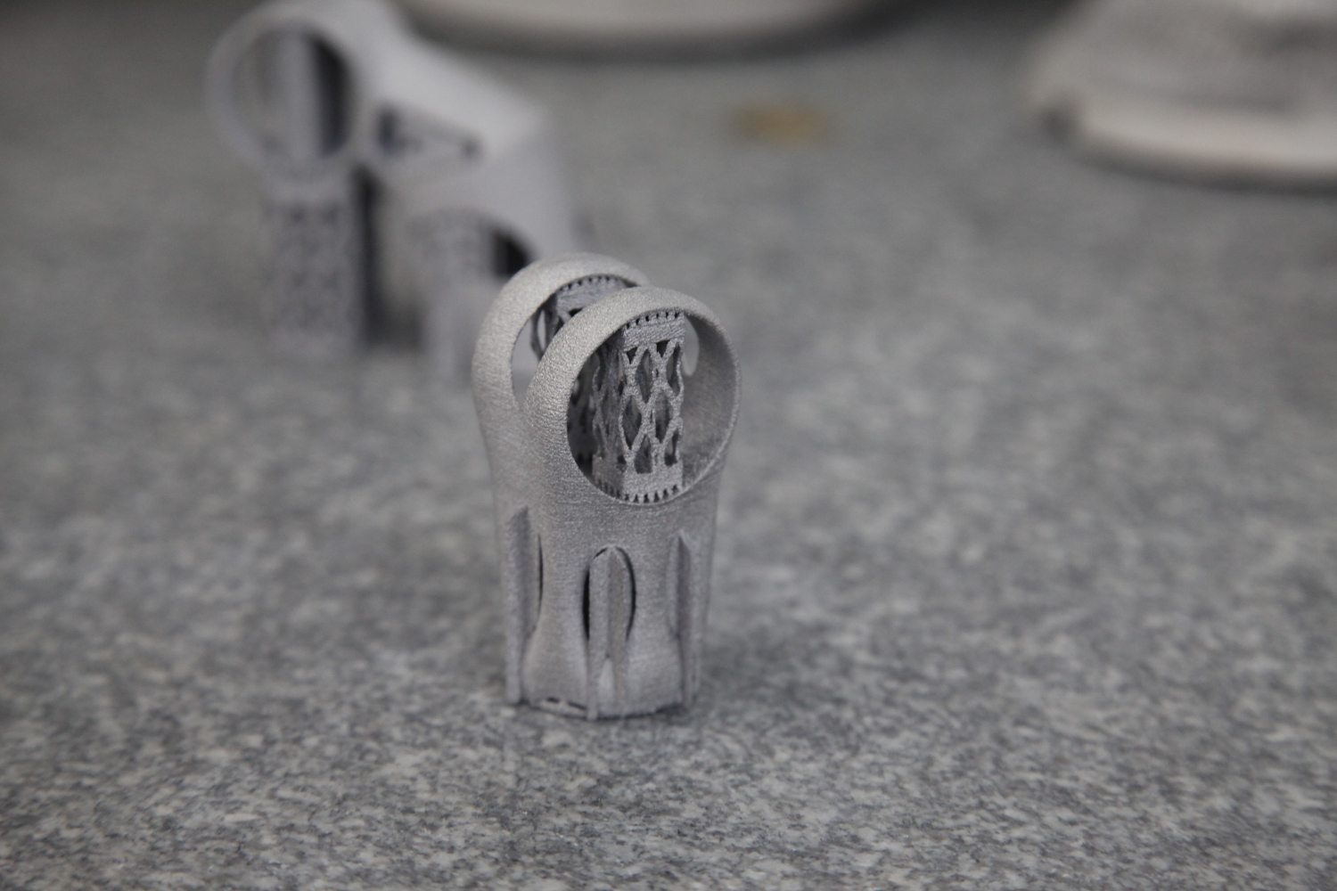
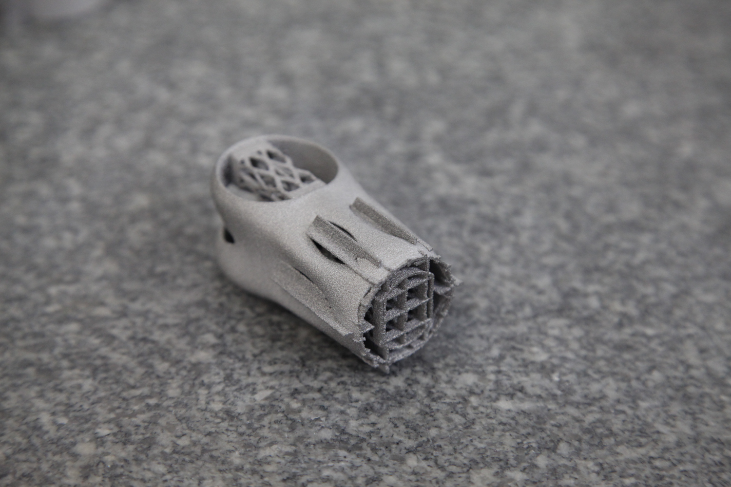
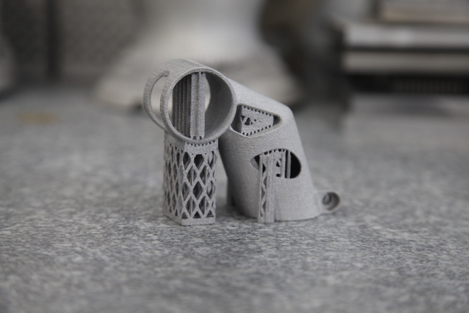
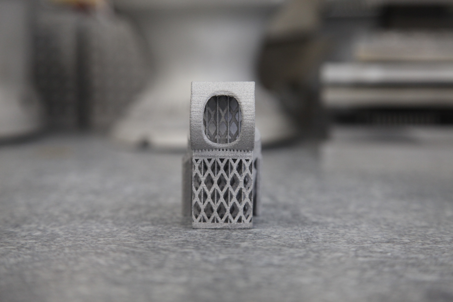
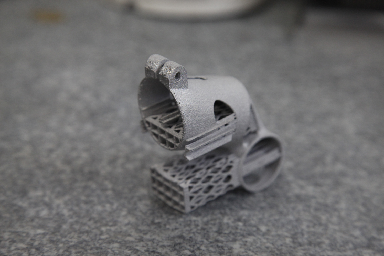
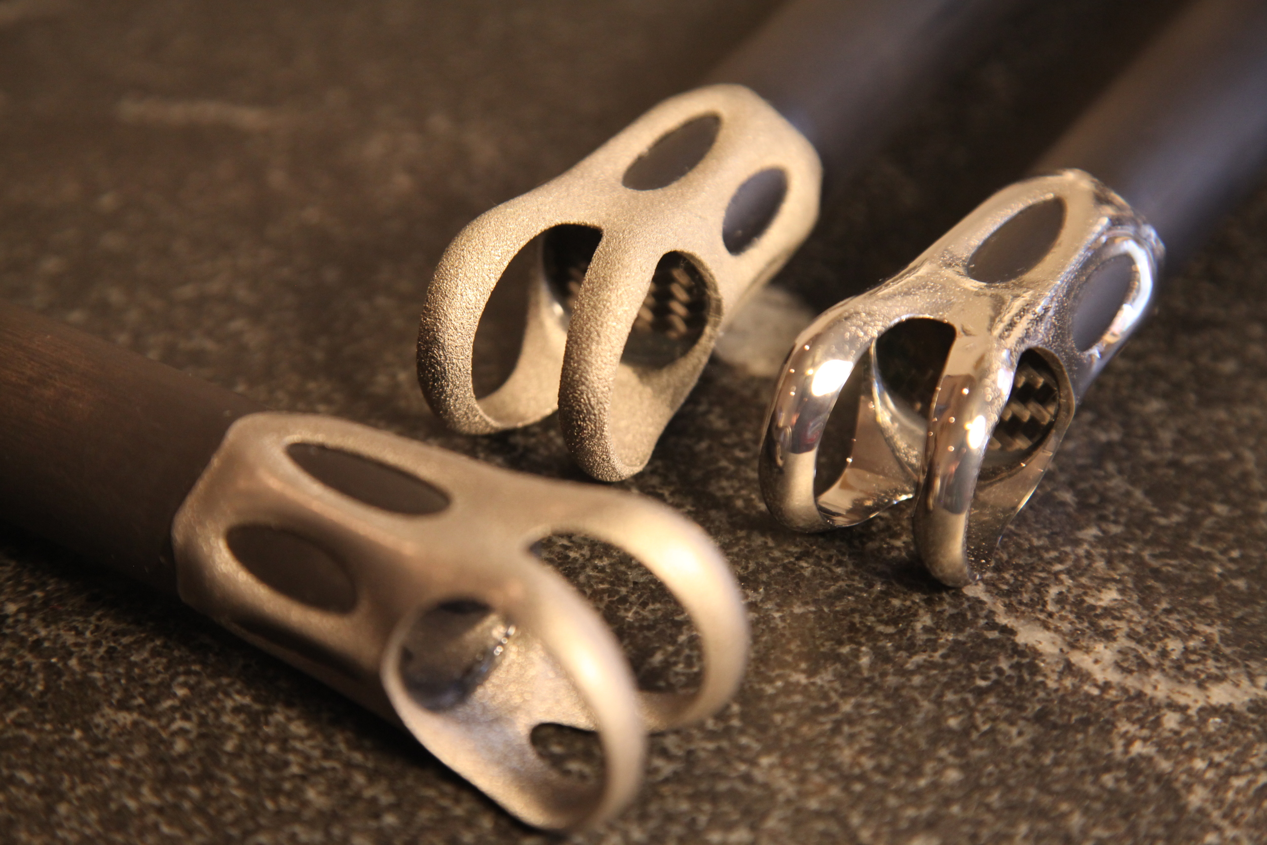
Towards these ends, Dr. Diaz and REM finished three parts for me:

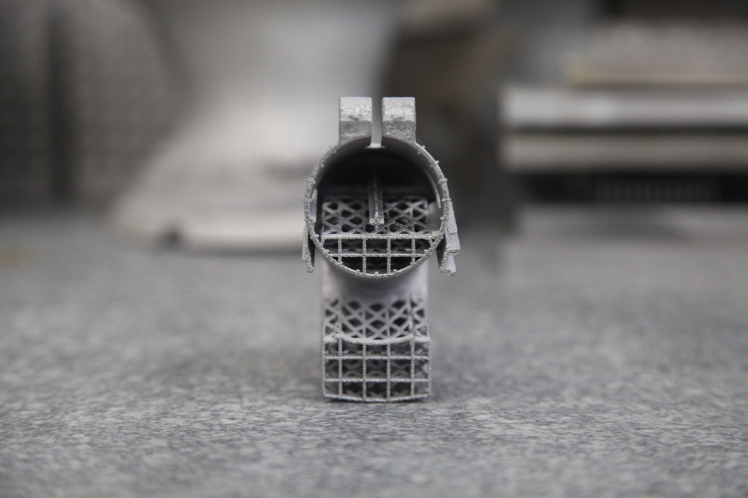
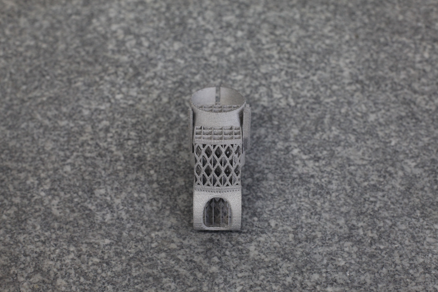
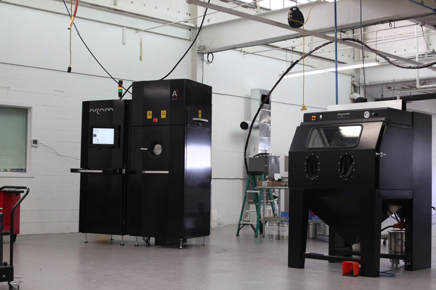
The parts were printed in titanium 6/4 on an Arcam A2X by Addaero Manufacturing. They were then HIP'd (hot isostatic pressing is a whole other area of interest - more on it soon, I hope) before being treated by REM's isotropic superfinishing process.

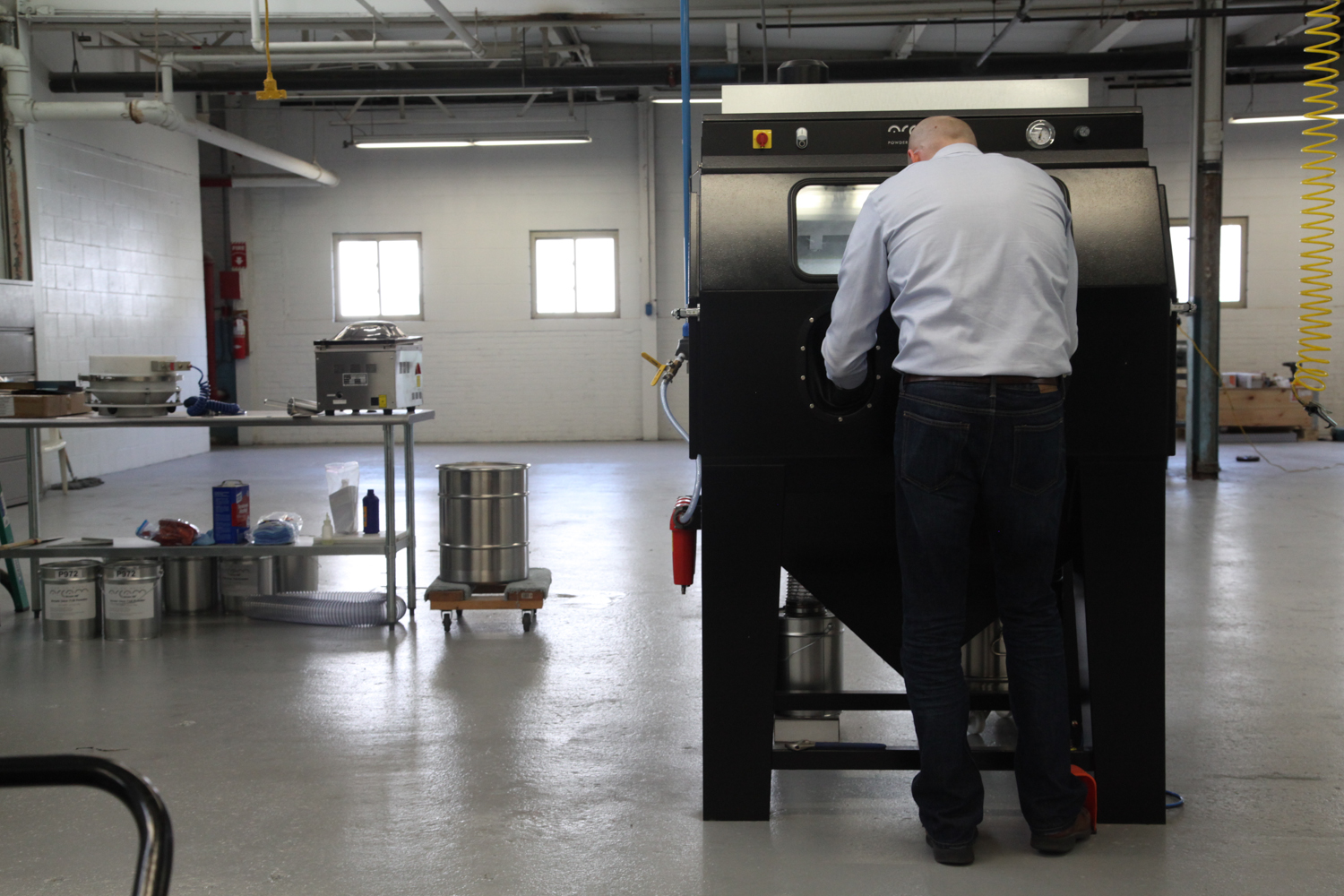
The results are very interesting, and contrast in many ways with MicroTek's MMP process. REM ISF is a chemical accelerated vibratory finishing process. In it, parts are placed in vibratory finishers with a nonabrasive media and a chemical activating agent. The chemical agents are selected by the part's composition: Different metal alloys will react to different chemicals. The media, on the other hand, is selected depending on the part's geometry: Parts with small features will require smaller media, etc.

As with any vibratory finishing process, then, REM tunes the frequency and amplitude of the machine to adjust the aggressiveness of material removal. The media chambers in these machines are shaped like toruses, and parts take a rotating helical path around them as they vibrate. Adjusting the frequency and amplitude of the vibration affects that helical path, and REM tunes the rolling angle to produce the result that's needed. "It's an art and a science," Dr. Dia zaddtold me.

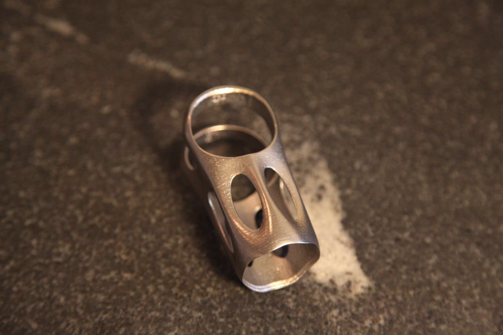
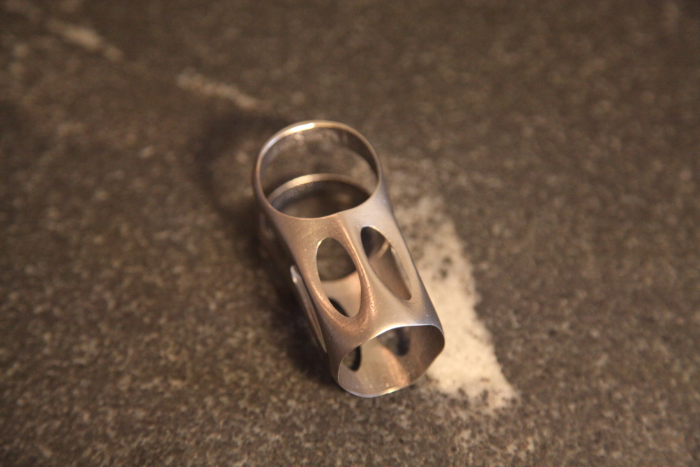
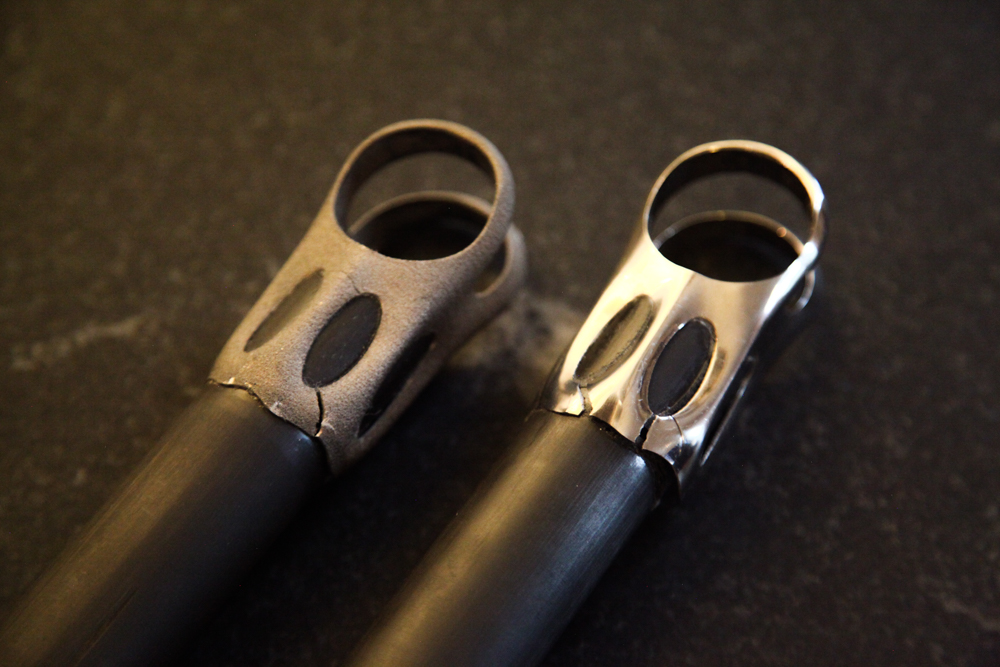
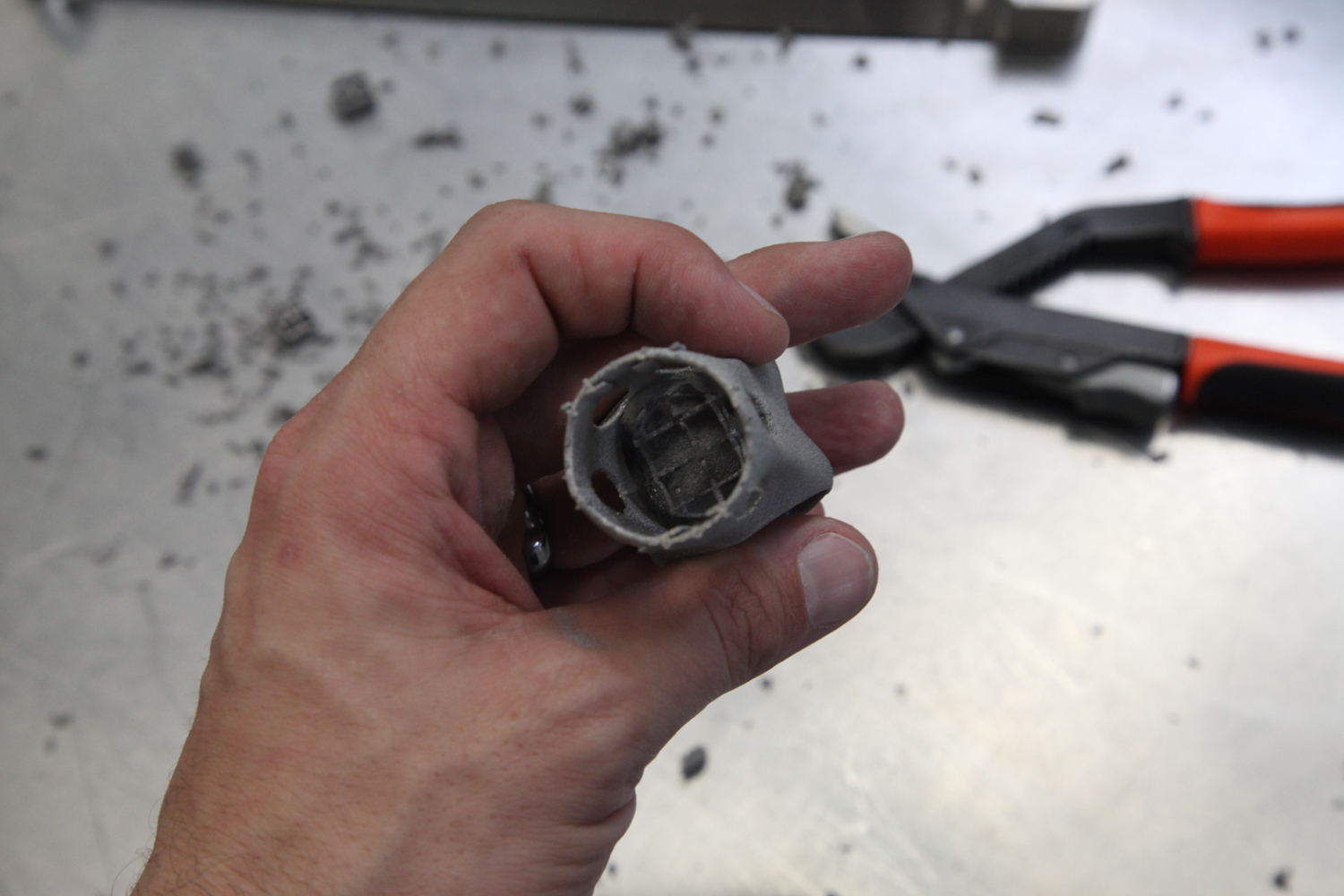
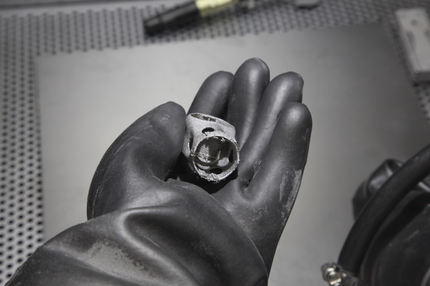
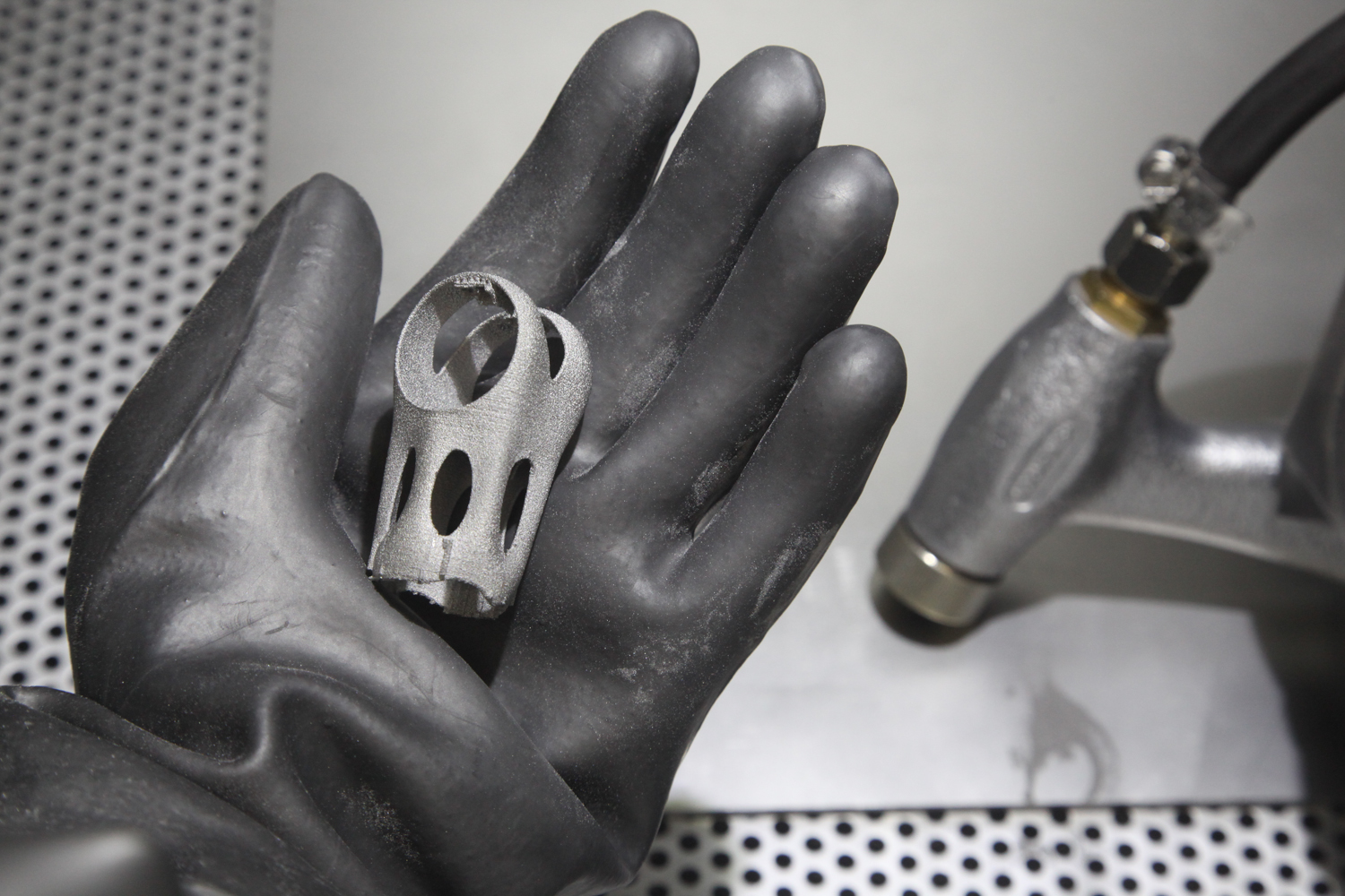
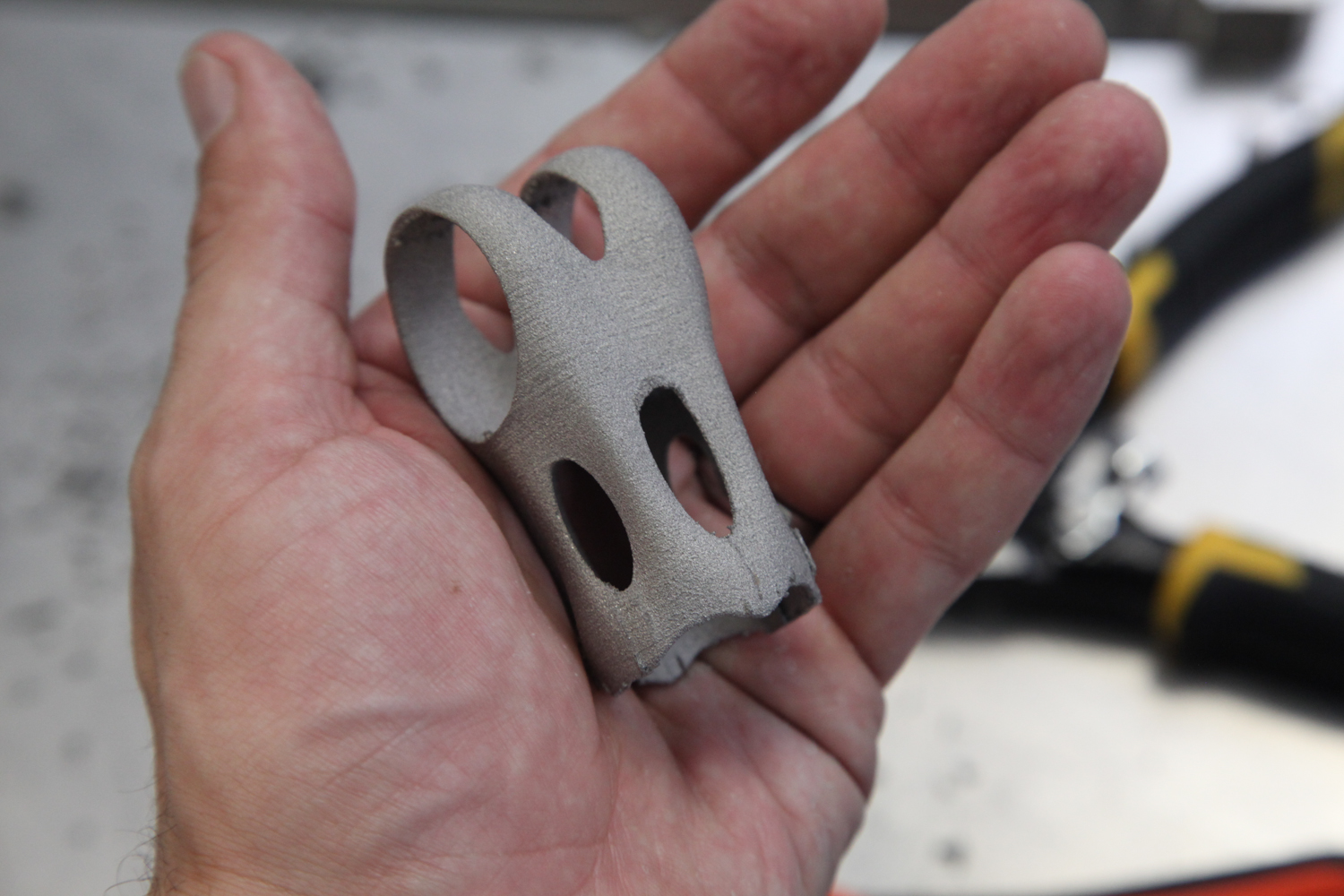
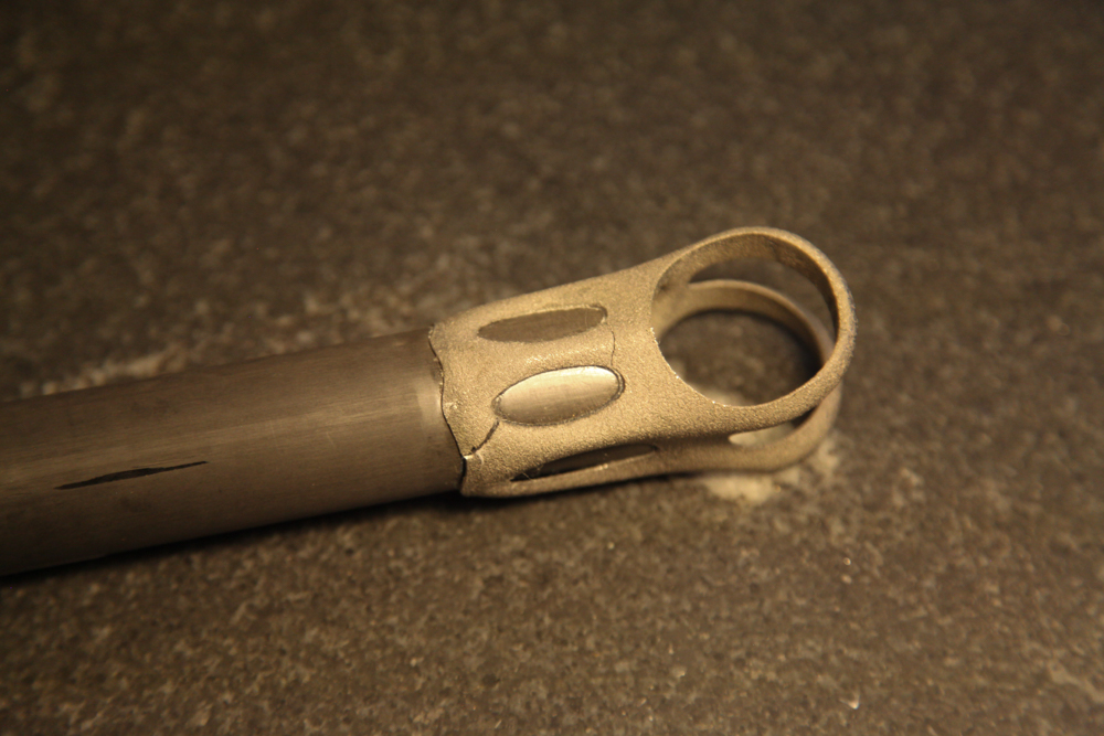
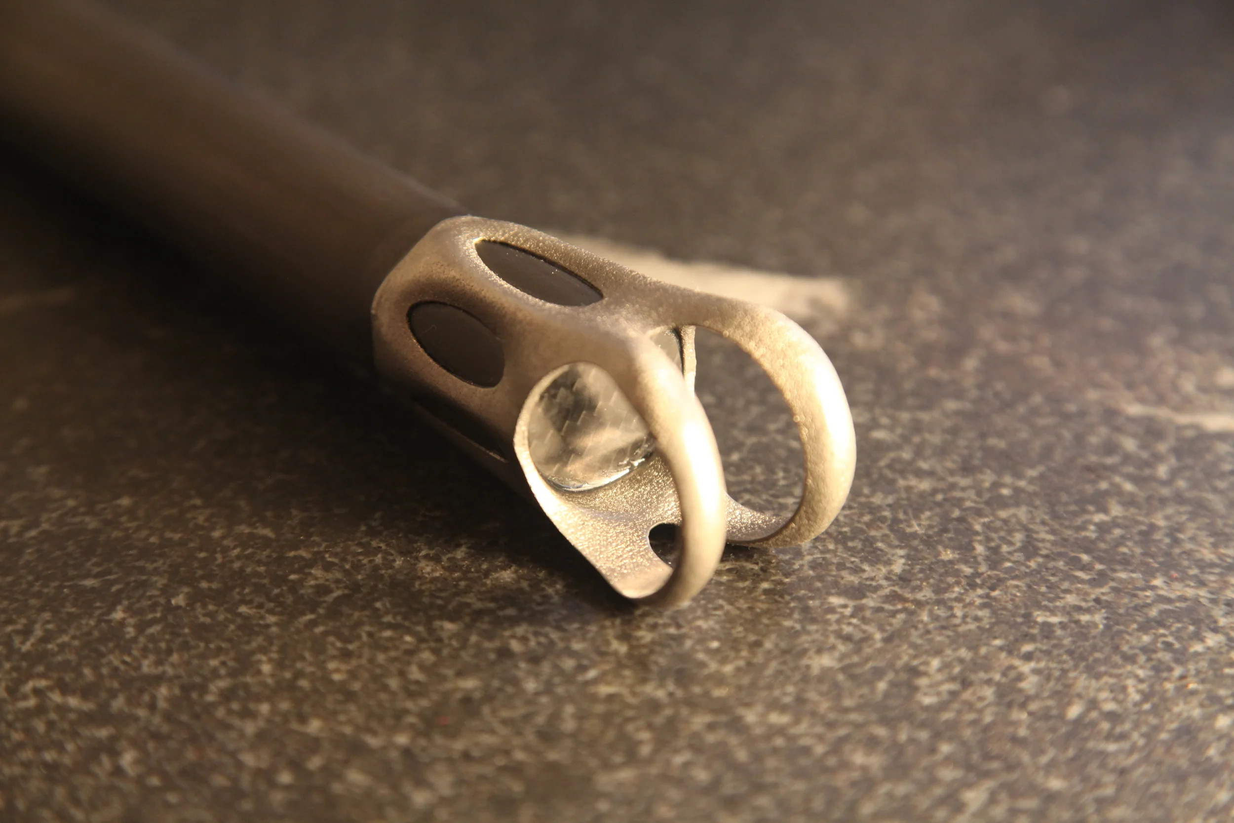
REM finished three parts for me, in two slightly different design variations. The first part went through their Extreme ISF process - a quick treatment that removes excess powder and some higher-order roughness. The second two parts went through Extreme ISF *and* an additional ISF treatment, removing .020" (about .5 mm) and producing a much smoother surface. In order to compensate for the material removal, one of the Extreme ISF + ISF parts was printed with .020" of  extra stock on all of its surfaces (if you look closely, you can see the additional stock as a stair-stepping effect on the inside of the skirt edge). The results are below - click on the photos to enlarge.

Incidentally, I found REM's process nomenclature a bit confusing at first. As described above, all of these processes include some chemical agent and some media. The difference in the different processes has to do with the balance of those two factors: Extreme ISF uses aggressive chemistry but relatively little media interaction, whereas ISF is a longer process with less aggressive chemistry and more media interaction. REM also offers a Rapid ISF process, which is to ISF much as a lathe is to a milling machine. In it, the parts are fixtured and then moved through the chemical/media mixture. It's a much faster process, but one which requires more tooling and setup and hence is reserved for high volume parts.

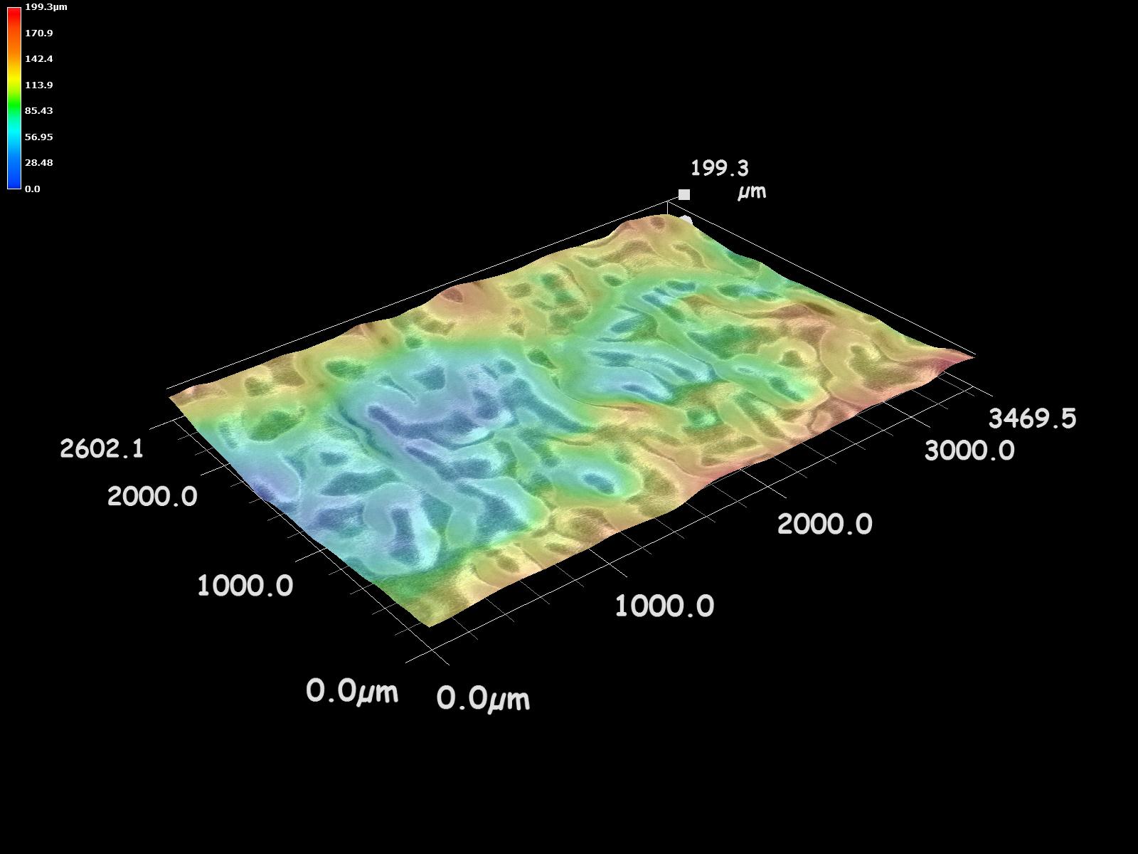
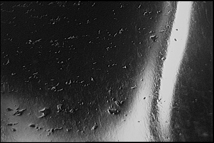
The surface character of the REM parts differs significantly from the parts that I had MMP'd. ISF interacts with the full surface of the part, with the result being that both peaks and valleys are rounded out. Note that the color scale in the images below are not constant; click on the images to see the color scale key.

The roughness values for the two methods are also quite different. The key metrics are below; full roughness profiles & filter data are here for Untreated, Extreme ISF, and Extreme ISF + ISF parts (thanks to REM).

Ra - Roughness average

All values in µm. Evaluation length = .5"

Rq - Roughness, root mean square

All values in µm. Evaluation length = .5"

Rsk - Roughness skewness

All values in µm. Evaluation length = .5"

Rt - Roughness total

All values in µm. Evaluation length = .5"

As with most things, the numbers above both a) capture interesting differences between these five finishing methods, and b) are abstractions which ultimately fail to capture the entirety of the physical parts. Such is the nature of data; in and of itself, it's not particularly insightful.

As I've described previously (and above), my interests are functional, aesthetic, and economical. The latter two of these sit more or less in balance, but the former is bound by the composition & arrangement of matter. To that point, Agustin referred me to a paper by Kwai Chan called "Characterization and analysis of surface notches on Ti-alloy plates fabricated by additive manufacturing techniques," which shows a correlation between notch depth and a shortened fatigue life in EBM parts. To quote:

The presence of surface notches is likely to promote crack initiation and reduce the fatigue performance of LBM and EBM materials. Since the depths of the surface notches correspond to the maximum valley depths on the surface, fatigue life of the various Ti–6Al-4V materials is expected to decrease with increasing maximum Rvm values...
To improve fatigue performance, the surface notches on the EBM and LBM materials must be removed by machining.

Of course, those last two words - "by machining" kind of begs the core question that I'm asking here. To wit, see the Rvm numbers from REM:

Rvm - Maximum valley depth

All values in μm. Evaluation length = .5".

The goal, here, is to improve fatigue life - and avoid the fate that my last parts met during testing. My hope - and one that's balanced by my lingering concerns about my glue joint design - is that the much reduced Rvm numbers here will help significantly.

More soon.

Notes on Arcam and SLM

Added on by Spencer Wright.

Yesterday, GE announced that they had put in bids to acquire both Arcam and SLM for a combined total of $1.4B. This move poses some interesting questions about the next few years in industrial AM, and will no doubt have a big impact on both the companies involved and their customers and competitors. I don't have any privileged insight into any of these companies' decision making process, but I have a longstanding interest in the industry and what they're working on. Here are a few observations & questions that occurred to me about the deals and their impact.

Background

In 2012, GE Aviation made three large acquisitions in industrial AM. The first was the combined purchase of Morris Technologies and Rapid Quality Manufacturing, two sister companies based in Cincinnati who had already been a big supplier to GE Aviation (terms of the deal were not disclosed). Later that year, they bought Avio Aero, and Italian parts supplier, for $4.3B. These two purchases showed an interesting balance in technologies. While Morris and Avio had very similar business models (both were job shops that produced parts for GE Aviation and other business units; Avio also produces parts by traditional manufacturing methods), they focused on different additive technologies: Morris on laser, and Avio on EBM.

I've written about the difference between laser and EBM in the past, but a few points here:

  • The fuel nozzle that GE is so famous for printing is made by laser in Auburn, Alabama on EOS machines. I believe that their (lesser known) T25 temperature sensor is made on the same machines.
  • The laser (Note: I'm using "laser" here to refer to processes that are variously called DMLM, SLM, DMLS, lasercusing, and the generic "laser metal powder bed fusion." Note also that SLM can be used to refer both to the printing process AND to the machine manufacturer that GE just acquired.) machine market has a number of providers: Aside from EOS and SLM (the two machine manufacturers that GE is most known for using) there's Renishaw, Concept Laser, Additive Industries, 3D Systems, and a variety of Chinese entrants.
  • While GE Aviation has tended towards EOS machines (see the video above), GE Power & Water uses machines made by SLM in their Greenville, SC plant (Note: Here I'm drawing from an AMUG 2015 and other industry sources; sorry for the lack of a hyperlink reference).
  • Arcam sits apart from these: it's currently the only company making machines for EBM (electron beam melting, or "electron beam metal powder bed fusion" if you're picky).
  • Avio Aero has done some really interesting things with EBM since the GE acquisition. Perhaps most notably, last year they printed low pressure turbine blades out of titanium aluminide, an intermetallic alloy. TiAl has excellent mechanical properties at high temperatures (an important feature of any part that's in the hot stage of a jet engine), and is traditionally cast by companies like Precision Castparts Corp (PCC). Printing in TiAl brings advantages but is extremely difficult due to the material's tendency to fracture. Printing TiAl could be a big deal as GE ramps up production of TiAl blades for the GEnx engine, and it was very interesting to note that after the successful prints, Avio bought an additional ten Arcam systems - the largest purchase that Arcam had ever accepted.

So: GE already had a strong portfolio in additive. What are the implications of the Arcam and SLM acquisitions, and how will this impact the industry?

A full stack, in-house

The most interesting part of the acquisition to me is the fact that GE will now be able to in-house the entire industrial AM supply chain (minus software; more on that below). Previously, they were focused primarily on basic research and applications development (Morris, Avio, CATA, and the Niskayuna Global Research Center) and serial part production (Auburn, Greenville, and Avio). Now, they'll own not one but two machine manufacturers - allowing them to push upstream and make a more direct impact on the development of the additive industry.

But perhaps more importantly, GE gains both powder production (through AP&C, the Canadian powder supplier that Arcam acquired for CAD 35MM in 2014) and final parts manufacturing (through DiSanto, the medical implants manufacturer that Arcam acquired for $18.5M later the same year). When Morris was acquired, they shut down their sales organization and focused on printing parts for internal GE customers. DiSanto is a very different business, though, and I wonder whether it might make sense as part of GE's healthcare unit - with its traditional focus on medical imaging and healthcare IT.

AP&C is a bit of a different beast. They manufacture the raw materials for not only powder bed fusion but also MIM, HIP, and other powder metallurgy applications. Their website advertises commercially pure titanium and ti64, but Arcam also markets cobalt-chrome - which both the fuel nozzle and the T25 sensor housing are made of. I'll be very curious to see whether AP&C continues selling powders to the public, or if they focus on internal use.

Improving - and selling - manufacturing machines

Separate and apart from the implications to GE's internal operations, I'm particularly interested in the way that GE's involvement at these new levels of the tech stack will affect how the industry matures. Try though they may, it's difficult for a company whose bottom line depends on selling machines (as opposed to, say, selling machines AND printing parts, or selling machines AND developing manufacturing software) to truly impact the end-to-end engineering process much. And while GE has been at the forefront of additive research (and, no doubt, collaborates very closely with both their hardware and software providers), I'm hopeful that having them at the helm will push both EBM and laser powder bed fusion forward in a cohesive way. 

Some might suggest that keeping expertise in house would be the strategic choice here, but I disagree. Powder bed fusion today suffers from both a lack of talent (easiest to change by expanding the number of use cases for the process, many of which GE ultimately is not going to compete on) and a lack of process predictability and reliability. GE has more knowledge about improving AM part yield than just about anyone else in the world, but that doesn't mean that there aren't other approaches that they're not trying. Inasmuch as sharing whatever process improvements they come up with will encourage others to try their own approaches, I hope that GE does just that. And they have in the past: through their involvement with standards and industry organizations like America Makes, 3MF, and ASTM F42; through their participation in sessions at AMUG and RAPID, and through their open innovation work (some of which I worked on while at Undercurrent) with GrabCAD and NineSigma.

My hope would be that GE continues to market and improve both SLM and Arcam machines. The latter is particularly dear to me, as EBM equipment isn't currently made by anyone else (and because I've had many parts printed on Arcam machines). SLM is a bit different, as the market for laser powder bed fusion is already so rich. But by that same rationale, the potential impact that any updates to SLM's machines would have could be huge, as they would force other players to respond in kind.

Software

I take GE at their word: They want to be a contemporary engineering company, and they believe that contemporary engineering companies need formidable software capabilities. And if they're going to truly make their mark with a software solution, it would be wise to do so in a realm where they know the problems well.

Even before these acquisitions, GE knew the pain points in additive as well as anyone else. Adding a few machine manufacturers, plus a raw materials supplier and a finished parts manufacturer, will only help that along. So my question is this: Why wouldn't GE make a play in additive manufacturing software? This is, after all, the whole subtext behind the Brilliant Factories initiative: GE knows how hard it is to make things, and they can help you make them better.

As you'll know from my previous writing, I'm excited for advances in build processing (see netfabb and Magics), build simulation (see 3DSim and Pan Computing, and research by Wayne King at LLNL), and in-process monitoring & control (see Sigma Labs, plus the product spec sheets for a *lot* of the current class of laser printers). Each of these is extremely hard in itself, and recreating the entire stack would be extraordinarily complex; I don't expect any one company to solve (or even attempt) them all. But whether they build their own solutions or work with external providers to build them, GE will be a huge stakeholder in the next generation of additive manufacturing software. And if they're serious about being a formidable software company, then why wouldn't they take a shot at building it themselves?

Regardless of how these acquisitions shake out, the next year should be interesting. I'm looking forward to it :)

The first 14mm

Added on by Spencer Wright.

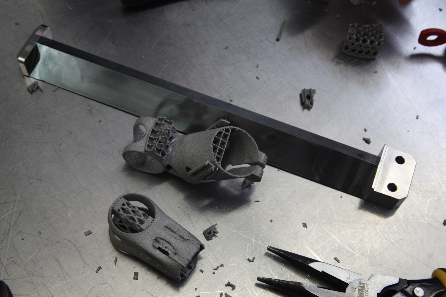
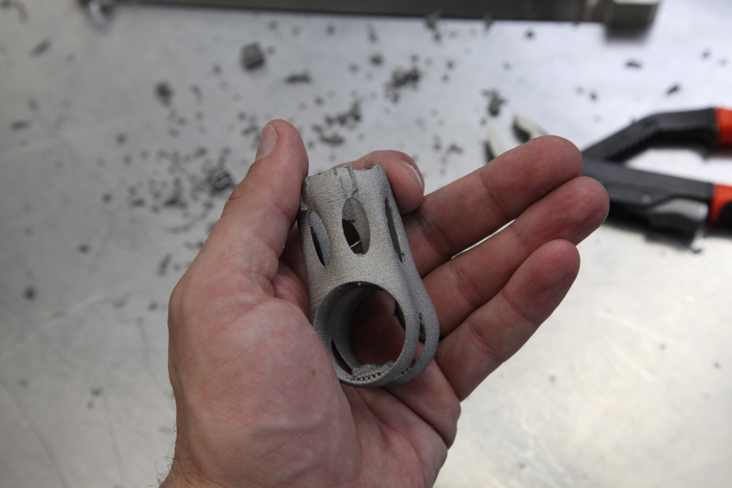
This week I got some good news: Researchers at The MTC had begun printing one of my latticed bike stems.

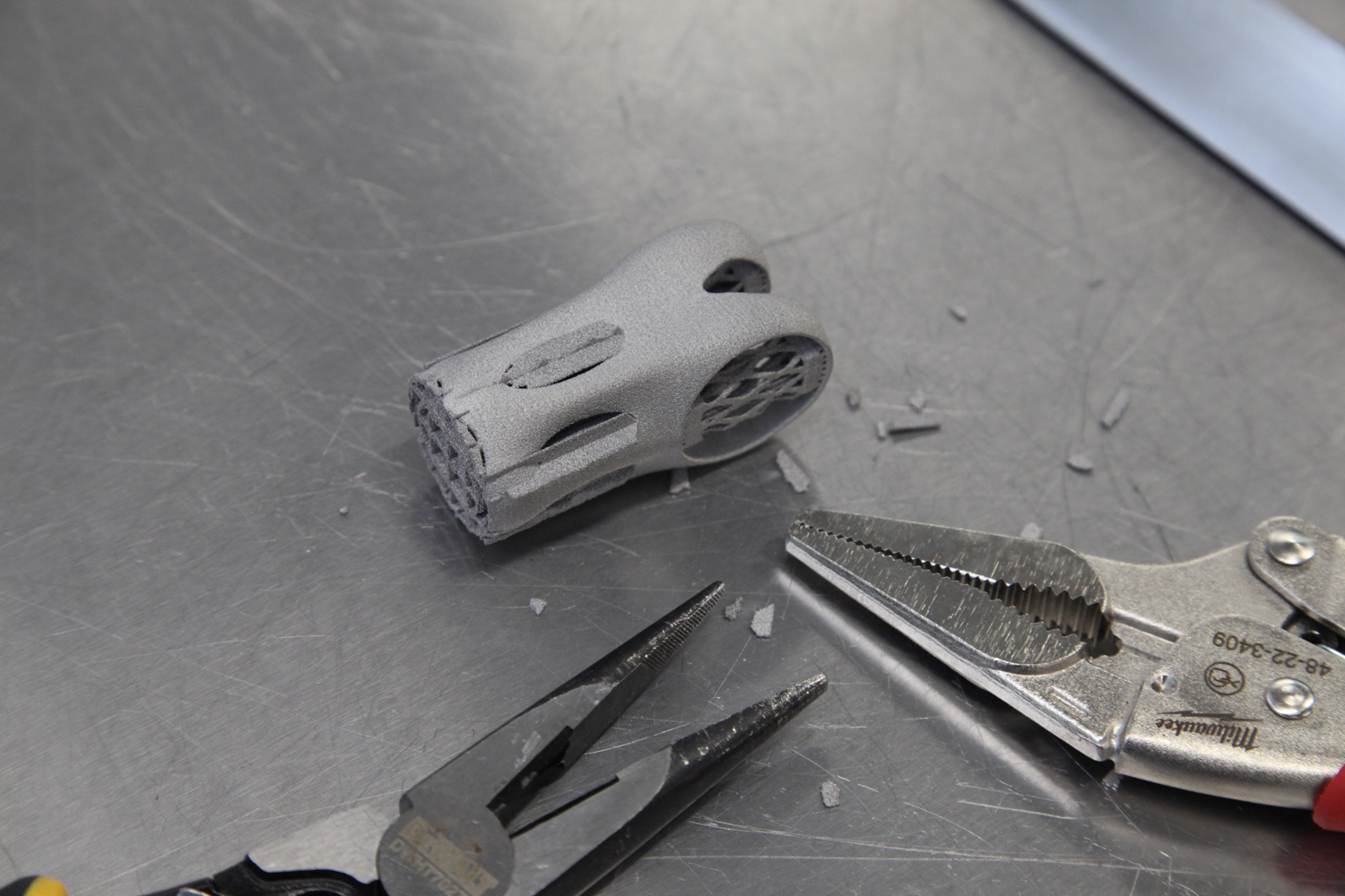
The first 14mm of my latticed bike stem, printed in titanium on an Arcam A2x. The part is upside down (relative to the build orientation) in this photo.

This part was printed in titanium 6/4 on an Arcam A2X. Unfortunately the build failed at 14mm high; on the upside, it appears that the failure was *not* caused by my part. It's a bit early to make any judgments about its feasibility, but I'm pleased to see that these beam diameters (which are between .8mm and 1.8mm) seem to print without support structures. As you can see below, many of them (almost all, in fact) had very low angles relative to the XY plane.

The build orientation of my latticed bike stem.

I'm hoping to have more progress on this soon. Thanks to my friends at The MTC for their help with printing - and with debugging the design!

Seatpost testing post-mortem

Added on by Spencer Wright.

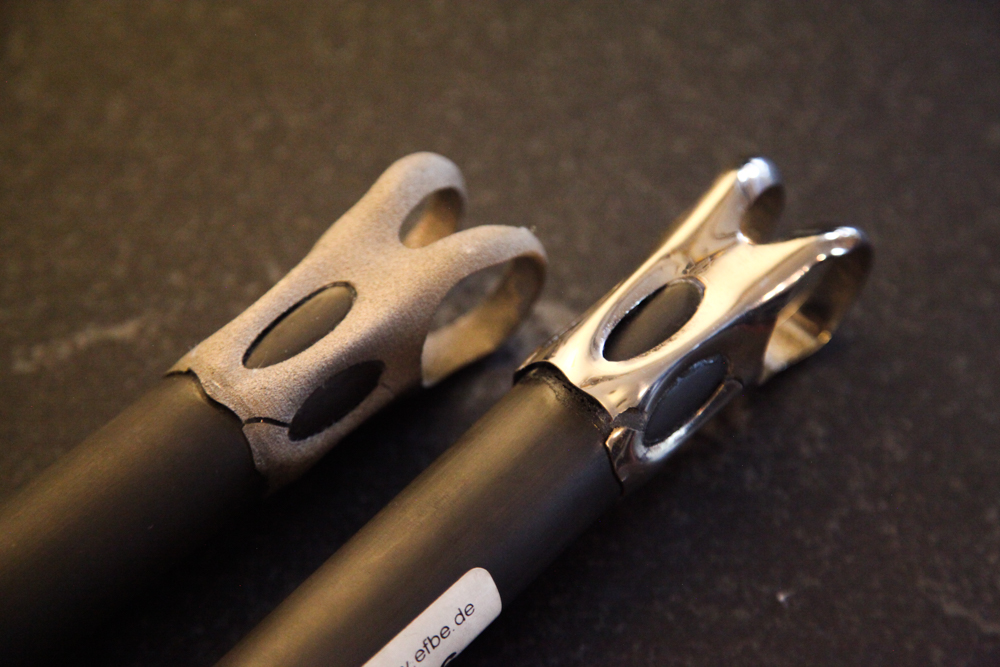
This week I got my seatposts back from testing at EFBE. As you'll recall, these failed ISO 4210-09:2014, 4.5.2. 

The part's nomenclature

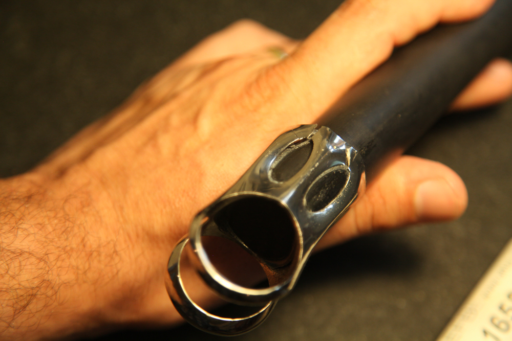
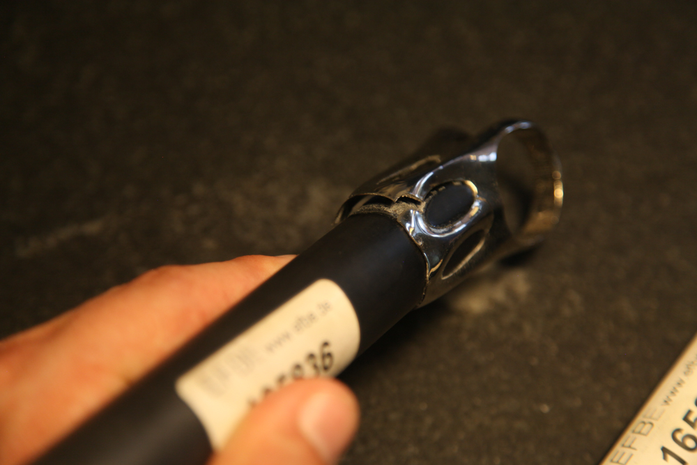
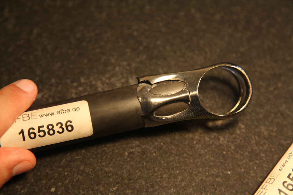
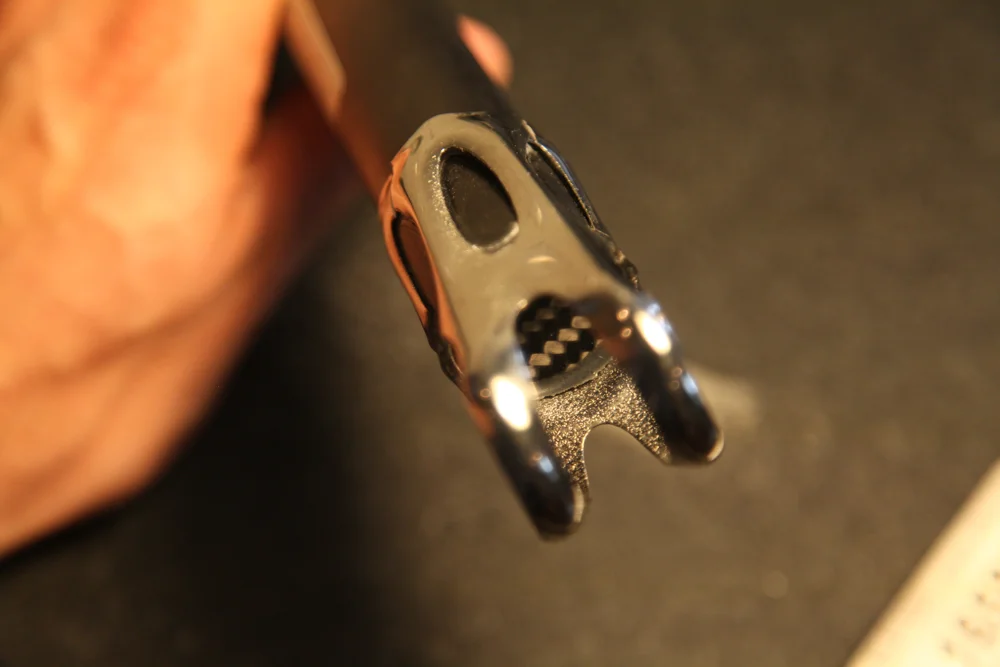
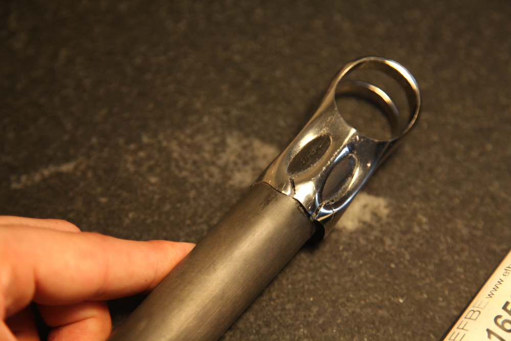
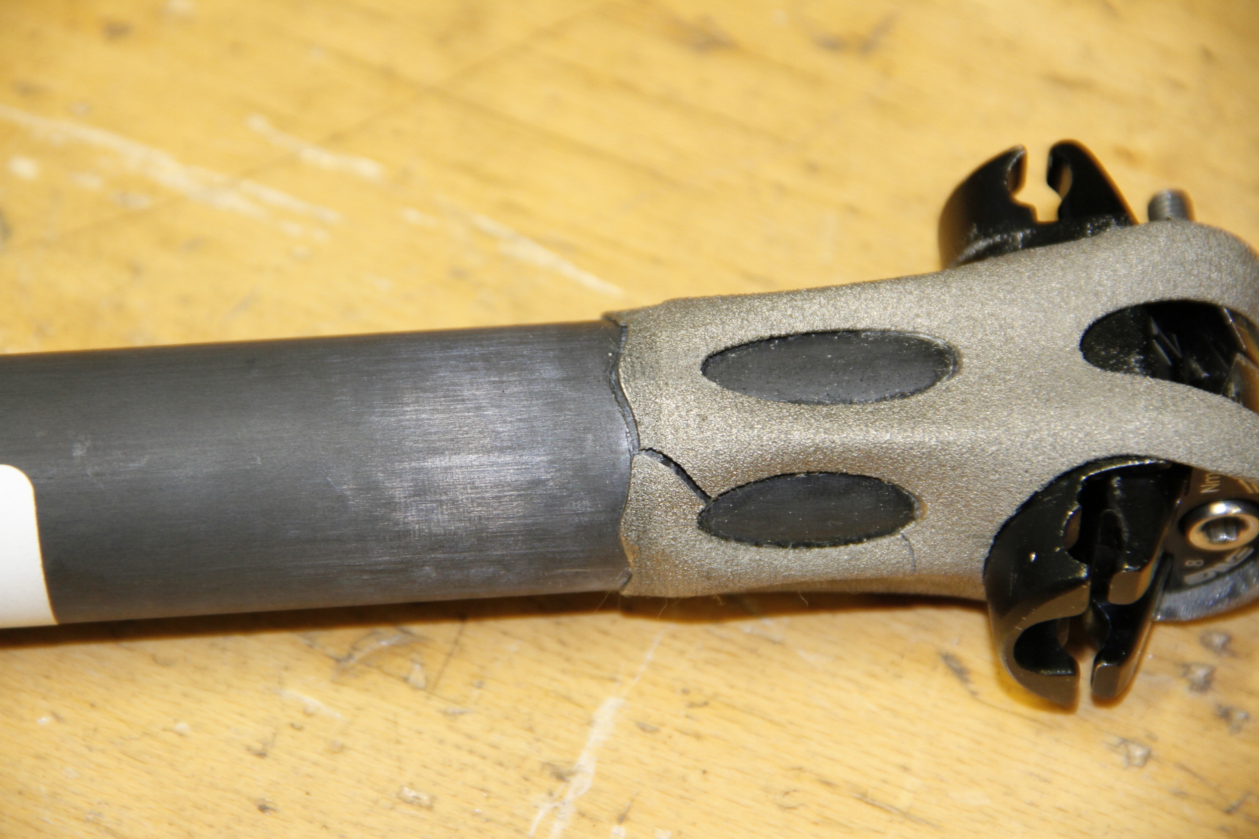
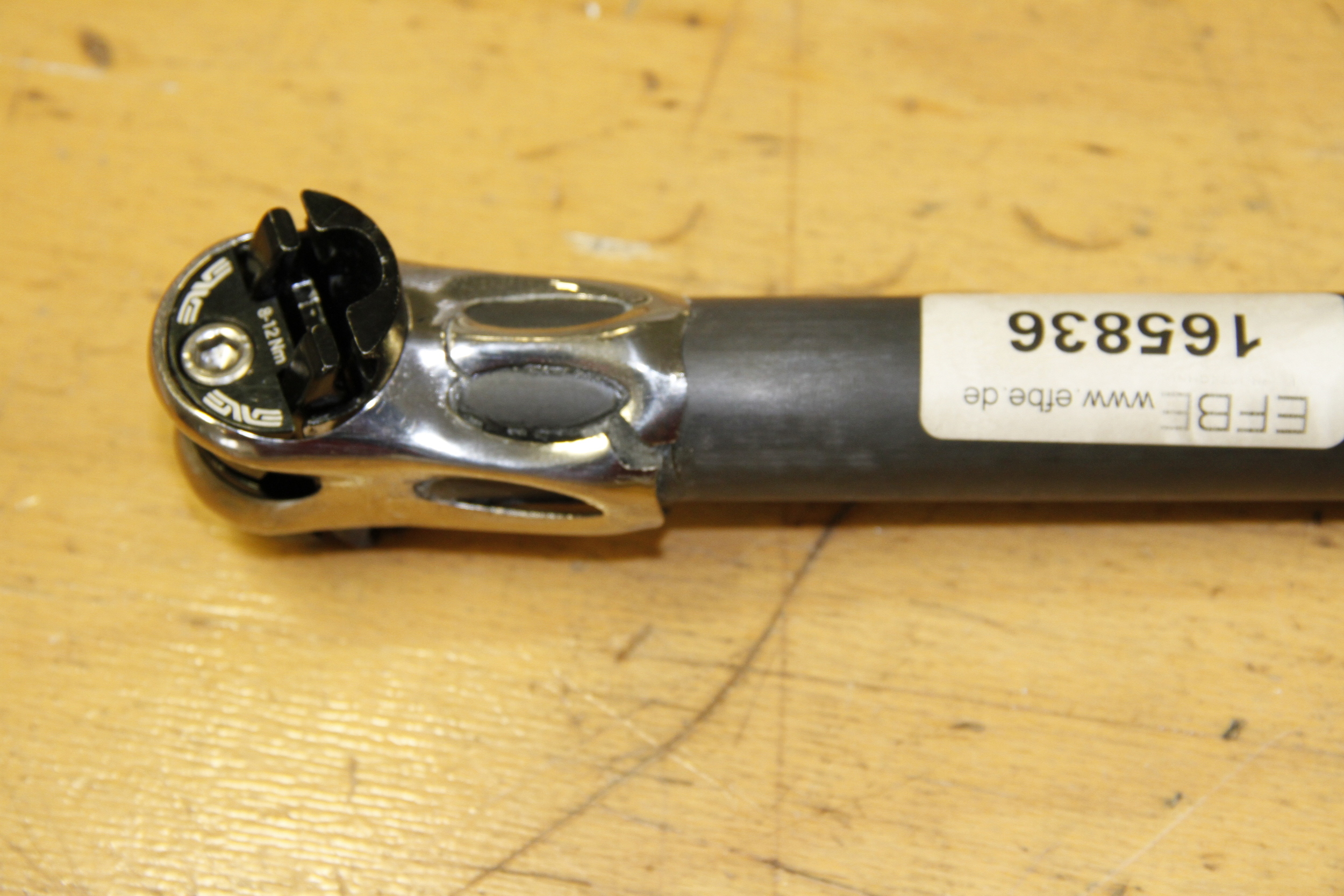
Both seatposts failed in essentially the same way: The shoulder straps rotated backwards, breaking the skirt in two locations and cracking both of the side legs as well. The front of the skirt separated completely from the carbon fiber post at the bottom, and the top/front of the seatpost cylinder appears to have slipped upwards (sheared) as well.

The "BLING" part (see this post for details on the difference between the two samples) failed slightly before the as-printed version, at 70,770 cycles. It's a bit hard to tell in the photos, but there are definitely some areas where I didn't have enough glue to form a complete bond. Part of this is operator error (i.e. my fault for not assembling the seatpost well), and part of it is engineer error (i.e. my fault for not designing the seatpost so that it could be assembled by any grease monkey). 

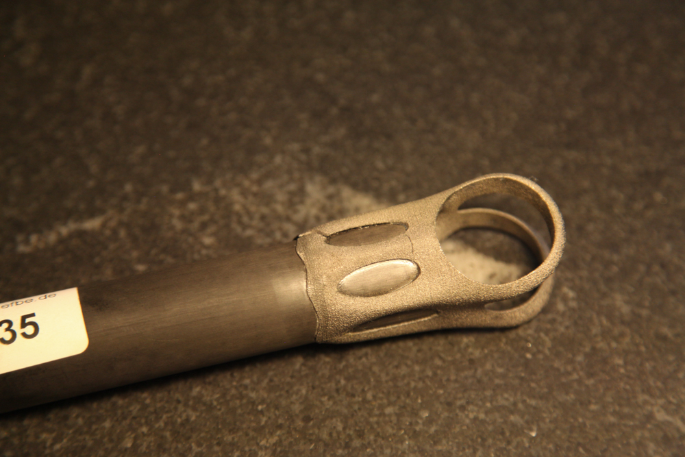
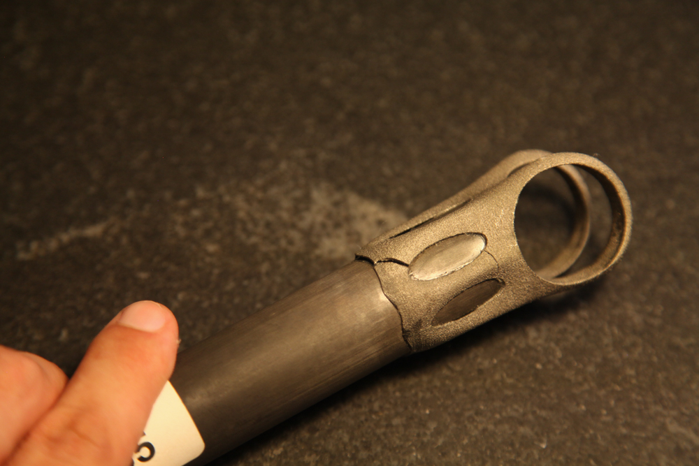
The as-printed part failed a bit later, at 80,904 cycles. Again, close inspection shows that the glueline had many defects.

I take a few lessons from this:

First, it's clear that my assembly design needs to be improved. It's possible that the part still would have failed with a better glue joint, but at this point in my process it's important that I'm able to isolate possible issues - and variations in bond quality makes that *really* hard. I suspect the best approach here is to make the glue cavity captive, such that during assembly the uncured adhesive is forced to fill the full volume between the seatpost head and the carbon fiber post.

This likely means eliminating the windows from the seatpost cylinder. It also means either creating a double lap shear joint (like Robot Bike uses) or making the joint blind on both sides (by capping the end of the carbon post, which I did on this assembly, *and* closing the top of the seatpost cylinder, which I didn't do). 

Second, I should probably be HIPing these parts - at least until I've isolated everything else and determined whether, and how, HIP affects performance.

Third, I'd like to dial in the inner diameters of both the seatpost cylinder and the saddle clamp cylinder. The latter can probably tolerate a bit of play, but the former directly affects the glueline and should probably be controlled more tightly.

On the upside: The failure mode on these parts wouldn't have hurt the rider, whereas failure in the shoulder straps could have been dangerous. In addition, I've got a chance to try this again - with the parts that REM treated for me recently. I won't be able to change the original design at all, but I can at least try to see whether a change in technique can improve the glue joint.

Regardless, it's good to get tested parts back. More soon!


Note: Thanks to Addaero Manufacturing for printing these parts, and to MicroTek Finishing for finishing them!

Seatposts, tested

Added on by Spencer Wright.

Today I got word from EFBE that two of my EBM seatpost had been tested - and failed.

These are the as-printed and the "bling" samples (see this blog post for details); they failed after 80,904 and 70,770 fatigue cycles (at 1230N), respectively. As a result of their failure, I decided to not test the third "fatigue resist" part.

I'll write up a longer description of the results soon, but two thoughts here:

  • These parts were *not* HIP treated - which might possibly have helped their fatigue resistance.
  • It appears that some delamination occurred between the printed parts and the carbon fiber post, which makes me question whether the glueline itself was faulty. If so, it's possible that by improving my glue joint I could have relieved some stress from the printed part. Regardless, I will note that the glueup process was kind of a pain in the ass - and I'd like to redesign that anyway.

As it happens, I have three more of these parts on my desk now. They *were* HIP treated, and I intend to glue one of them up and send it for testing. It won't be a perfect 1:1 test (these parts were treated by REM Surface Engineering, through a different process than MicroTek uses), but the results will be interesting at the least :)

Onwards!

Seatposts assembled

Added on by Spencer Wright.

Before I send these three seatposts out for testing, a quick update:

The seatpost heads (which I wrote a detailed post on a few months ago) are now glued to carbon fiber posts. I also added a thin carbon fiber disc to the top of each of the posts, so that water can't get into the bike's seat tube. The whole thing was assembled using 3M DP420 epoxy.

These are headed back to EFBE this week, where they'll go through the same ISO test as my seatmast topper was subjected to. More details soon!

EBM surface finishes and MMP

Added on by Spencer Wright.

When I visited MicroTek Finishing, a Cincinnati based precision finishing company, in late 2014, I was intent on printing my seatmast topper with laser powder bed fusion. DMLS's install base is relatively large, making it easy to source vendors and compare pricing. And while their surface finish and dimensional accuracy can leave something to be desired, DMLS parts can be put into service with minimal post processing.

But as I was saying goodbye to Tim Bell (my host at MicroTek) that afternoon, he planted a seed. I should try building my parts in EBM, he said - and see if MicroTek's MMP process could bring the rough parts up to a useable state.

That same day, I asked Dustin and Dave (both of whom I worked with on my seatmast topper) what they thought of the idea. Dave had extensive experience on an Arcam A2, and thought it was definitely worth trying out. Relative to DMLS, EBM is a quick process (for more details on Arcam and EBM, see the Gongkai AM user guide), and a big portion of the cost structure of metal AM parts is the amount of time they take to print. Furthermore, parts can often be stacked many layers high on EBM machines, allowing the fixed costs of running a build to be distributed over a larger number of parts. And while EBM parts do tend to be rough (and have larger minimum feature sizes than DMLS), they also tend to warp and distort less - making the manufacturing plan a bit simpler in that respect.

Shortly after that trip, I reached out to Addaero Manufacturing. I visited them soon after, and then asked if they'd be interested in exploring an EBM->MMP process chain. They were, and provided three identical parts to experiment on.

The part in question is the head of a seatpost assembly for high end road bikes. The part itself is small - about 70mm tall and with a 35mm square footprint. As built, it's just 32g of titanium 6/4. Add in a piece of carbon fiber tubing (88g for a 300mm length) and some rail clamp hardware (50g), and the entire seatpost assembly should be in the 175g range - on par with the lightest seatposts on the market today.

As a product manager who's ultimately optimizing for commercial viability, I had three questions going into this process:

  1. How do the costs of the different manufacturing process chains compare? 
  2. How do the resulting parts compare functionally, i.e. in destructive testing?
  3. Functionality being equal, how do the aesthetics (and hence desirability) of the parts compare?

I'll write more about the second point later; in this post, my primary aim is to introduce MMP and compare the different process chains from a financial and operational standpoint.

Basics of surface texture

As confirmed by a 1990 NIST report titled Surface Finish Metrology Tutorial, "there is a bewildering variety of techniques for measuring surface finish." Moreover, most measurement methods focus only on the primary texture - the roughness itself - and incorporate some method of controlling for waviness and form. From the same report:

The measured profile is a combination of the primary and secondary texture. These distinctions are useful but they are arbitrary in nature and hence, vary with manufacturing process. It has been shown, but not conclusively proven that the functional effects of form error, waviness and roughness are different. Therefore, it has become an accepted practice to exclude waviness before roughness is numerically assessed.

Surface finish is usually measured using the stylus technique:

The most common technique for measuring surface profile makes use of a sharp diamond stylus. The stylus is drawn over an irregular surface at a constant speed to obtain the variation in surface height with horizontal displacement.

The most common surface texture metric is Ra. (For a good, quick, technical description of the varieties of surface texture metrics, see this PDF from Accretech.) Ra measures the average deviation of the profile from the mean line (the related Rq also measures deviation from the mean line, but using a root mean square method), and is used across a variety of industries and manufacturing methods. But it's incapable of describing a number of important aspects of a part. For instance, it's critical (for both aestetic and functional reasons) that my parts have Rsk (skewness) values close to zero - meaning that their surfaces are free from flaws like pits and warts. In other words, I'd take a consistent, brushed surface over one that's highly polished but has a few deep cuts/pits.

I should note, of course, that surface finish is a result of the total manufacturing process chain. If the near net shape part (straight out of the EBM machine) is rough and pitted, then it'll be difficult to ever make it acceptable - and the methods required to do so will vary widely. 

MicroTek and MMP

MicroTek is just one in an international network of companies that perform MMP, which grew out of a Swiss company called BESTinCLASS Industries. The MMP process is closely guarded; neither MicroTek nor BiC disclose enough about the process to really understand how it works. From MicroTek's website:

MMP Technology is a mechanical-physical-catalyst surface treatment applied to items placed inside a processing tank.  MMP technology is truly different from traditional polishing processes because of the way it interacts with the surface being treated.
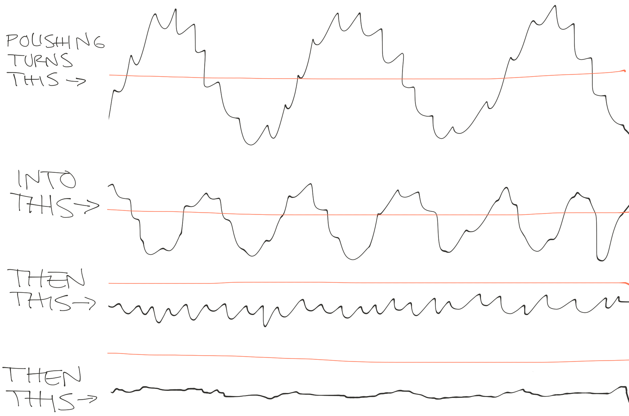
MMP Technology uses a mechanical cutting process at a very small scale (not an acid attack or any other process that could alter the part's metallurgical properties), meaning it can distinguish between micro-roughness and small features. The process actually maps the surface as a collection of frequencies of roughness, removing first the highest frequencies, then removing progressively lower frequencies.
Unlike other polishing processes, MMP Technology can stop at any point along the way, so now for the first time it is possible to selectively remove only the ranges of roughness that you don't want on the surface, giving you the option of leaving behind lower frequencies of roughness that could be beneficial to the function of the part.

To hear Tim and JT Stone tell it, MicroTek essentially does a Fourier transform on the topography of the part. They analyze the surface finish as the combination of many low and high frequency functions, and begin the MMP process by characterizing those different functions and identifying which ones to remove. Then, by selecting "an appropriate regimen of MMP Technology from the several hundred treatments available," they selectively remove the undesirable aspects of the surface finish - while still preserving the underlying form of the part.

This is worth highlighting: traditionally, polishing is a process whereby a part is eaten away by abrasive media. With each successive step, progressively smaller scratches are made in the part's surface. You're constantly cutting down the peaks of the part, and as a result the form gets smaller and smaller over time. With MMP, you have the flexibility to remove fine frequencies while keeping longer ones - maintaining the original intended shape.

The parts

Addaero printed three identical parts for me. I sent two to MicroTek. They processed one for fatigue resistance, and the other they "made BLING."

(Note that you can click on the photos above to see a larger version.)

MicroTek sent detailed inspection reports with the parts, and the picture they paint is fascinating. MMP reduced both Ra and Rq drastically, and Rt dropped significantly as well. Rsk is a bit of a different story, however: in one of the measurement locations ("Side of leg"), it dropped well into the negative range. You'll recall that the absolute value of skewness is really the issue here; a negative number (indicating pitting) is just as bad as a positive (indicating warts/spikes) one.

I've put the raw data in a Google Sheet, here; the full inspection reports are here and here. The charts below show most of the relevant information, broken down by the area of the part being tested. A helpful description of the part's areas ("V-neck face," etc) is here.

Ra - Roughness average

All values in μm

Rq - Roughness, root mean square

All values in μm

Rsk - Roughness skewness

All values in μm

Rt - Roughness total

All values in μm

MicroTek also sent a series of photos taken with a Hirox digital microscope at a variety of magnifications:

If it's not clear from all of the photos and charts above, the improvement on the parts due to MMP is really remarkable. The as-printed part is really rough - on average, it's about as rough (Ra/Rq) as 120 grit sandpaper (see this for a good analysis of sandpaper surface texture). MicroTek was able to eliminate the vast majority of the total and arithmetic mean roughness; both parts they processed feel very much like finished products.

The pitting, however, is a problem. To be clear, it's not a result of the MMP process; all they did was expose flaws that were already in the part. Many of these could probably be eliminated on future batches. First, printing the parts on a newer Arcam system (like the Q20) might improve the as-printed texture significantly. And second, MicroTek can investigate more complex treatments that allow for the offending frequencies to be eliminated more thoroughly. I'll be exploring these (and other) options in the coming months.

Assembly

Before putting the seatposts together, a little bit of prep was necessary. The inner diameter of both the seatpost and saddle clamp cylinders were slightly undersized, and there were warts (remnants of support structures) left on the undersides of the shoulder straps. I had intentionally left these untouched when I sent the parts to MicroTek, as I wanted to see how little post processing I could get away with. The MMP process took them down slightly, but not nearly enough to put the parts into service.

Fixing that was pretty straightforward - just a few minutes each with a file. In future iterations, I'm hoping that by making some light design modifications - and by dialing in the EBM build parameters - will minimize this work. If not, then I'll probably add CNC machining into my process chain (after printing and before finishing).

With the inner diameters trued up, the parts could be dry fitted to the carbon fiber tubing I'm using as a seatpost:

I'll be gluing the assemblies together with 3M DP420 this week, and then I'll send them out for testing. These parts will be put to the same ISO standard that my seatmast topper passed last summer, and I'm particularly curious to know whether the different levels of post processing has any effect on their strength. In high fatigue cycle applications (this paper defines "high fatigue cycle" as N>100,000, which is exactly what my parts will be tested to), improvements in surface finish (lower Ra) have been shown to increase fatigue life. If some form of surface finishing (MMP or otherwise) means that I can print a lighter AND stronger part, that'll definitely help justify the expense.

Cost

With my current design and a batch size of 275 (a full batch in an Arcam Q20) my as printed cost will be under $100. MMP will cost an additional $40-75 (depending on finish level), though those numbers were based on smaller quantities. I'd hope that the rollup cost to me is under $150.

In addition to these parts, a full seatpost requires about $25 worth of carbon fiber, a few dollars worth of glue, and (I suspect) under ten minutes of assembly time. They'll also require saddle rail hardware, which I'm budgeting an additional $25 for, and some packaging - under $10. All told, my cost of goods sold would be about $215.

That's a fancy seatpost, but it's not completely unreasonable. My goal, at the moment, is to get that price down to $150.

More updates soon :)


Thanks to Addaero and MicroTek for their ongoing help with this project.

Coming soon

Added on by Spencer Wright.

Today I *finally* found time to photograph the parts that I got back from MicroTek a few weeks ago:

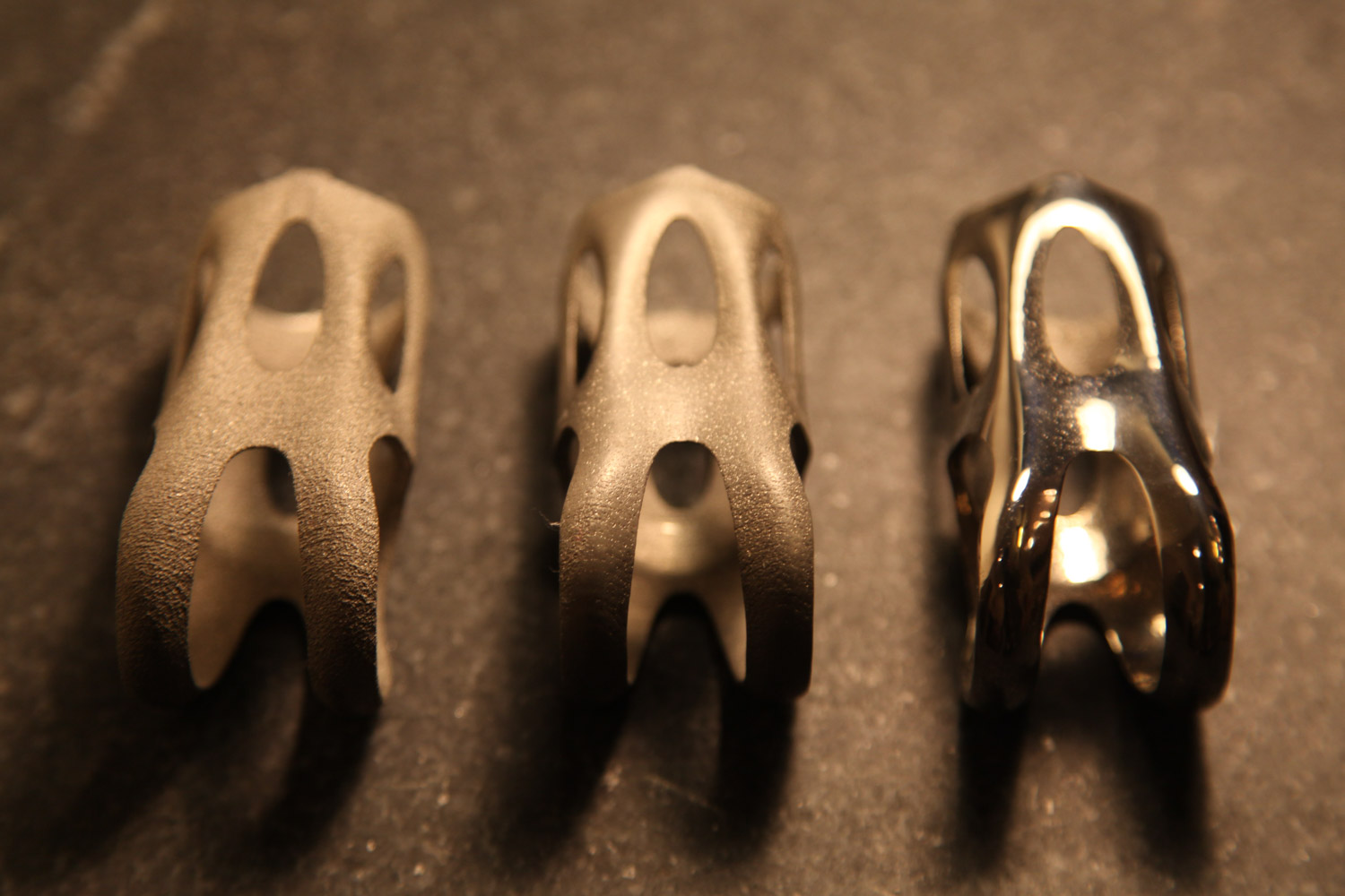
As you can probably see, the part on the left is unfinished. In the middle is an intermediate finish (~25µ" Ra), and on the right is a fine finish (~1.5µ" Ra). All three of these parts were printed on Addaero's Arcam A2X; their raw finish is about 600µ" Ra. 

Incidentally, I'll note that photographing the surface finishes on these parts has been remarkably challenging. I probably need a strobe or something, but hey - it's a labor of love.

I'll be writing up the results in the next few weeks. Stay tuned!

My writing in Metal Additive Manufacturing Magazine

Added on by Spencer Wright.

I'm extremely proud to say that my writing is featured in the current issue of Metal Additive Manufacturing Magazine. The article summarizes much of my work over the past two years, and includes many of my thoughts about how the industry can be better in the future. You can read the full article here.

Thanks so much to Nick Williams and the rest of the Metal AM for asking me to contribute!

DMLS vs EBM titanium parts

Added on by Spencer Wright.

Note: Below, I use the term "DMLS" to refer to laser metal powder bed fusion. Some will have issues with this usage; I encourage readers to ignore the (possibly trademarked) terms themselves and focus on the information contained within them.

Over the past few months I've spent a lot of time trying to determine whether DMLS or EBM would be a more suitable technology for the titanium bike parts I'm working on. Early on (in my collaborations with DRT and Layerwise) I focused on DMLS, and more recently I've worked with Addaero on EBM. These two technologies are in many ways complementary, and in truth I expect to work with both of them - but their design constraints and total manufacturing process chain are a bit different, and I wanted to spend some time understanding how that will affect the cost and quality of the parts I'm working on.

In the video below, I show some of the basic differences in surface quality and support structures. Of course there are many other factors that are worth exploration, starting with minimum feature size and built-in stress, probably; I'll get to those in future updates.

This video gives an overview of the differences between DMLS and EBM titanium parts. I show basic surface finish characteristics, support structures, and support removal.

Incidentally, I'm *really* interested to see the differences between DMLS and EBM in printing the lattice structures I've been working on. More soon :)

New EBM prints from Addaero

Added on by Spencer Wright.

Yesterday I went up to visit Rich, Dave, and Cesar at Addaero, and came home with a few new EBM prints. These are an iteration on the parts they printed me a few months back, and should be easier to post-process (and are lighter to boot :). 

I'm working on getting a better understanding of the differences in manufacturing process chain in DMLS and EBM (a life-cycle assessment of sorts), and one big difference ultimately will be surface finish treatments. As a result, I'll be sending these parts off to a few special places to get some very special surface treatments applied to them - and then will send them to EFBE for testing. It's likely that different treatments will result in different mechanical properties, and they'll definitely result in different cost structures as well. Stay tuned for updates :)

Notes on Magics

Added on by Spencer Wright.

This month I'm doing a deep evaluation of Materialise Magics 19 and SG+, and trying to understand both the major features of the software and the philosophical perspective that Materialise views additive manufacturing through. I'll post more thoughts on the overall process chain later, but for now I wanted to work through some of the observations I've had in my first encounters with Magics.

For background: The cost of this software is in the neighborhood of $20,000. It's generally NOT purchased by people who don't themselves own industrial (i.e. $250k+) 3D printers. But I feel very strongly that without some knowledge of how it works, independent designers will be doomed to creating inefficient, difficult to manufacture designs. So, I signed myself up for a 30 day demo and got working :)

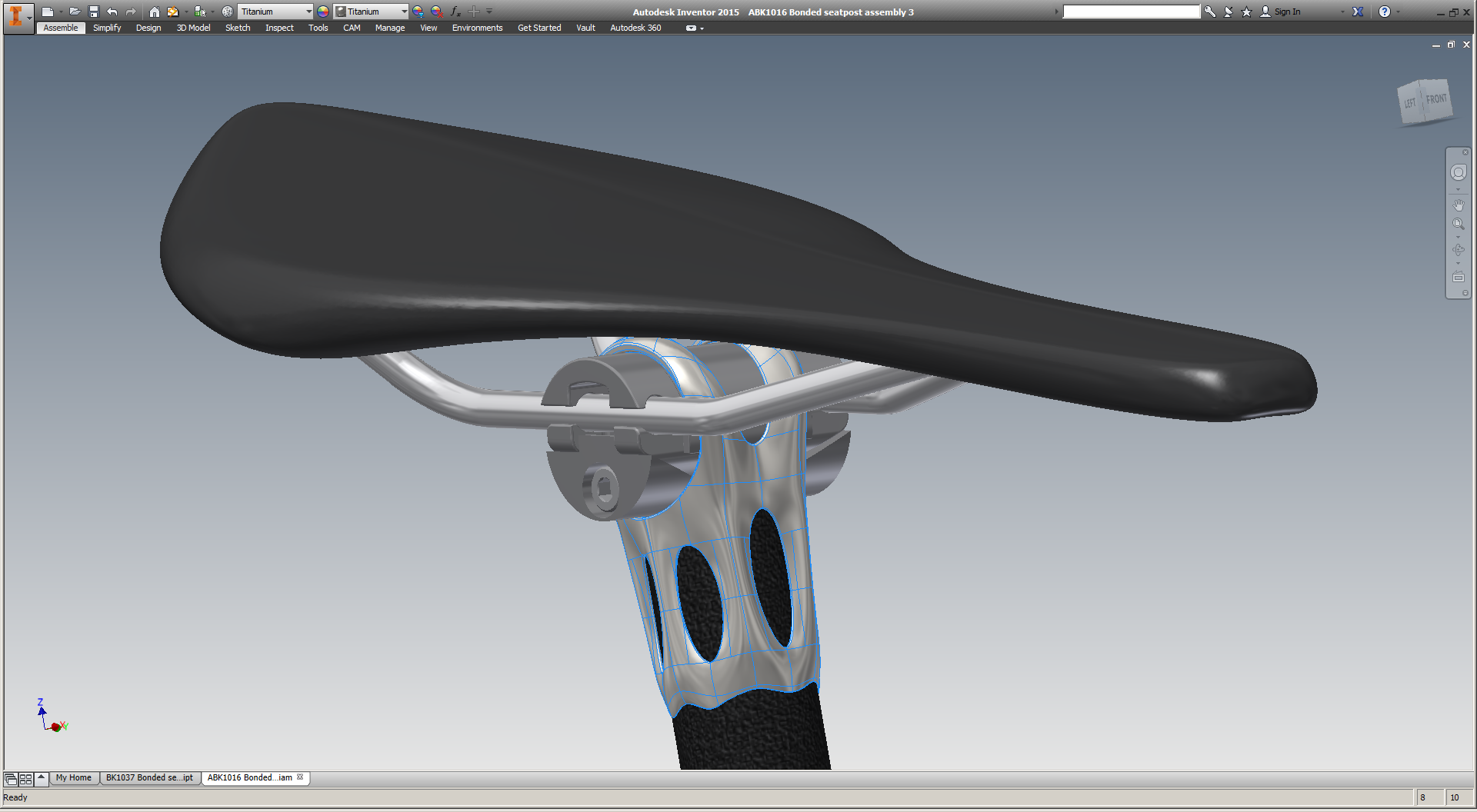
Note: Throughout this post, I'll be showing screenshots of my titanium seatpost part. I've already had one of these parts EBM printed by Addaero, and expect to have versions of it printed in both EBM and laser metal powder bed fusion (which I'll refer to as "DMLS" throughout this post) in the near future. In order to simplify the descriptions below, here's a key to the part's features:

My part's nomenclature.

Overview

I believe Magics to be a classic example of a piece of industrial software whose development has been driven by customers who are large, powerful, and often have divergent interests. 

In many ways its functionality probably benefits as a result. Materialise has close relationships with a number of industrial 3D printing machine manufacturers (notably Renishaw, SLM, and EOS, all of whom have agreements in place to allow Materialise access to their machines' build parameters, and develop build processors to work natively on those machines). They also collaborate closely with many of the large manufacturers (both OEMs and service bureaus) who build 3D print parts on the machines that Magics supports. Through these relationships (and through their own internal parts business), Materialise can get an up close view of what their biggest users need out of the software, and prioritize their efforts accordingly.

On the other hand, by relying heavily on key accounts to drive the product's development, Materialise gives up much in the way of product vision - accepting, instead, a steady stream of feature creep. Every additional feature (while I'm sure they're all valuable) makes the entire application more difficult and clunky to use, and it often feels like Materialise has given two different customers two distinct ways of doing the same thing - simply because each one demanded that the workflow fit their way of working. This kind of path is ubiquitous around the world of industrial software, and Materialise is, to be fair, ultimately at the whim of its (enormous) industrial stakeholders. But as someone coming in from the outside, the result feels schizophrenic.

The core issue is that independent designers like myself are seen as customers, while Magics' development is driven by client relationships. Again, this isn't Materialise's fault, and nor is it ipso facto bad. But I don't believe that the incentive structures that drive Magics' development are optimal for the industrialization of additive manufacturing, either. I'll explore this topic more in a later post; for now, just ponder this. In the meantime, here are my initial observations of how this big, important, and powerful piece of software works.

One important note: Materialise is a member of the 3MF consortium, which is working to create a file format which apparently contains "the complete model information" within "a single archive." My hope is that 3MF allows for more of the process chain to be accessible from a single interface, and that Materialise is a key part of that development. I'm looking forward to learning more about 3MF in the near future; stay tuned for more.

UI

Magics has two or three ways to do basically everything. At the top of the window is a drop down menu bar. It changes depending on context, but generally has a lot of functionality; in the default view, it has eleven menus - a mix of standard stuff (File/Edit etc) and context dependent stuff (Fixing/Scenes etc).

Directly below that is a tool bar, which mostly contains standard tools (undo/redo, Print 2D, Zoom/Pan/Rotate, etc). As far as I can tell, every command in the tool bar is also accessible via the menu bar AND via keystrokes & mouse gestures.

To the right of the tool bar is a series of tabs, which toggle the appearance of another tool bar below. These are a bit more context dependent, and as far as I can tell the correspond 1:1 with what's shown in the "Tools" drop down menu above. Most of these functions, though, *can't* be accessed by keystrokes or mouse gestures.

Overall, Magics' multiple, competing UIs are not unlike most of what's out there in industrial & B2B software today. Most companies (including Materialise) tend to bill this as a feature: the user can interact with the software in a wide variety of ways (keystrokes, mouse gestures, drop down menus, or toolbars), so almost anyone will be able to get comfortable with the interface quickly.

Personally, I prefer opinionated UIs in industrial/B2B software. The best one I'm aware of is McMaster-Carr's, which is built specifically for MRO professionals and makes everyone else adjust their mindset to that of someone looking for replacement parts. I'm not an MRO professional, but once you figure out how they work, the experience is wonderful. 

Magics doesn't act this way, though. The UI doesn't guide me at all; it simply offers a multitude of options, and lets me decide which one I prefer.

Orientation

Magics' "Orientation Optimizer" is very straightforward, and seems in some cases like it'd be useful. I used it only briefly, but to be honest I had already decided more or less the orientation I wanted the part to be printed in. As it happens, the Orientation Optimizer confirmed my plan, but I take that confirmation to be a bit of a false positive. As I discuss below (and have written about extensively in the past), setting an orientation angle really requires an understanding of the part's design intent and manufacturing life cycle, and Magics lacks these. As a result, it can only optimize for the factors that it understands: in this case, some combination of Z-height, XY projection, Support Surface, and Max XY Section. I chose the middle two of these, and Magics gave me exactly what I already knew I wanted.

The orientation that Magics suggested for my part

This tool is probably more useful in high mix environments (service bureaus), but most of the people in the industry I've spoken to say that when they use it, it's just as a starting point; the final orientation is almost always set by a human being.

Support generation

Generating support structures in Magics is really straightforward; it's possible (though almost definitely not ideal) to simply choose a machine, plop a part on the build plate, and hit "generate support." Magics has some understanding of the technology you're using (in my case, either EBM or DMLS), and it creates support geometries that are (reasonably well) tuned for the process. 

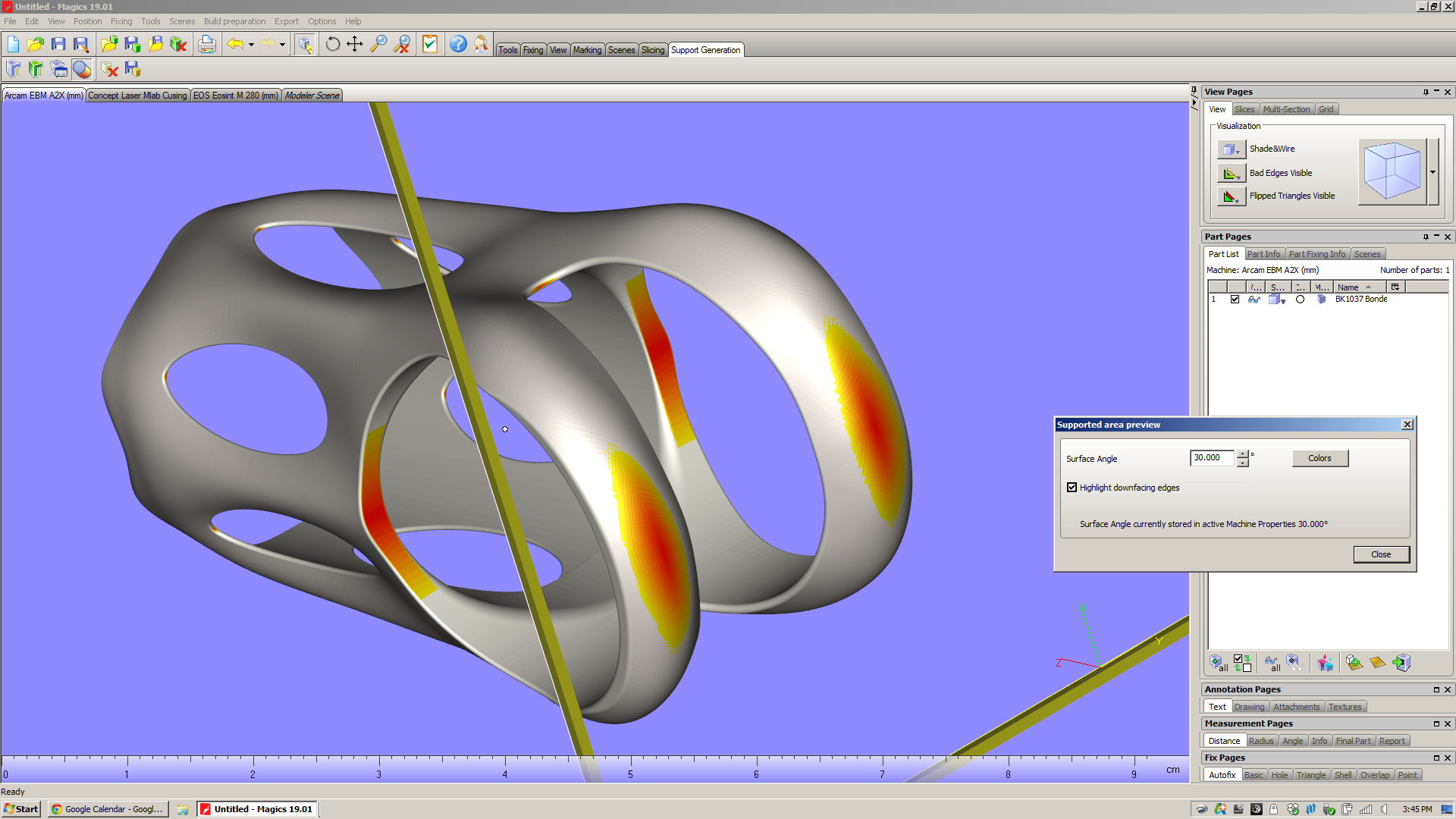
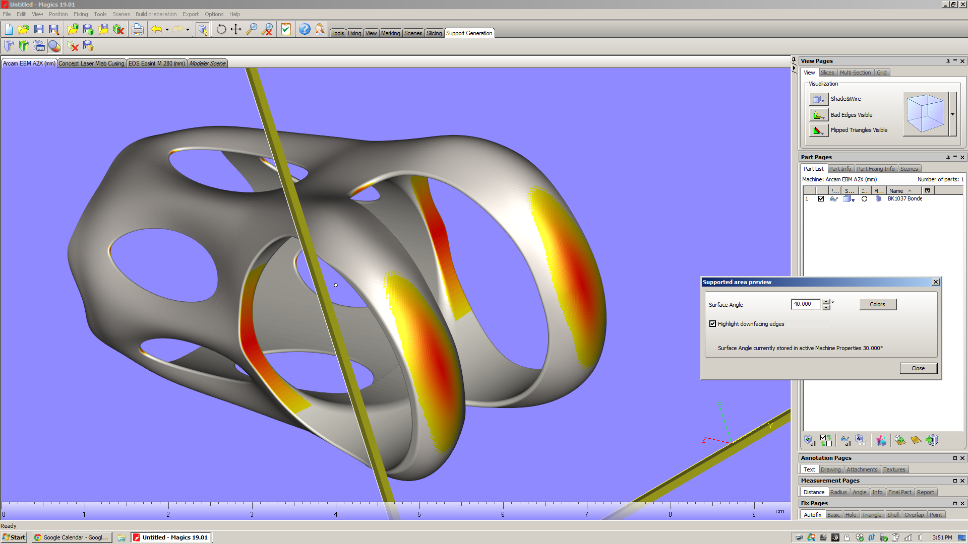
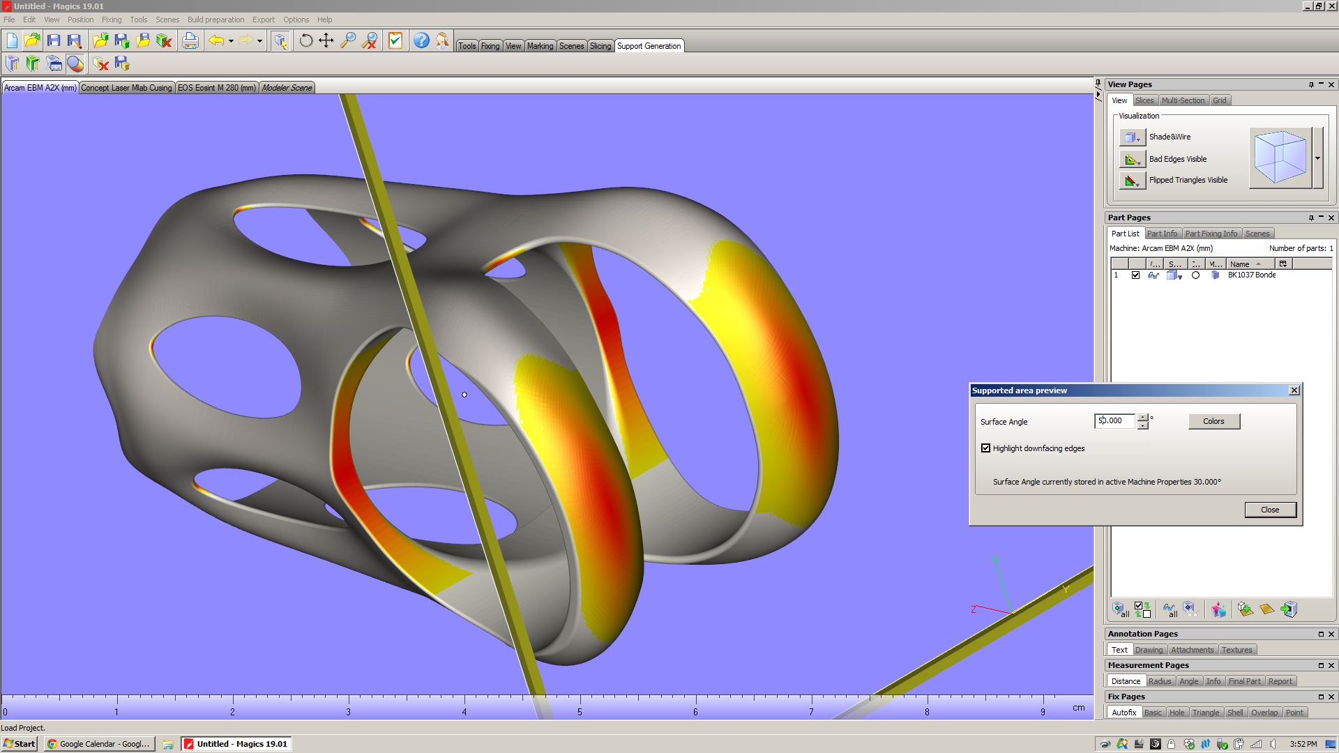
But before you even get that far, Magics has a nice feature that allows you to preview which surfaces will need to be supported - the "Supported area preview." Presumably this would be used while the operator is setting the part's orientation in the build chamber. It allows you to view downfacing edges as shaded, and it shades them on a color gradient depending on what you want to see. Here I'm looking at the underside of the part, and varying the angle that Magics highlights:

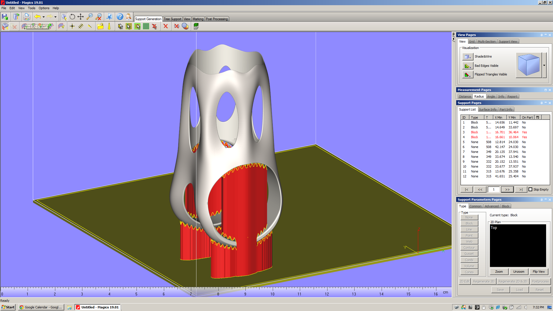
On my part and in this orientation, there are two large areas that need support structures (inside the saddle clamp cylinder, and from the shoulder straps down to the build platform). But if you look closely, you can see that there are also a series of tiny areas with downward facing surfaces:

  • At the v-necks, there's an surface below 30˚ whose area is .91mm^2. If you change the selection angle to 50˚, the area grows to 2.58mm^2.
  • At the window tips, there are surfaces with 30˚ whose areas are about (they vary slightly from window to window) .22mm^2. If you change the selection angle to 50˚, the areas grow to about .73mm^2.

For comparison, the cross sectional area of a "medium" grain of sand (as described by ISO 14688) is about .4mm^2. Which is to say that these are relatively small surfaces. My hope is that even though they face downwards, they won't require support structures at all.

When you enter the support generation module and hit "generate support," Magics simply looks at the faces that face downward, chooses a support type that's appropriate for the surface size & shape, and projects that support directly downward. Here are the automatically generated supports for both my part in EBM and DMLS:

Throughout Magics' UI, there are "tool pages" on the right of the window that offer a variety of context dependent functions. When you're in the support generation module, there's a section of "Support Pages" there that let you analyze and modify the support structures in your build. Looking at the support pages in the pictures above, you'll notice that I've got the "Support List" page open, and that there are 12 supports listed in that view. For each of these, a variety of data is displayed: ID; type of support; some basic geometrical data, and an "On Part" column. You'll also notice that the supports that are "On Part" are keyed red in the list. This is a very useful piece of information: those supports, when they were projected downwards, ended up falling onto the part itself. The result is that when the part is printed, those supports will tend to be more difficult to remove. In the case of the MLab build above, supports 3 and 4 run the full inner diameter of the saddle clamp cylinder. In the Arcam A2X build, supports 3 and 4 are in the same situation - but a whole series of point supports (7-12) are also partly trapped in the part's windows.

In my experience, this is *not* desirable. Especially with EBM, supports that fall onto the part itself are a real pain in the ass to chip out (for a bit of context, see the photos I took of the first parts I had EBM printed). In addition, they tend to make the surface they're hitting rough, and as a result the part often requires more post processing.

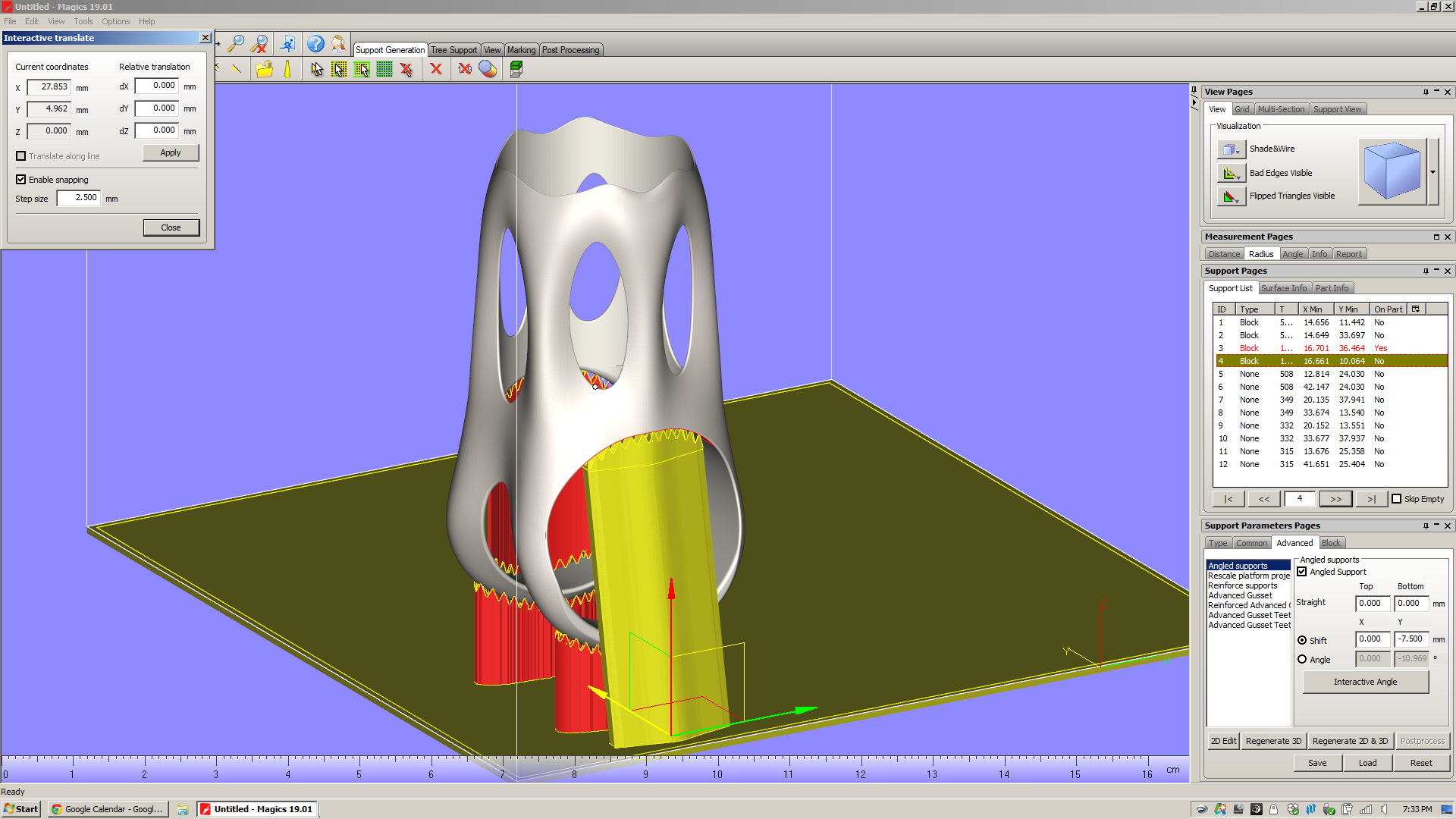
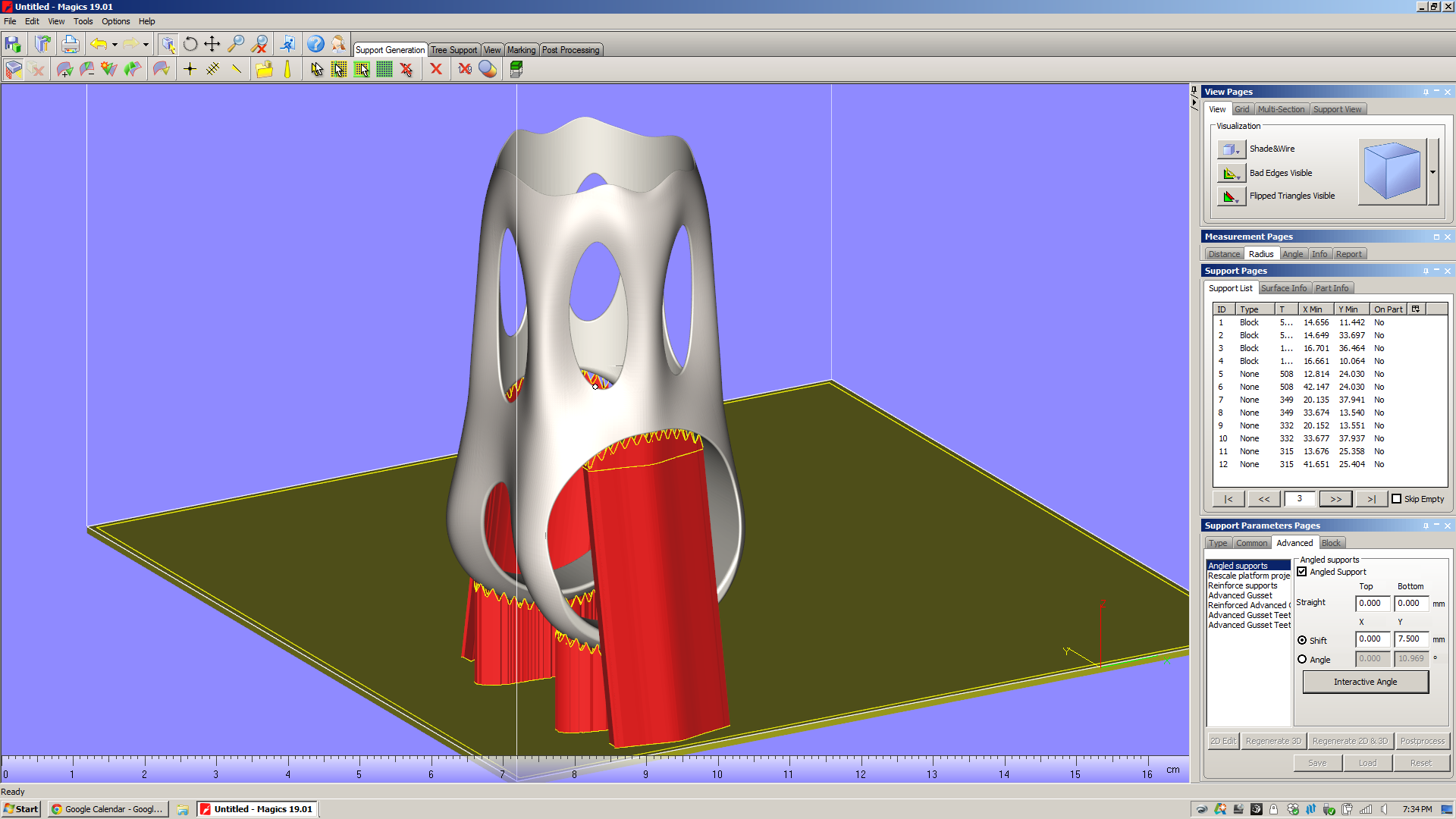
In order to avoid this, I need to modify the support parameters. By going into the "Advanced" section of the Support Parameters Pages and checking off "Angled supports," I can pull the two big Block supports (ID 3 and 4) away from the part:

(I'm working on similar edits to the EBM build, but want to get a little clarification from Arcam on those point supports first.)

I can do a variety of other things to these supports, including "Rescale platform projection," which essentially flares the support in/out as it goes down to the platform. There are also a slew of parameters (hatching, hatching teeth, teeth synchronization, perforations, etc) which seem mostly designed to make the supports easier to remove from the part. All of these can be preset in the Machine Properties screen (which, frustratingly, isn't accessible when you're in Support Generation mode) or adjusted on a support-by-support basis from the "advanced" tool pages.

To be sure, I'm only scratching the surface on Magics' support generation features here. Magics will let you play with a *ton* of support parameters. I get the impression that there's a lot of nuance here, and that there are many parameters that you'd only play with in edge case builds. Regardless, the number of possibilities generated by varying just a few of the options is staggering; in order to know how they affect part quality, you'd need to run thousands upon thousands of test builds.

Eventually, it's very likely that Magics (or whatever replaces it) will have thermal & residual stress simulations built right into the software. Today, however, machine operators have remarkably little info about the finished part before they actually print it. Except...

Build time estimation

This is a key part of the additive design-for-manufacturing process. Knowing how long a part will take to print is a *huge* factor in what it costs, and is critical in comparing two build configurations for the same part.

Magics has a build time estimator, but it's not plug-and-play. Instead of shipping pre-loaded with estimates of how long a given machine will take to build a part, Magics requires the user to run "Learning Platforms" - and you need to own your own machine to do that. And, of course, I don't own a metal powder bed fusion machine.

I was *really* excited to get a build time estimation, but no dice.

The reason for this is that in order to estimate build time, you need to know how both the slicer and scanning strategy work - as well as mechanical factors like scanning speed and recoating time. And while certain machine manufacturers (see below) share this information with Materialise, for many it simply isn't worth it. They see those process parameters as valuable, and don't see the benefit of sharing that data with a third party software developer. Moreover, most of them can provide very accurate build time estimations in their own software, and the manufacturing engineers that use the machines take it as given that they need to use that at some point in the process anyway.

This strikes me as a big failing. Magics needs a way of sharing data about their builds: a public repository of machine parameters and build times. Without that - or without, on the other hand, convincing the machine manufacturers to share that data themselves - Magics is left with a huge disconnect between the build setup and the end product. This undercuts Magics' claim to be "The link between your CAD file and the printed part." If it lacks basic data on build speed for the most common machines in the industry, what exactly is it linking to?

So: As of the time I'm writing this, I've got emails out to a handful of the biggest metal powder bed fusion machine manufacturers in the industry, asking for Magics learning platforms. If anyone out there can share that data with me, please send me a note!

Build Processors

My demo doesn't include these, but they're worth touching on. For a few big machine manufacturers (Renishaw, SLM, and EOS), Materialise has developed build processors that are tuned to those machines' capabilities and specifications. Presumably, these companies provide Materialise with in-depth data about how their machines work, some of which is either patented or proprietary. Materialise then builds software modules that, through a few intermediate steps (the most notable of which are slicing and subdividing/hatching), produce a job file that can go directly to a machine.

Materialise bills the build processors as reducing complexity in the manufacturing life cycle, and allowing both Materialise and the machine manufacturers "to focus on their core competencies." Having not played with them myself, I can't really comment. I hope to learn more soon.
A few things Magics *can't* do

To reiterate: It's my impression that Materialise built Magics to fill a really big hole in the existing work chain, and the bottom line is that that work chain is something that no single party (let alone Materialise) created. It's also, in my opinion, *not* the right work chain for the future of additive manufacturing, and Magics' role in it highlights a lot of the problems in the industry today. Here are a few things that I noticed that Magics can't, for various obscure and not-so-obscure reasons (many of which are decidedly *not* Materialise's fault), do.

Understand the underlying design

This is something I've touched on in previous posts, but it struck me again when I was in the "supported area preview" screen. It's *very* likely that I could, with a relatively small amount of work, edit the underlying geometry in order to reduce the number of supports needed significantly. But I'm not aware of a way of showing downfacing regions in solid modeling software (Solidworks/Inventor, etc), and it's rather cumbersome to bounce back and forth between Magics and Inventor to try to optimize the design for additive. 

All across the industry today, I hear people talk about design software that understands the intent of the designer, and responds to accommodate it. This may be feasible in the near future, but the bottom line is that Magics (as it stands now) is *not* part of that process chain. Once a designer transitions from parametric modeling to surface tessellations, all of the geometry data is lost. If manufacturability feedback (like the supported area preview screen) is provided in software that reads surface tessellations (as Magics does), then going back to edit the underlying parametric model is *always* going to be cumbersome - and necessary.

Understand/display surface quality issues due to orientation

In all additive processes that I'm aware of, surface finish will vary significantly depending on the orientation of a surface relative to the build direction. Given the layer thickness of the printed part, this is relatively straightforward to simulate - not to a high degree of precision, but with a good amount of accuracy, at least. Magics doesn't do this, and it leaves me feeling like I'm missing a key piece of information about the printed part. Sure, I can imagine what the part will look like if I just think about it for a minute, but it does strike me that having some indication of areas with high stepover (which will occur wherever a surface is oriented close to the XY plane) would be really helpful - and not particularly hard to implement (caveat: everything I said above about feature creep, etc).

Understand the place of additive in the process chain

This may seem like I'm splitting hairs, but I think it's worth reiterating: Magics bills itself as "The link between your CAD file and the printed part." It is NOT concerned with the end product, which in almost all cases will have additional (subtractive) processes performed on it.

Why does this matter? When I had this part EBM printed recently, both the saddle clamp cylinder and the seatpost cylinder came out undersized. I know now that one of two things needs to happen there: either I need to compensate for the printing process in the underlying model (by making the designed dimension larger than I actually want it to be), or I need to remove material from the as-printed part (by machining, grinding, or similar).

Magics doesn't know any of this. If it did, it might be able to give me intelligent advice on what surfaces to take extra care with - and which I should ignore, as they'll be machined away in the end regardless.

In the end, Magics is a piece of CAM software - but it only deals with one step in the production chain. Changing this is a monstrous, complex task, but it's one whose impact will be hugely positive.

So

Magics is pretty cool - it does a *ton* of really useful stuff. You'll note, also, that I'm basically not interested at all in its "fix" feature, which (I'm told) is used a lot with models that come out of Rhino.

But it's also representative of a lot of what's going on in industrial additive manufacturing today. This isn't Materialise's fault; it's just the way things evolved, and is the result of (I'm sure) a lot of collaboration, competition, and plain old hustling (all of which I fully support) in the industry over the past few decades.

Regardless, Magics is a place where you can see a lot of the implicit assumptions that industrial additive manufacturing has been built upon. More on this soon.
This week: Materialise Magics 19 and SG+

Added on by Spencer Wright.

Just a little teaser:

This week, in addition to the networking I'm doing (remember: I'm a free agent now, and directing my efforts toward finding the best path for myself in metal additive manufacturing), I'll be diving deep into Materialise Magics 19, the industry standard software for metal 3D printing build processing. I'm excited to learn more about its capabilities, and will share more later this week. I'll be spending most of my time working on orientations & support structures schemes for my titanium seatpost head, seen here in Magics' simulation of an EOS M280:

Magics bills itself as "The link between your CAD file and the printed part." It's used by OEMs and service bureaus alike to prepare design files to be printed - often times on the very machines that I've been building parts on (one, two) over the past year. In most cases, Magics imports an STL file. It then can be used for three big chunks of work:

  1. Fixing. In many cases the files that you import are broken in some way (edges not connected; faces oriented in the wrong direction), and can't be printed as is. Magics has a suite of tools that analyze and solve these problems.
  2. Editing. There are a variety of reasons why you'd want to edit a design before printing it, but probably the most common is that it won't fit in the build chamber of the machine it's being printed on. Magics offers tools that cut, hollow, thicken, perforate, extrude, label, boolean, and support parts and their features.
  3. Build prep. This is the part that I'm most interested in, as it directly affect the workflow that I've beed dealing with on my titanium parts. Here, the user selects the machine that the parts will be printed on. Then the parts are oriented physically within the build chamber, and an analysis is run to confirm that there are no part collisions that will affect the build.
Lastly - and of particular interest - is the SG+ module for support generation in metals. This would fall somewhere between (and across) numbers 3 and 4 above, and involves creating solid and mesh support structures that anchor the part to the build plate and provide thermal sinks to ensure a successful build. The SG+ module is a critical part of the metal 3D printing process chain today. It's used extensively across the industry, and engineers who are skilled at support generation are highly prized.

This week I'll be exploring these features (especially build prep and SG+) extensively; stay tuned for updates.

Some quick modeling

Added on by Spencer Wright.

It's been a little while since I've played with this design, and I enjoyed getting back in to it. To be honest I'd like to spend a few days working on the model (I'd probably tear it down completely and start from scratch) but for now this is looking pretty nice.

Incidentally, T-splines continue to be *really* weird - and super cool. I really wish I had a more powerful computer; I suspect that would improve the experience significantly.

Planning for post processing

Added on by Spencer Wright.

The other day I got an email update from Rob Oliver, a machinist in Brooklyn who's helping me post process the EBM printed titanium parts that I got from Addaero recently. There's still a bunch of work to be done, but I wanted to write a bit about how we're thinking of the manufacturing plan - and the constraints that we're facing in the process.

While electron beam melting tends to produce much lower internal stress than laser powder bed fusion does, it's still a decidedly near net shape process. In further iterations I hope to get the as-printed part much closer to the final dimensions, but at this stage the parts I have deviate significantly from the intended tolerances. Specifically, most outer dimensions seem to have grown, most inner dimensions seem to have shrunk, and there are a number of locations where support structures have left unacceptable surface finishes.

My main focus right now is getting both inner diameters to within .006" of their designed size. It's difficult to get a reliable measurement of where they are now (due mostly to surface finish, and the presence of leftover support material), but they both appear to be about .040" undersized. In addition, I suspect that the shorter cylinder is slighly ovalized - though not to the extent that it'll be an issue in the end.

Although there are other conceivable options, the most obvious way to get the IDs within tolerance is milling. By using either a CNC toolpath on an end mill, or a boring bar on a conventional mill, it should be very easy to get well within .006" of nominal dimensions on both areas of the part. However, the issue of fixturing is nontrivial. I designed this part with T-splines, and its outer surfaces aren't orthogonal at all. As a result, we'll need custom tooling to hold the parts in a milling vise.

As an aside: Anyone who says that additive manufacturing eliminates the need for custom tooling has no idea what they're talking about. 

In order to securely fixture this part, Rob is machining its negative into a set of aluminum blocks, which can then be clamped securely into a milling machine vise. This technique (which I'll refer to here as "soft jaws," although technically what we're making is more of a coped fixturing block) is used extensively in subtractive manufacturing to hold irregularly shaped parts. 

The process of making soft jaws is relatively straightforward, but designing them for this part is somewhat complicated by the dimensional variation that EBM produces. Put simply, feature sizes in EBM parts tend to deviate from the design in the X and Y axes, but stay relatively true to size in the Z. That's because the Z axis is at least partly controlled by the Z stage drive system; the powder bed is lowered a predictable amount with each new layer, keeping features in the Z close to their designed dimensions. But in the X and Y, deviations in feature size are partly driven by the electron beam diameter, and partly driven by the distance that the feature is from the center of the build platform. 

As a result, my part has grown anisotropically, and Rob will need (to some extent or another; soft jaws tend to be somewhat forgiving) to compensate for the as-printed dimensions differently in the XY plane than he does in the Z.

In the end, though, the most practical way of determining the final dimensions of the soft jaws is to make a set, test them on the as-printed part, and iterate as necessary. It's conceivable that the first try will work, and it's also possible that if we make the negative a bit too big in all directions, we could use a piece of soft material (for instance, blue tape) to take up the gap.

It's also worth noting that there's an alternative path that I decided *not* to take. A common way to make parts - both with additive manufacturing and conventional - is to design fixturing features into an intermediate stage of the part. These can then be used to hold the part while secondary operations are performed; they can then be removed in a subsequent step. I considered this option, but find it undesirable for the simple reason that it would likely result in more post processing steps. Worse yet, it would probably require the surface of the part to be blended where the fixturing element had been removed, which would be either labor intensive, or unattractive, or both.

Regardless, we should have the first iteration of our soft jaws machined shortly. Expect updates!

First EBM prints

Added on by Spencer Wright.

A few weeks ago I visited Addaero Manufacturing, one of the very few EBM (electron beam melting) service providers in the US. After my recent trials (and successes) with laser powder bed fusion, I wanted to try building parts with EBM. EBM is used extensively by aerospace and medical OEMs, but its penetration into the job shop world is way behind laser. Addaero, whose founders (Rich Merlino and Dave Hill) both worked at Pratt & Whitney before striking out on their own, is located just a few hours from New York City, and they were gracious enough to build two parts for me to evaluate the process.

I'll be writing up a longer post on the unique design considerations that EBM poses, but for now I wanted to share the pictures I took while there:

At this point, the parts Addaero made for me still need post processing before they can be assembled and tested. I'll be working on that over the coming weeks, and will update soon on my progress.

Things that are on my plate right now

Added on by Spencer Wright.

Mostly for my own benefit & the sake of catharsis, here are the things that are consuming my attention over the past & for the next few months:

  • Planning my own wedding in October.
  • Having fun this summer.
  • Getting more exercise.
  • Writing a long blog post on the seatmast topper that I had printed (DMLS) by Layerwise, and then tested by EFBe
  • Writing a long blog post on the seatpost that I had printed (EBM) by Addaero.
  • Digging more into McMaster-Carr's iOS app, and comparing it to Amazon's recently rebranded Business offering.
  • Planning a sourcing trip to Shenzhen, where Zach and I will investigate a significant redesign of The Public Radio's speaker & mechanical assembly.
  • Getting more hands-on experience with metal powder bed fusion machines. Because there are none in the New York metropolitan area, this inevitably means traveling for a few days to somewhere where I have a friend in the industry.
  • Doing a deeper dive into the variety of design tools that are cropping up for additive manufacturing. This includes getting better at T-splines (Autodesk Inventor), working with topology optimization software (SolidThinking Inspire; Frustum Cloudmesh), and doing some experimenting with lattice structure generation (with nTopology).
  • Doing a deeper dive into build preparation software, namely Materialise Magics.
  • Building myself a real desk, preferably with a proper toolchest integrated into it. I also want 2x24" displays, a proper Windows computer for 3D design, a new Mac for daily use, and a place for both a Wilton "bullet" vise and my 12"x18" granite surface plate.
  • Writing a presentation on metal 3D printing that covers both my experiences over the past two years (a case study), and my broader observations on the industry. 
  • Getting said presentation accepted to an industry conference (likely either AMUG, RAPID, or Inside 3D Printing).

There are a few more longer-term things, but this is a pretty good list for now. 

Measuring process signatures is hard

Added on by Spencer Wright.

From a NIST report titled Measurement Science Needs for Real-time Control of Additive Manufacturing Powder Bed Fusion Processes:

Finally, metallic debris from the [heat affected zone] can coat a window or viewport used in an AM imaging system, and disturb temperature measurements by changing the radiation transmission through the window. This is particularly troublesome in electron-beam melting (EBM) systems, and prompted Dinwiddie et al. to create a system to continuously roll new kapton film over the viewport in order to provide new, unsullied transmission.
This is a very important and totally nontrivial challenge. Measuring process signatures (which this report defines as "the dynamic characteristics of the powder heating, melting, and solidification processes as they occur during the build") is key to the industrialization of additive manufacturing. If the systems we have for measuring those factors are unreliable, machine manufacturers need to develop improvements for them ASAP.
The six questions I think about when I think about industrial additive manufacturing

Added on by Spencer Wright.

Prompted by an impromptu back and forth with Jordan, I was compelled to write down the things I spend so much of my time thinking about. Some of these I have a better grasp on than others, but they're all problems that I'm excited to see developments on - and work on myself.

1. What are the process parameters that affect finished part shape?

I'm in the middle of a NIST report that goes through many of these. The sad thing is that knowing what the parameters are is only half of the battle; then, you need to control those parameters on-the-fly (which is not something that all machine manufacturers currently allow).

2. What are the most reliable and effective methods of measuring, recording, and processing those parameters?

Industrial additive manufacturing machines tend to be harsh environments for sensors and sensor hardware. Once we know what parameters to measure, we'll need to build measurement systems that are robust, accurate, and reliable.

3. Given two identical finished parts with two different production process chains (additive, subtractive, etc.), how can one determine which process chain will be more expensive to complete?

This is hard. I believe that it'll be easier to automate process chain comparison than it will be to automate process chain creation; in other words, coming up with a list of steps to manufacture a part will remain hands-on, but assessing the cost difference (time/money/energy) between two process chains will be increasingly automated. Regardless, these are big problems.

4. Given two different designs, each of which has the same end functionality, how can one determine which design will be more expensive to build?

This feeds into question 3. In many cases today, design decisions are made based on a hunch. If it were easier to estimate the production cost for parts with complex production process chains, designers would be able to make more informed decisions.

5. Given the same input design and two different additive build orientations, how can one determine which build orientation will produce the most high fidelity net near shape, at the lowest cost?

Also feeds into question 3. Manufacturing engineers need to pick a build orientation quickly and be guaranteed high fidelity end parts; today, those decisions are made mostly by gut. Bonus points if this data is also made available to designers, so that they can make even more informed design decisions.

6. Given the same input design and build orientation, how can one determine which support structure design will produce the most high fidelity net near shape?

Given the early effort that startups (namely 3DSIM) are putting into this question, it stands to reason that it's an easier one to solve than question 5. It's also possible that they think it'll be easier to commercialize support structure optimization software in the near future. Either way, I see this as just part of a bigger need that 5 and 6 are pointing at together: additive manufacturing engineers need better tools to set up and process builds.


These issues outline the biggest roadblocks that I've experienced on my path to commercially viable additively manufactured parts. If you have different experiences, or know of developments on what I've described here, I'd love to hear from you.