This month I'm doing a deep evaluation of Materialise Magics 19 and SG+, and trying to understand both the major features of the software and the philosophical perspective that Materialise views additive manufacturing through. I'll post more thoughts on the overall process chain later, but for now I wanted to work through some of the observations I've had in my first encounters with Magics.
For background: The cost of this software is in the neighborhood of $20,000. It's generally NOT purchased by people who don't themselves own industrial (i.e. $250k+) 3D printers. But I feel very strongly that without some knowledge of how it works, independent designers will be doomed to creating inefficient, difficult to manufacture designs. So, I signed myself up for a 30 day demo and got working :)
Note: Throughout this post, I'll be showing screenshots of my titanium seatpost part. I've already had one of these parts EBM printed by Addaero, and expect to have versions of it printed in both EBM and laser metal powder bed fusion (which I'll refer to as "DMLS" throughout this post) in the near future. In order to simplify the descriptions below, here's a key to the part's features:
Overview
I believe Magics to be a classic example of a piece of industrial software whose development has been driven by customers who are large, powerful, and often have divergent interests.
In many ways its functionality probably benefits as a result. Materialise has close relationships with a number of industrial 3D printing machine manufacturers (notably Renishaw, SLM, and EOS, all of whom have agreements in place to allow Materialise access to their machines' build parameters, and develop build processors to work natively on those machines). They also collaborate closely with many of the large manufacturers (both OEMs and service bureaus) who build 3D print parts on the machines that Magics supports. Through these relationships (and through their own internal parts business), Materialise can get an up close view of what their biggest users need out of the software, and prioritize their efforts accordingly.
On the other hand, by relying heavily on key accounts to drive the product's development, Materialise gives up much in the way of product vision - accepting, instead, a steady stream of feature creep. Every additional feature (while I'm sure they're all valuable) makes the entire application more difficult and clunky to use, and it often feels like Materialise has given two different customers two distinct ways of doing the same thing - simply because each one demanded that the workflow fit their way of working. This kind of path is ubiquitous around the world of industrial software, and Materialise is, to be fair, ultimately at the whim of its (enormous) industrial stakeholders. But as someone coming in from the outside, the result feels schizophrenic.
The core issue is that independent designers like myself are seen as customers, while Magics' development is driven by client relationships. Again, this isn't Materialise's fault, and nor is it ipso facto bad. But I don't believe that the incentive structures that drive Magics' development are optimal for the industrialization of additive manufacturing, either. I'll explore this topic more in a later post; for now, just ponder this. In the meantime, here are my initial observations of how this big, important, and powerful piece of software works.
One important note: Materialise is a member of the 3MF consortium, which is working to create a file format which apparently contains "the complete model information" within "a single archive." My hope is that 3MF allows for more of the process chain to be accessible from a single interface, and that Materialise is a key part of that development. I'm looking forward to learning more about 3MF in the near future; stay tuned for more.
UI
Magics has two or three ways to do basically everything. At the top of the window is a drop down menu bar. It changes depending on context, but generally has a lot of functionality; in the default view, it has eleven menus - a mix of standard stuff (File/Edit etc) and context dependent stuff (Fixing/Scenes etc).
Directly below that is a tool bar, which mostly contains standard tools (undo/redo, Print 2D, Zoom/Pan/Rotate, etc). As far as I can tell, every command in the tool bar is also accessible via the menu bar AND via keystrokes & mouse gestures.
To the right of the tool bar is a series of tabs, which toggle the appearance of another tool bar below. These are a bit more context dependent, and as far as I can tell the correspond 1:1 with what's shown in the "Tools" drop down menu above. Most of these functions, though, *can't* be accessed by keystrokes or mouse gestures.
Overall, Magics' multiple, competing UIs are not unlike most of what's out there in industrial & B2B software today. Most companies (including Materialise) tend to bill this as a feature: the user can interact with the software in a wide variety of ways (keystrokes, mouse gestures, drop down menus, or toolbars), so almost anyone will be able to get comfortable with the interface quickly.
Personally, I prefer opinionated UIs in industrial/B2B software. The best one I'm aware of is McMaster-Carr's, which is built specifically for MRO professionals and makes everyone else adjust their mindset to that of someone looking for replacement parts. I'm not an MRO professional, but once you figure out how they work, the experience is wonderful.
Magics doesn't act this way, though. The UI doesn't guide me at all; it simply offers a multitude of options, and lets me decide which one I prefer.
Orientation
Magics' "Orientation Optimizer" is very straightforward, and seems in some cases like it'd be useful. I used it only briefly, but to be honest I had already decided more or less the orientation I wanted the part to be printed in. As it happens, the Orientation Optimizer confirmed my plan, but I take that confirmation to be a bit of a false positive. As I discuss below (and have written about extensively in the past), setting an orientation angle really requires an understanding of the part's design intent and manufacturing life cycle, and Magics lacks these. As a result, it can only optimize for the factors that it understands: in this case, some combination of Z-height, XY projection, Support Surface, and Max XY Section. I chose the middle two of these, and Magics gave me exactly what I already knew I wanted.
This tool is probably more useful in high mix environments (service bureaus), but most of the people in the industry I've spoken to say that when they use it, it's just as a starting point; the final orientation is almost always set by a human being.
Support generation
Generating support structures in Magics is really straightforward; it's possible (though almost definitely not ideal) to simply choose a machine, plop a part on the build plate, and hit "generate support." Magics has some understanding of the technology you're using (in my case, either EBM or DMLS), and it creates support geometries that are (reasonably well) tuned for the process.
But before you even get that far, Magics has a nice feature that allows you to preview which surfaces will need to be supported - the "Supported area preview." Presumably this would be used while the operator is setting the part's orientation in the build chamber. It allows you to view downfacing edges as shaded, and it shades them on a color gradient depending on what you want to see. Here I'm looking at the underside of the part, and varying the angle that Magics highlights:
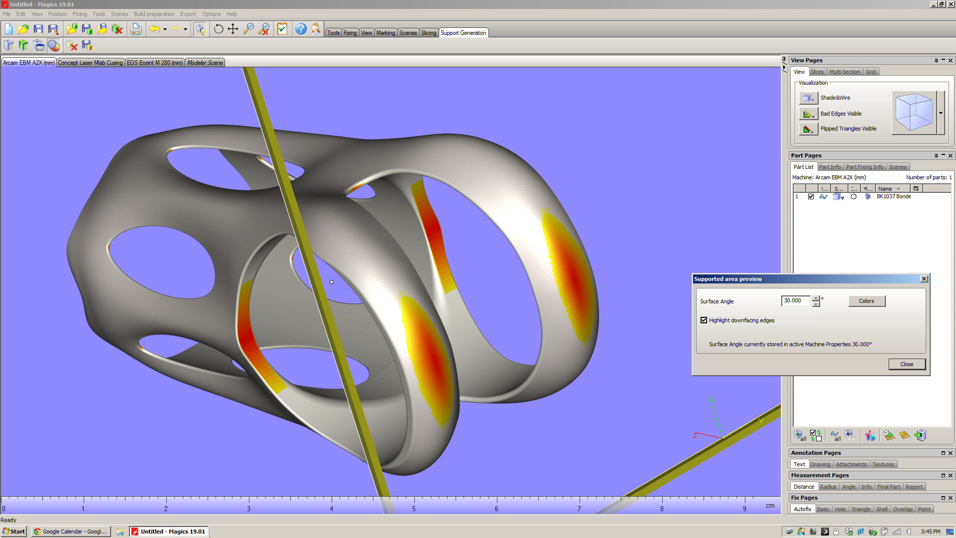
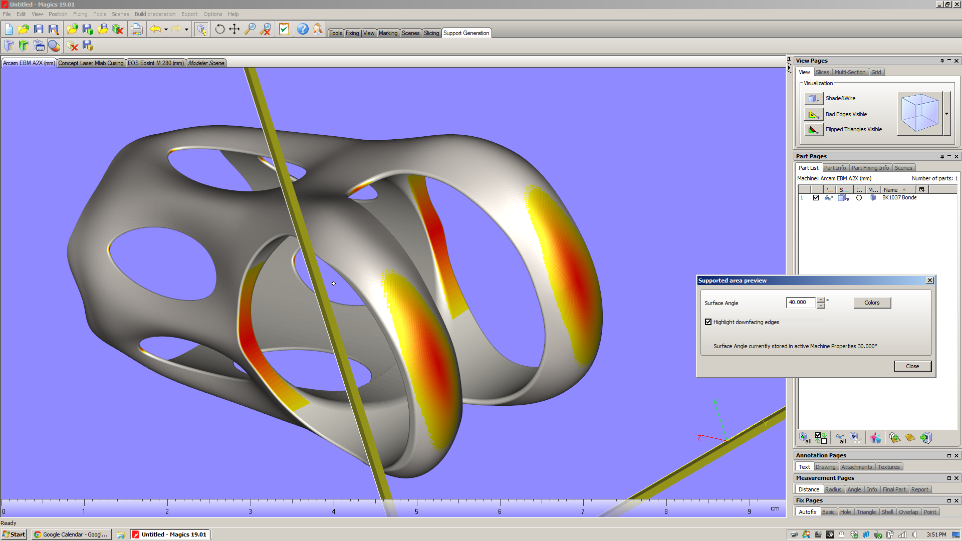
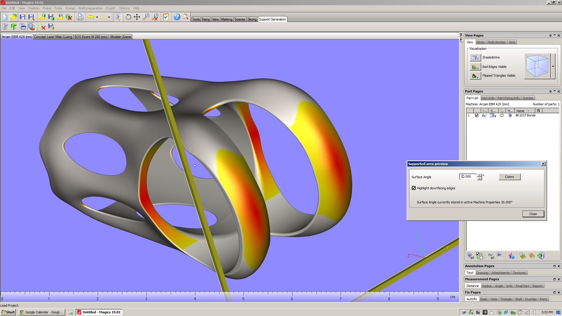
On my part and in this orientation, there are two large areas that need support structures (inside the saddle clamp cylinder, and from the shoulder straps down to the build platform). But if you look closely, you can see that there are also a series of tiny areas with downward facing surfaces:
- At the v-necks, there's an surface below 30˚ whose area is .91mm^2. If you change the selection angle to 50˚, the area grows to 2.58mm^2.
- At the window tips, there are surfaces with 30˚ whose areas are about (they vary slightly from window to window) .22mm^2. If you change the selection angle to 50˚, the areas grow to about .73mm^2.
For comparison, the cross sectional area of a "medium" grain of sand (as described by ISO 14688) is about .4mm^2. Which is to say that these are relatively small surfaces. My hope is that even though they face downwards, they won't require support structures at all.
When you enter the support generation module and hit "generate support," Magics simply looks at the faces that face downward, chooses a support type that's appropriate for the surface size & shape, and projects that support directly downward. Here are the automatically generated supports for both my part in EBM and DMLS:


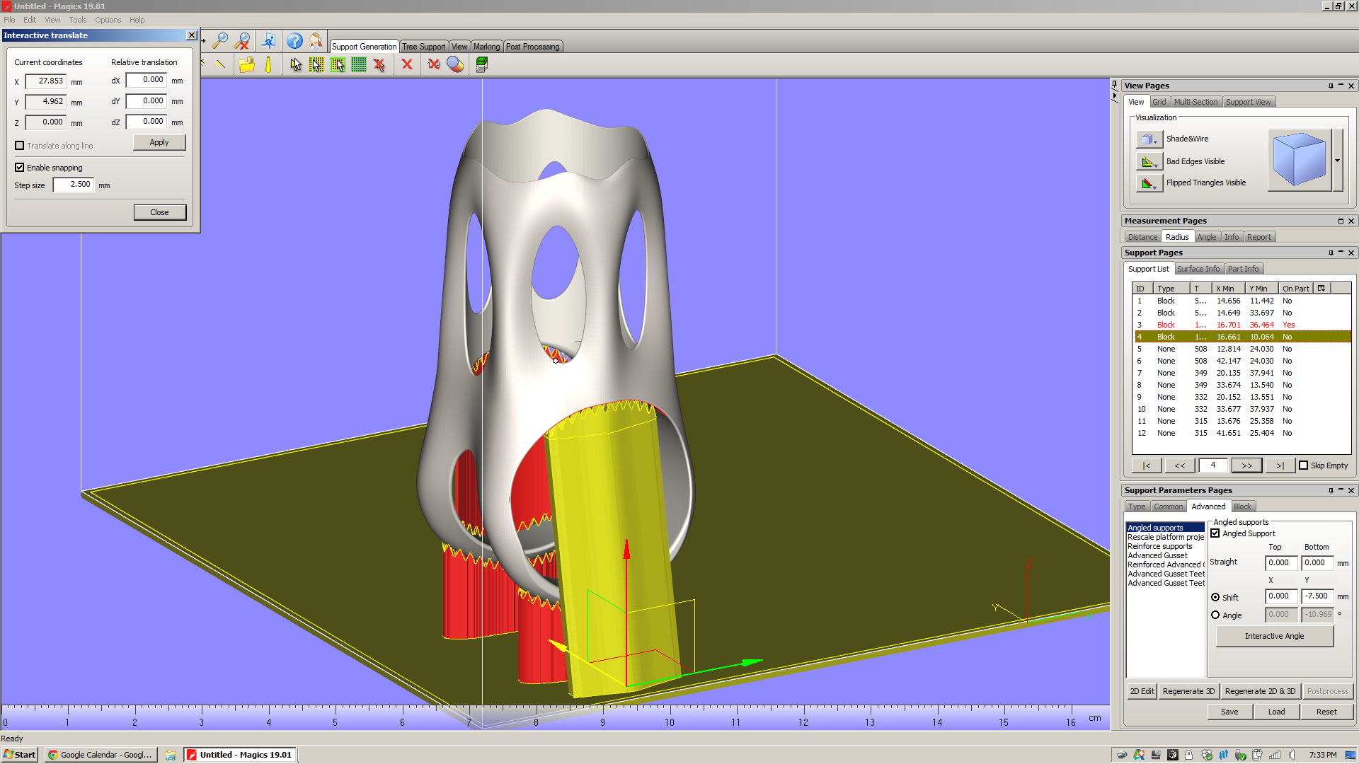
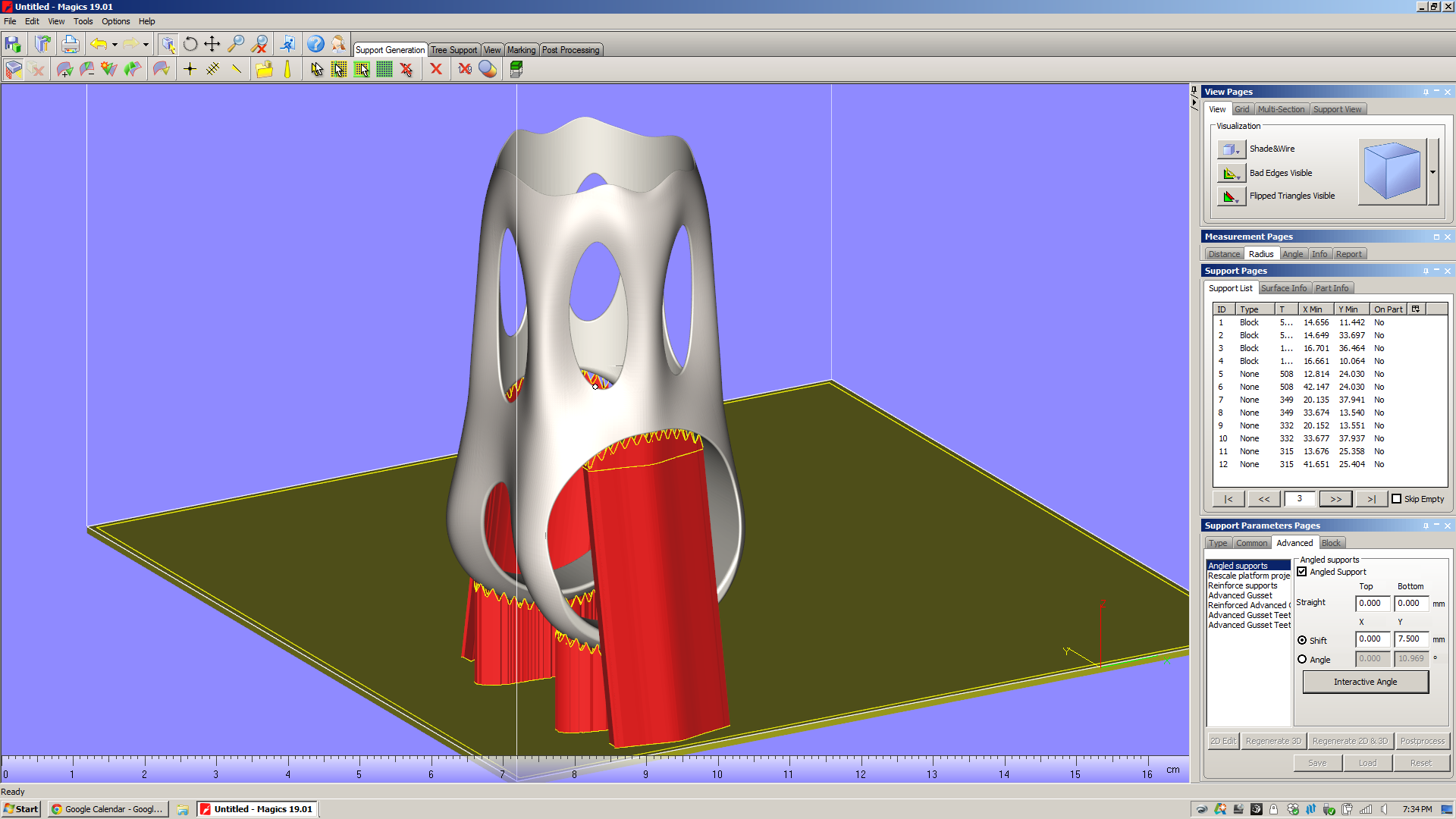
Throughout Magics' UI, there are "tool pages" on the right of the window that offer a variety of context dependent functions. When you're in the support generation module, there's a section of "Support Pages" there that let you analyze and modify the support structures in your build. Looking at the support pages in the pictures above, you'll notice that I've got the "Support List" page open, and that there are 12 supports listed in that view. For each of these, a variety of data is displayed: ID; type of support; some basic geometrical data, and an "On Part" column. You'll also notice that the supports that are "On Part" are keyed red in the list. This is a very useful piece of information: those supports, when they were projected downwards, ended up falling onto the part itself. The result is that when the part is printed, those supports will tend to be more difficult to remove. In the case of the MLab build above, supports 3 and 4 run the full inner diameter of the saddle clamp cylinder. In the Arcam A2X build, supports 3 and 4 are in the same situation - but a whole series of point supports (7-12) are also partly trapped in the part's windows.
In my experience, this is *not* desirable. Especially with EBM, supports that fall onto the part itself are a real pain in the ass to chip out (for a bit of context, see the photos I took of the first parts I had EBM printed). In addition, they tend to make the surface they're hitting rough, and as a result the part often requires more post processing.
In order to avoid this, I need to modify the support parameters. By going into the "Advanced" section of the Support Parameters Pages and checking off "Angled supports," I can pull the two big Block supports (ID 3 and 4) away from the part:
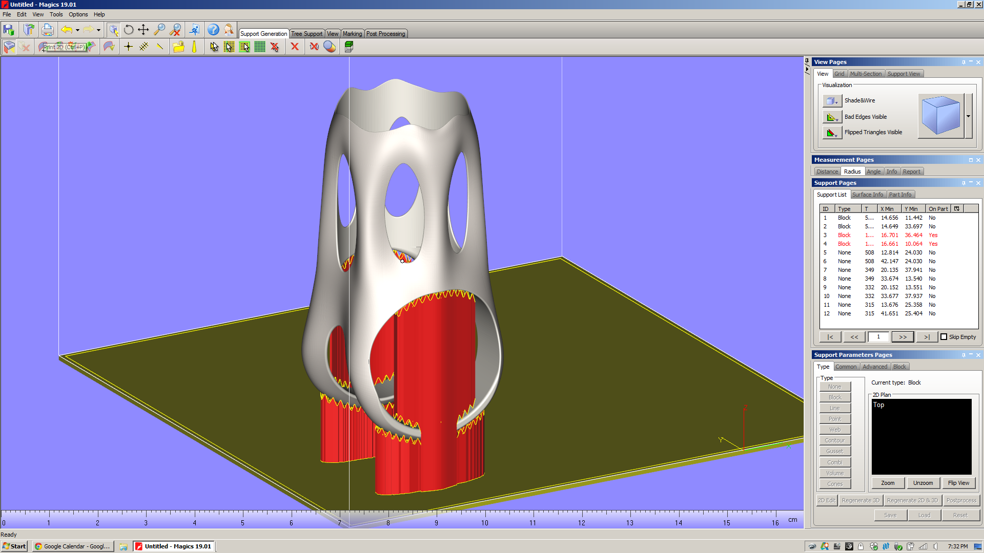
(I'm working on similar edits to the EBM build, but want to get a little clarification from Arcam on those point supports first.)
I can do a variety of other things to these supports, including "Rescale platform projection," which essentially flares the support in/out as it goes down to the platform. There are also a slew of parameters (hatching, hatching teeth, teeth synchronization, perforations, etc) which seem mostly designed to make the supports easier to remove from the part. All of these can be preset in the Machine Properties screen (which, frustratingly, isn't accessible when you're in Support Generation mode) or adjusted on a support-by-support basis from the "advanced" tool pages.
To be sure, I'm only scratching the surface on Magics' support generation features here. Magics will let you play with a *ton* of support parameters. I get the impression that there's a lot of nuance here, and that there are many parameters that you'd only play with in edge case builds. Regardless, the number of possibilities generated by varying just a few of the options is staggering; in order to know how they affect part quality, you'd need to run thousands upon thousands of test builds.
Eventually, it's very likely that Magics (or whatever replaces it) will have thermal & residual stress simulations built right into the software. Today, however, machine operators have remarkably little info about the finished part before they actually print it. Except...
Build time estimation
This is a key part of the additive design-for-manufacturing process. Knowing how long a part will take to print is a *huge* factor in what it costs, and is critical in comparing two build configurations for the same part.
Magics has a build time estimator, but it's not plug-and-play. Instead of shipping pre-loaded with estimates of how long a given machine will take to build a part, Magics requires the user to run "Learning Platforms" - and you need to own your own machine to do that. And, of course, I don't own a metal powder bed fusion machine.
The reason for this is that in order to estimate build time, you need to know how both the slicer and scanning strategy work - as well as mechanical factors like scanning speed and recoating time. And while certain machine manufacturers (see below) share this information with Materialise, for many it simply isn't worth it. They see those process parameters as valuable, and don't see the benefit of sharing that data with a third party software developer. Moreover, most of them can provide very accurate build time estimations in their own software, and the manufacturing engineers that use the machines take it as given that they need to use that at some point in the process anyway.
This strikes me as a big failing. Magics needs a way of sharing data about their builds: a public repository of machine parameters and build times. Without that - or without, on the other hand, convincing the machine manufacturers to share that data themselves - Magics is left with a huge disconnect between the build setup and the end product. This undercuts Magics' claim to be "The link between your CAD file and the printed part." If it lacks basic data on build speed for the most common machines in the industry, what exactly is it linking to?
So: As of the time I'm writing this, I've got emails out to a handful of the biggest metal powder bed fusion machine manufacturers in the industry, asking for Magics learning platforms. If anyone out there can share that data with me, please send me a note!
Build Processors
My demo doesn't include these, but they're worth touching on. For a few big machine manufacturers (Renishaw, SLM, and EOS), Materialise has developed build processors that are tuned to those machines' capabilities and specifications. Presumably, these companies provide Materialise with in-depth data about how their machines work, some of which is either patented or proprietary. Materialise then builds software modules that, through a few intermediate steps (the most notable of which are slicing and subdividing/hatching), produce a job file that can go directly to a machine.
Materialise bills the build processors as reducing complexity in the manufacturing life cycle, and allowing both Materialise and the machine manufacturers "to focus on their core competencies." Having not played with them myself, I can't really comment. I hope to learn more soon.
A few things Magics *can't* do
To reiterate: It's my impression that Materialise built Magics to fill a really big hole in the existing work chain, and the bottom line is that that work chain is something that no single party (let alone Materialise) created. It's also, in my opinion, *not* the right work chain for the future of additive manufacturing, and Magics' role in it highlights a lot of the problems in the industry today. Here are a few things that I noticed that Magics can't, for various obscure and not-so-obscure reasons (many of which are decidedly *not* Materialise's fault), do.
Understand the underlying design
This is something I've touched on in previous posts, but it struck me again when I was in the "supported area preview" screen. It's *very* likely that I could, with a relatively small amount of work, edit the underlying geometry in order to reduce the number of supports needed significantly. But I'm not aware of a way of showing downfacing regions in solid modeling software (Solidworks/Inventor, etc), and it's rather cumbersome to bounce back and forth between Magics and Inventor to try to optimize the design for additive.
All across the industry today, I hear people talk about design software that understands the intent of the designer, and responds to accommodate it. This may be feasible in the near future, but the bottom line is that Magics (as it stands now) is *not* part of that process chain. Once a designer transitions from parametric modeling to surface tessellations, all of the geometry data is lost. If manufacturability feedback (like the supported area preview screen) is provided in software that reads surface tessellations (as Magics does), then going back to edit the underlying parametric model is *always* going to be cumbersome - and necessary.
Understand/display surface quality issues due to orientation
In all additive processes that I'm aware of, surface finish will vary significantly depending on the orientation of a surface relative to the build direction. Given the layer thickness of the printed part, this is relatively straightforward to simulate - not to a high degree of precision, but with a good amount of accuracy, at least. Magics doesn't do this, and it leaves me feeling like I'm missing a key piece of information about the printed part. Sure, I can imagine what the part will look like if I just think about it for a minute, but it does strike me that having some indication of areas with high stepover (which will occur wherever a surface is oriented close to the XY plane) would be really helpful - and not particularly hard to implement (caveat: everything I said above about feature creep, etc).
Understand the place of additive in the process chain
This may seem like I'm splitting hairs, but I think it's worth reiterating: Magics bills itself as "The link between your CAD file and the printed part." It is NOT concerned with the end product, which in almost all cases will have additional (subtractive) processes performed on it.
Why does this matter? When I had this part EBM printed recently, both the saddle clamp cylinder and the seatpost cylinder came out undersized. I know now that one of two things needs to happen there: either I need to compensate for the printing process in the underlying model (by making the designed dimension larger than I actually want it to be), or I need to remove material from the as-printed part (by machining, grinding, or similar).
Magics doesn't know any of this. If it did, it might be able to give me intelligent advice on what surfaces to take extra care with - and which I should ignore, as they'll be machined away in the end regardless.
In the end, Magics is a piece of CAM software - but it only deals with one step in the production chain. Changing this is a monstrous, complex task, but it's one whose impact will be hugely positive.
So
Magics is pretty cool - it does a *ton* of really useful stuff. You'll note, also, that I'm basically not interested at all in its "fix" feature, which (I'm told) is used a lot with models that come out of Rhino.
But it's also representative of a lot of what's going on in industrial additive manufacturing today. This isn't Materialise's fault; it's just the way things evolved, and is the result of (I'm sure) a lot of collaboration, competition, and plain old hustling (all of which I fully support) in the industry over the past few decades.
Regardless, Magics is a place where you can see a lot of the implicit assumptions that industrial additive manufacturing has been built upon. More on this soon.