Manufacturing guy-at-large.

Photos from NYIO's trip to the Hudson Yards project

Added on by Spencer Wright.

Last week, the New York Infrastructure Observatory was lucky enough to tour the Hudson Yards Redevelopment project - the largest private real estate development project in US History. From my announcement email:

I just want to reiterate that: This is 26+ acres of active rail yard, on which Related Companies and Oxford Properties are building over 12 million square feet of office, residential, and retail space, designed by Kohn Pedersen Fox. And the trains underneath (did I mention that all of this development is being built on a huge platform supported by columns?) will keep running throughout construction.

The Hudson Yards project will remake the a big part of the NYC skyline, and includes large changes to the infrastructure in the area. It's a once in a generation project, and it was *really* great to see it in person.

You can see my photos (with captions, if you click them) below. Gabe Ochoa also posted a bunch on his blog, which I recommend checking out too!

Hudson Yards from the new 7 train entrance

Also: You should really read The Power Broker.

On PDFs

Added on by Spencer Wright.

I've written offhand things about PDFs before, but Ben Wellington is clear and straightforward in this post:

     You see, PDFs are where information goes to die, rather than to be used.

If you have something to communicate, think *really* hard about whether you're okay with it dying. This goes for *way* more than just public data, too. Product info, scientific research, industry knowledge... Put it in a PDF, and it's frozen.

This is why Gongkai AM is on GitHub. It's a weird platform for most people in R&D and engineering, but one that allows for *way* more flexibility and longevity. 

Rsk

Added on by Spencer Wright.

From NIST 89-4088, "Surface Finish Metrology Tutorial," a simple graphic showing the role of Rsk when evaluating surface texture:

Rsk describes surface texture skewness. Each of the above surfaces have the same roughness average (Ra), but they differ greatly in their skewness. Rsk describes this difference, allowing for a pitted surface to be distinguished from a spiky one.

This is useful.

Coming soon

Added on by Spencer Wright.

Today I *finally* found time to photograph the parts that I got back from MicroTek a few weeks ago:

As you can probably see, the part on the left is unfinished. In the middle is an intermediate finish (~25µ" Ra), and on the right is a fine finish (~1.5µ" Ra). All three of these parts were printed on Addaero's Arcam A2X; their raw finish is about 600µ" Ra. 

Incidentally, I'll note that photographing the surface finishes on these parts has been remarkably challenging. I probably need a strobe or something, but hey - it's a labor of love.

I'll be writing up the results in the next few weeks. Stay tuned!

Speaking

Added on by Spencer Wright.

Just a PSA: I'm speaking at three upcoming conferences! Give me a holler if you'll be at any of them - I'd love to chat.

  • Develop3D Live, 2016.03.31. Come to Warwick, UK and talk to the cream of the crop in CAD software.
  • AMUG, 2016.04.03-07. St. Louis! The biggest group of additive manufacturing users in the world. A *great* place to meet people working actively in AM, and trade process knowledge & expertise.
  • RAPID, 2016.05.17-19. North America's largest 3D printing event moves to Orlando. A great place to survey the industry and see what's coming up.

Good newsletters

Added on by Spencer Wright.

Prompted by Brendan, I wanted to list a few good email newsletters that I subscribe to and consistently enjoy. If you know of one that isn't on this list, give a holler and I'll check it out.

  • My own The Prepared <- shameless plug.
  • Reilly Brennan's Future of Transportation. Lot of autonomous car stuff here, but also great coverage of less hyped-up developments. I particularly like the "Patents & patent applications" section - mostly because it's a useful category of stuff, which I've really yet to develop for The Prepared.
  • Alexis Madrigal's Real Future, formerly Five Intriguing Things. Lot of obscure stuff here, all appropriately nerdy :)
  • Jon Russell's Asia Tech Review. Most of this is way beyond my interest level, but I like to keep more or less up to date on China and Jon does a good job at that.
  • Ingrid Burrington's Infrastructure Time. I'm not 100% sure that this is continuing beyond Ingrid's trip to the west, but I *really* liked her format and subject matter. 
  • Tilly Minute's New Yorker Minute. This got a lot of coverage recently as a way to cheat and act like you had read the New Yorker, but I find it really useful for it's real purpose: as a filter for what to devote my attention to.

I'll also mention Benedict Evan's newsletter. I don't really enjoy it much anymore, but you should be aware of nonetheless.

Not as hopelessly unyielding

Added on by Spencer Wright.

From a piece in the New Yorker about The Ford Foundation (lightly edited on my part):

The urge to change the world is normally thwarted by a near-insurmountable barricade of obstacles: failure of imagination, failure of courage, bad governments, bad planning, incompetence, corruption, fecklessness, the laws of nations, the laws of physics, the weight of history, inertia of all sorts, psychological unsuitability on the part of the would-be changer, the resistance of people who would lose from the change, the resistance of people who would benefit from it, the seduction of activities other than world-changing, lack of practical knowledge, lack of political skill, and lack of money.
Lack of money is a stubborn obstacle, but not as hopelessly unyielding as some of the others.

The above was written in the context social justice, but much of the paradox in this article translates to business too. While lack of money can certainly screw you up, it's more common to fail because of the multitude of other factors working against you - many of which are *far* more difficult to overcome than lack of money.

I don't want to be Amazon.

Added on by Spencer Wright.

GE CEO Jeff Immelt, talking with Henry Blodget:

There's a lot of people who have gotten fired thinking they're Jeff Bezos. So I don't want to be Amazon. I want to be GE.

This is right after Immelt refers to Bezos as someone he admires.

I've thought and written about corporate self awareness before (in particular with respect to Amazon and McMaster-Carr; see also the last paragraph or two of this old post about Pixar), but it's been increasingly on my mind recently. 

Knowing who you are - and having the fortitude to act accordingly - is key.

Joining nTopology

Added on by Spencer Wright.

Nine months ago I had one of those random conversations where you walk away feeling thrilled to be working in an industry with such compelling, intelligent people.

I had met Bradley before then (there are only so many people working on additive manufacturing in NYC), but only in passing. In the meantime our paths had diverged somewhat. He was working hard on design software, whereas I had focused on getting industrial AM experience through developing a physical product. But our approaches to the industry had converged, and we had developed a shared enthusiasm for addressing the technological problems in AM head on. We became instant allies, and started swapping emails on a weekly basis. 

In August, when nTopology launched their private beta program, I jumped at the chance to use it in my own designs. The engineering advantages of lattice structures were immediately evident, and nTopology's rule-based approach allowed me to quickly develop designs that met my functional goals. And as I spent more time with nTopology's software - and got to know Greg, Matt, Erik, and Abhi - my enthusiasm about what they were building only grew.

Today I'm thrilled to announce that I'm joining nTopology full time, to run business operations and help direct product strategy. nTopology's team, mission, and product are all precisely what I've been looking for since I began working on additive manufacturing, and I can't wait for the work we've got ahead of us.

For posterity, here are a few thoughts about nTopology's approach towards design for additive manufacturing:

  1. From the very beginning of my work in AM, it was evident that traditional CAD software would never let me design the kinds of parts I wanted. I was looking for variable density parts with targeted, anisotropic mechanical properties - things that feature-based CAD is fundamentally incapable of making. nTopology's lattice design software, on the other hand, can. 
  2. As the number of beams in a lattice structure increases beyond a handful, designing by engineering intuition alone becomes totally impractical. It's important, then, to run mechanical simulations early on, and use the results to drive the design directly. nTopology let me do just that.
  3. nTopology's approach towards optimization lets me, the engineer, set my own balance between manual and algorithmic design. This is key: when I intuitively know what the design should look like, I can take the reins. When I'd rather let simulation data drive, that's fine too. The engineering process is collaborative - the software is there to help, but gets out of the way when I need it to.
  4. Best of all, nTopology doesn't limit me to design optimization - it lets me design new structures and forms as well. That means far more flexibility for me. No longer am I locked into design decisions artificially early in my workflow, when a lot of the effects of those decisions are unknown. nTopology gives a fluid transition from mechanical CAD to DFM, and lets me truly consider - and adjust - my design's effectiveness and efficiency throughout the process.

The nTopology team has shown incredible progress in a tiny amount of time. They've built a powerful, valuable, and intuitive engineering tool in less than a year - and have set a trajectory that points towards a paradigm shift in additive manufacturing design.

In the coming months, I'll be writing more about our company, our mission, and our design workflow. If you're an engineer, developer, or UI designer interested in working on the future of CAD, send me a note or see our job postings on AngelList. To learn more about purchasing a license of nTopology Element, get in touch with me directly here.

Two years of The Prepared

Added on by Spencer Wright.

I began writing The Prepared, my weekly manufacturing newsletter, two years ago. I wrote a year-in-review of sorts this time last year, and thought I'd update it here.

First: The Prepared's subscriber list has increased by 185%, from 195 to 556. Its cumulative open and click rates are 52.3% (down from 54%) and 28.6% (down from 29%) respectively. 26 people unsubscribed in 2015.

Less tangibly but equally important, I feel notably closer to my subscribers than I did last year. I've connected with many of them by email or on Twitter, and have had more phone calls and coffees than I can keep track of. And as I've focused my area of interest, my audience has become more focused too. Increasingly, it includes people doing some of the most serious and interesting work in manufacturing today.

I also, for the first time, had a guest editor this year: Eric Weinhoffer, who filled in while I was on my honeymoon. Handing over the keys was good, and made me think about what The Prepared might look like if it weren't just my weekly manufacturing newsletter. I'm not sure whether I'll pursue a change in the near term (maintaining the current course is probably the path of least resistance for now), but even the possibility was interesting to consider.

As I wrote last year, The Prepared is "arguably the single most popular and useful thing that I do." It continually pushes me to make my knowledge base both broader and deeper, and has brought more people into my life than almost anything I've ever done.

Here's to another year!

Computer aided design

Added on by Spencer Wright.

Over the past week, one particular tweet has showed up in my timeline over and over:


The photos in this tweet have been public for over a year now. I've been aware of the project since last June; it was created by Arup, the fascinating global design firm (whose ownership structure is similarly fascinating). They needed a more efficient way to design and manufacture a whole series of nodes for a tensile structure, and for a variety of reasons (including, if I recall correctly, the fact that each node was both unique and difficult to manufacture conventionally) they decided to try out additive manufacturing. As it happens, I was lucky enough to speak to the designer (Salomé Galjaard) by phone a few months ago, and enjoyed hearing about the way they're thinking of applying AM to large construction projects.

In short: I'm a fan of the project, and love to see it get more exposure. There's something about the particular wording of Jo Liss's tweet, though, that is strange to me. Specifically, I find myself asking whether a computer did, indeed, design the new nodes.

(Note: I don't know Jo Liss and don't mean to be overly critical of her choice of wording; it's simply a jumping off point for some things I've been mulling over. I also don't believe that I have any proprietary or particularly insightful information about how Arup went about designing or manufacturing the nodes in question.)

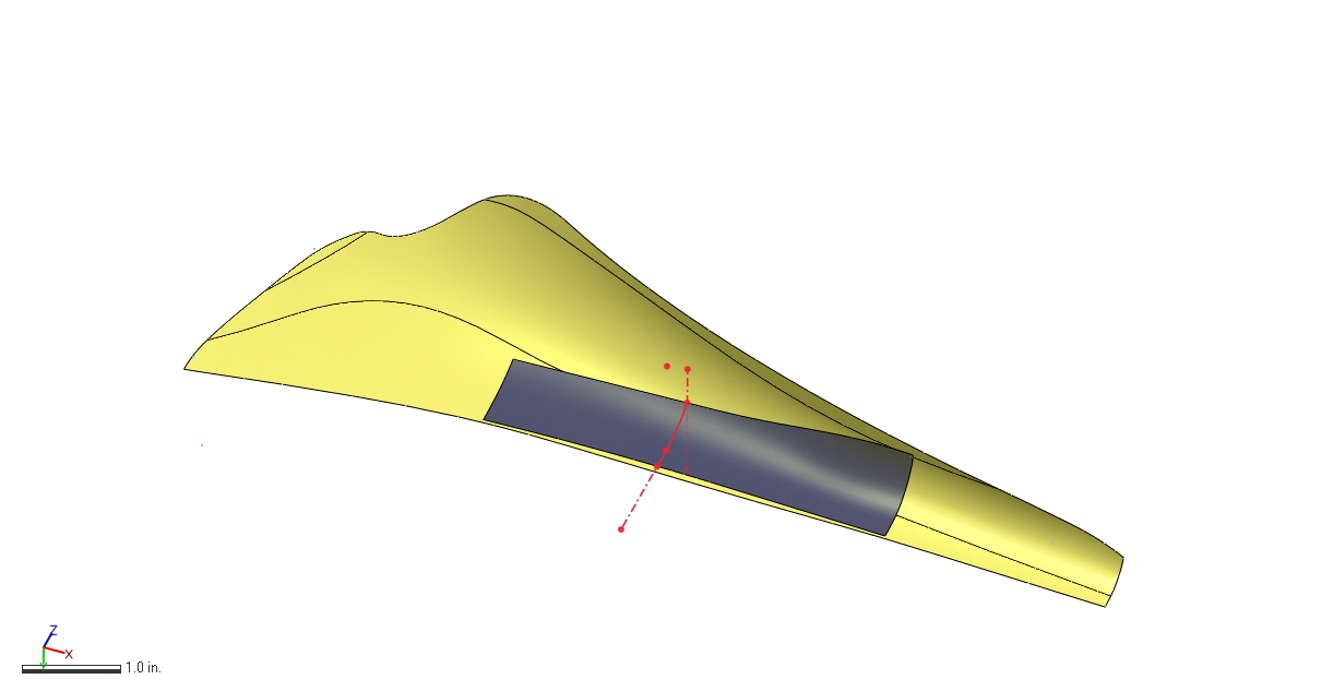
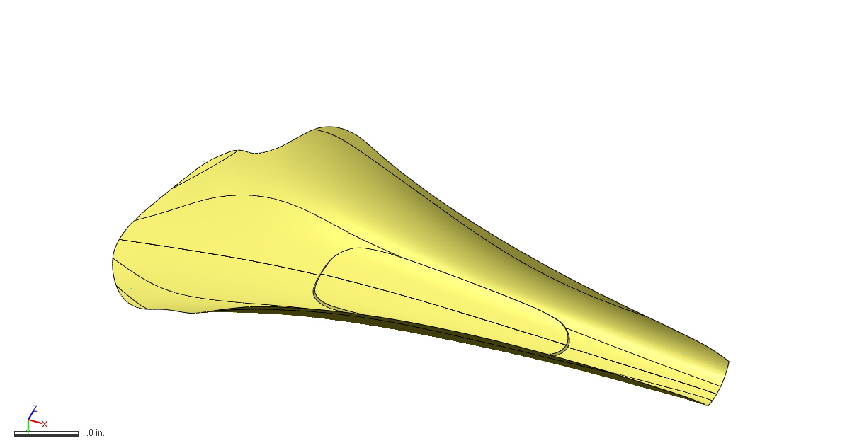
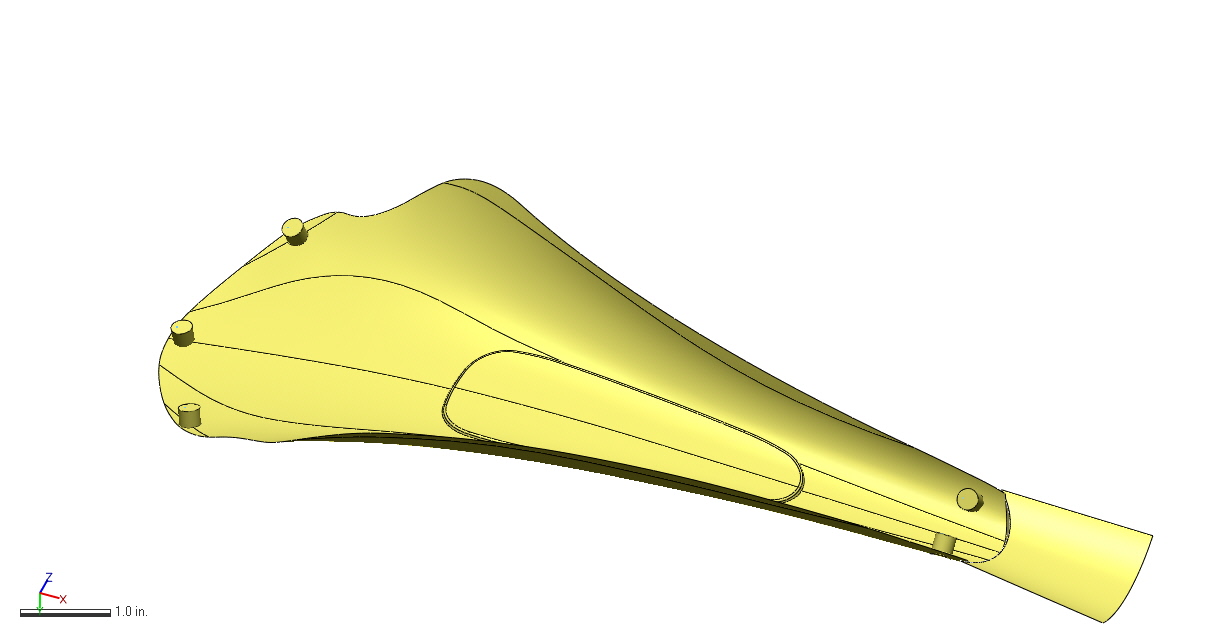
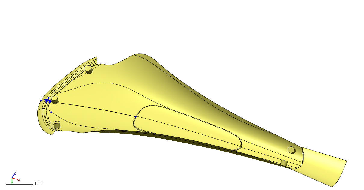
As far as I can tell, Arup's process worked like so: Engineers modeled a design space, defined boundary conditions at the attachment points (which were predefined), and applied a number of loading conditions to the part. Here the story gets less clear; some reports mention topology optimization, and others say that Arup worked with Within (which is *not* topology optimization). My suspicion is that they used something like solidThinking Inspire to create a design concept, and then modeled the final part manually in SolidWorks or similar. Regardless, we can be nearly sure that the model that was printed was indeed designed by a human; that is, the actual shapes and curves we see in the part on the right were explicitly defined by an actual engineer, NOT by a piece of software. This is because nearly every engineered component in AEC needs to be documented using traditional CAD techniques, and neither Within nor solidThinking (nor most of the design optimization industry) supports CAD export. As a result, most parts that could be said to be "designed by a computer" are really merely sketched by a computer, while the actual design & documentation is done by a human.

This may seem like a small quibble, but it's far from trivial. Optimization (whether shape, topology, or parametric) software is expensive, and as a result most of the applications where it's being adopted involve expensive end products: airplanes, bridges, hip implants, and the like. Not coincidentally, those products tend to have stringent performance requirements - which themselves are often highly regulated. Regulation means documentation, and regulating bodies tend not to be (for totally legitimate reasons which are a bit beyond the scope of this blog post) particularly impressed with some computer generated concept model in STL or OBJ format. They want real CAD data, annotated by the designer and signed off by a string of his or her colleagues. And we simply haven't even started to figure out how to get a computer to do any of that stuff.

I'm reminded here also of something that I've spent a bunch of time considering over the past six months. The name "CAD" (for Computer Aided Design) implies that SolidWorks and Inventor and Siemens NX are actively helping humans design stuff. To me, this means making actual design decisions, like where to put a particular feature or what size and shape an object should be. But the vast majority of the time that isn't the case at all. Instead, traditional CAD packages are concerned primarily with helping engineers to document the decisions that they've already made.

The implications of this are huge. Traditional CAD never had to find ways for the user to communicate design intent; they only needed to make it easy for me to, for instance, create a form that transitions seamlessly from one size and shape to another. For decades, that's been totally fine: the manufacturing methods that we had were primarily feature based, and the range of features that we've been good at making (by milling, turning, grinding, welding, etc) are very similar to the range of features that CAD packages were capable of documenting.

But additive manufacturing doesn't operate in terms of features. It deals with mass, and that mass is deposited layer by layer (with the exception of technologies like directed energy deposition, which is different in some ways but still not at all feature based). As a result, it becomes increasingly advantageous to work directly from design intent, and to optimize the design not feature by feature but instead holistically. 

One major philosophical underpinning of most optimization software (like both Within and solidThinking Inspire) is that the process of optimizing mass distribution to meet some set of design intentions (namely mechanical strength and mass, though longtime readers of this blog will know that I feel that manufacturability, aesthetics, and supply chain complexity must be considered in this calculation as well) is a task better suited to software than to humans. To that effect, they are squarely opposed to the history of Computer Aided Documentation. They want CAD software to be making actual design decisions, presumably with the input and guidance of the engineer.

If it's not clear, I agree with the movement towards true computer aided design. But CAD vendors will need to overcome a number of roadblocks before I'd be comfortable saying that my computer designs anything in particular:

First, we need user interfaces that allow engineers to effectively communicate design intent. Traditional CAD packages never needed this, and optimization software has only just begun the task of rethinking how engineers tell their computers what kind of decisions they need them to make. 

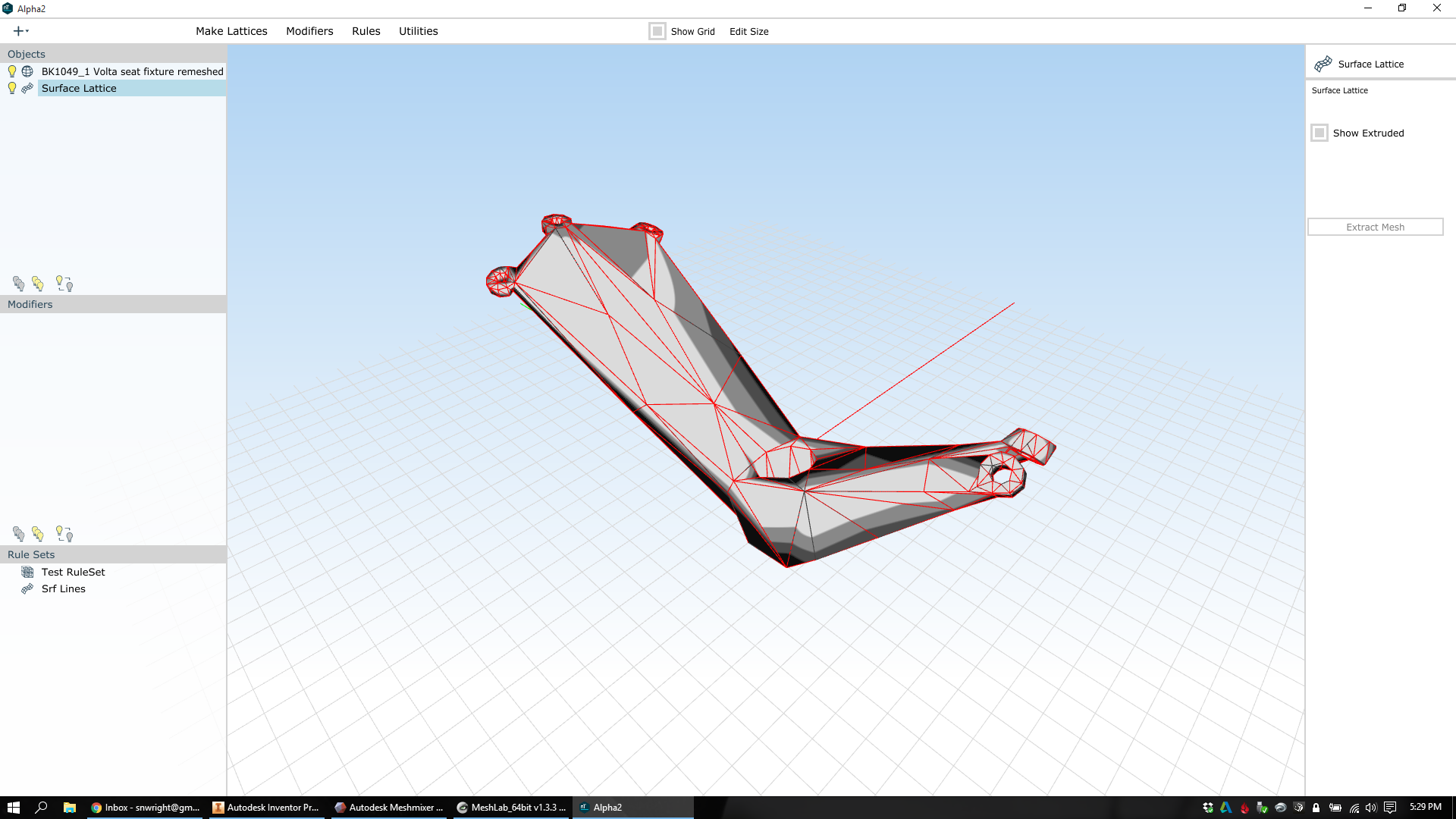
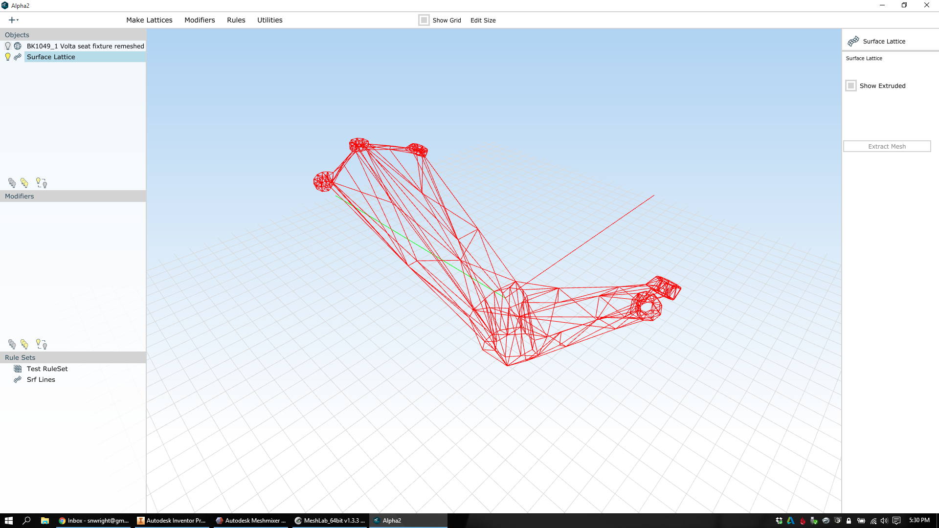
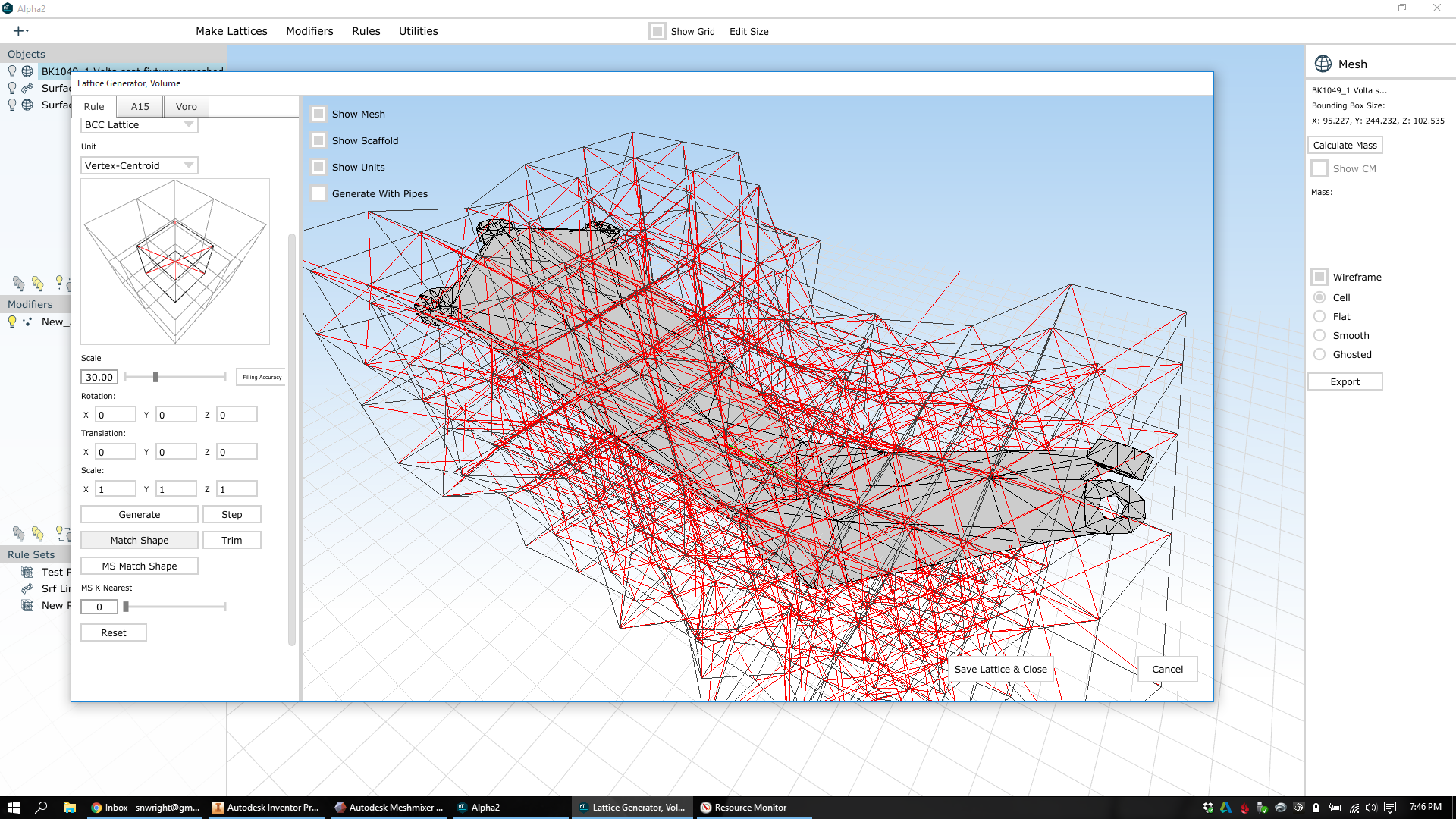
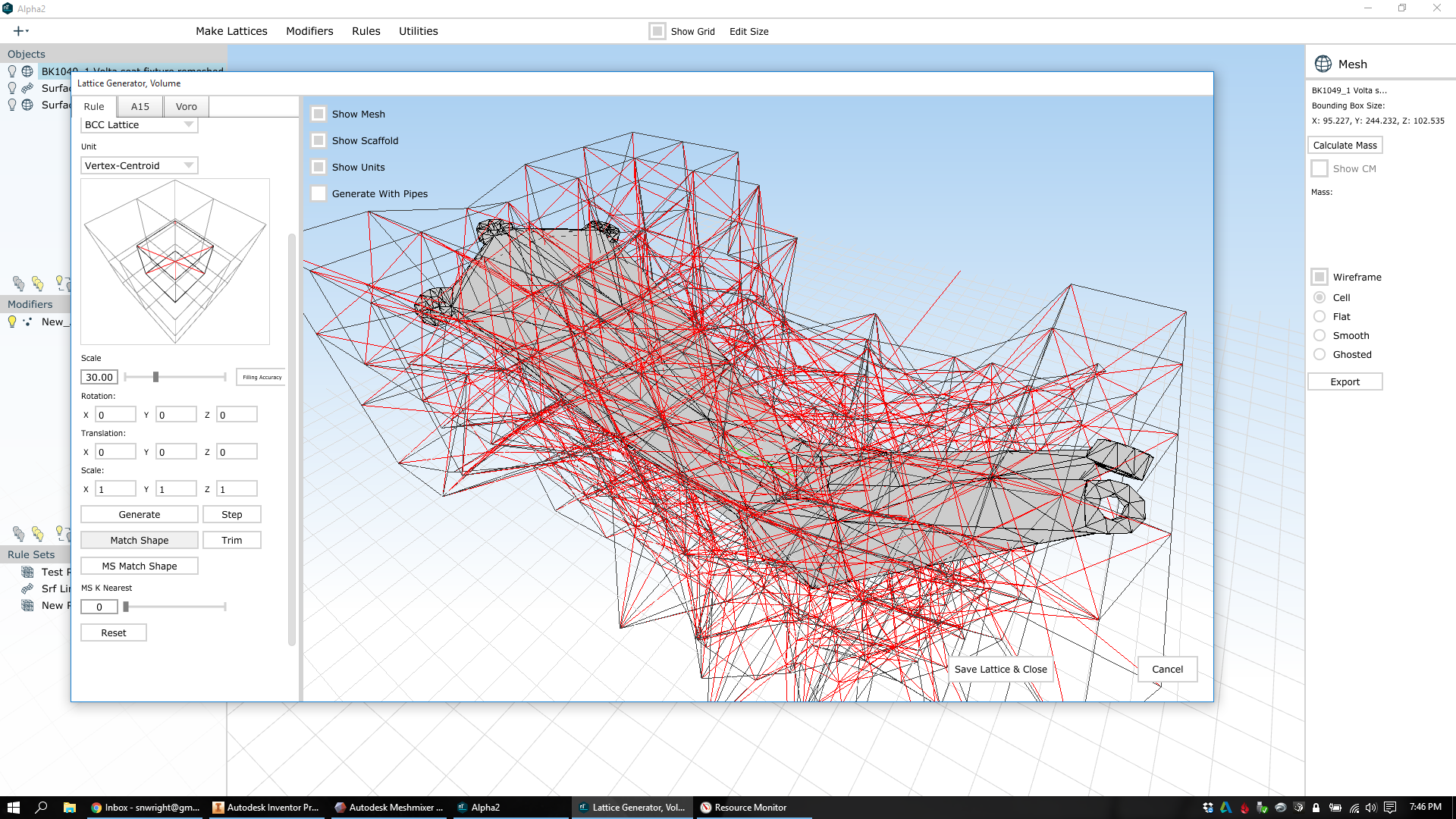
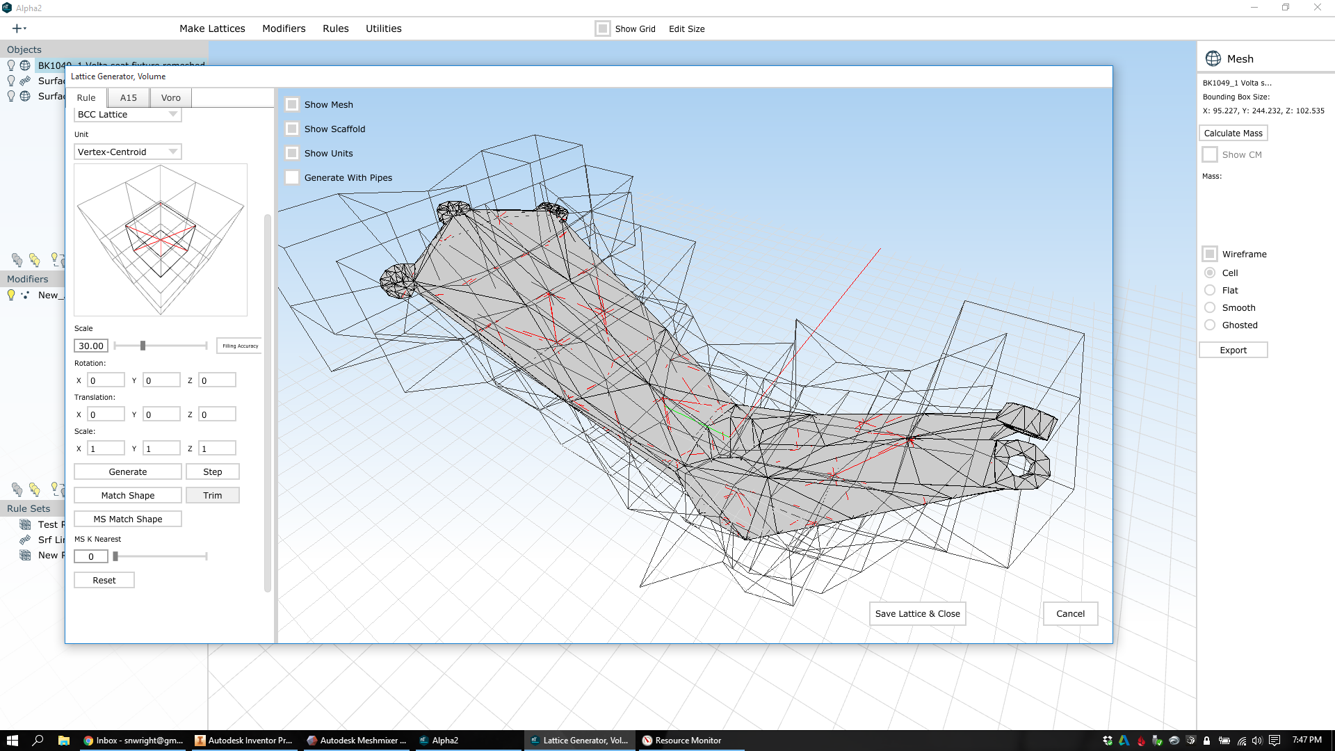
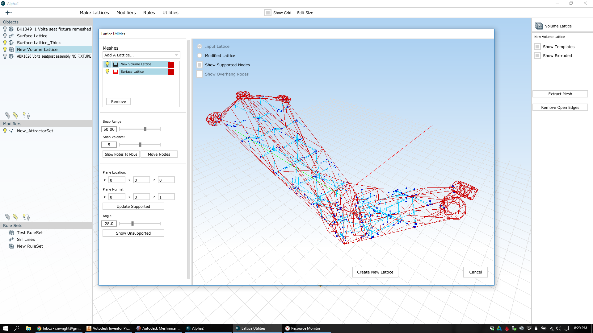
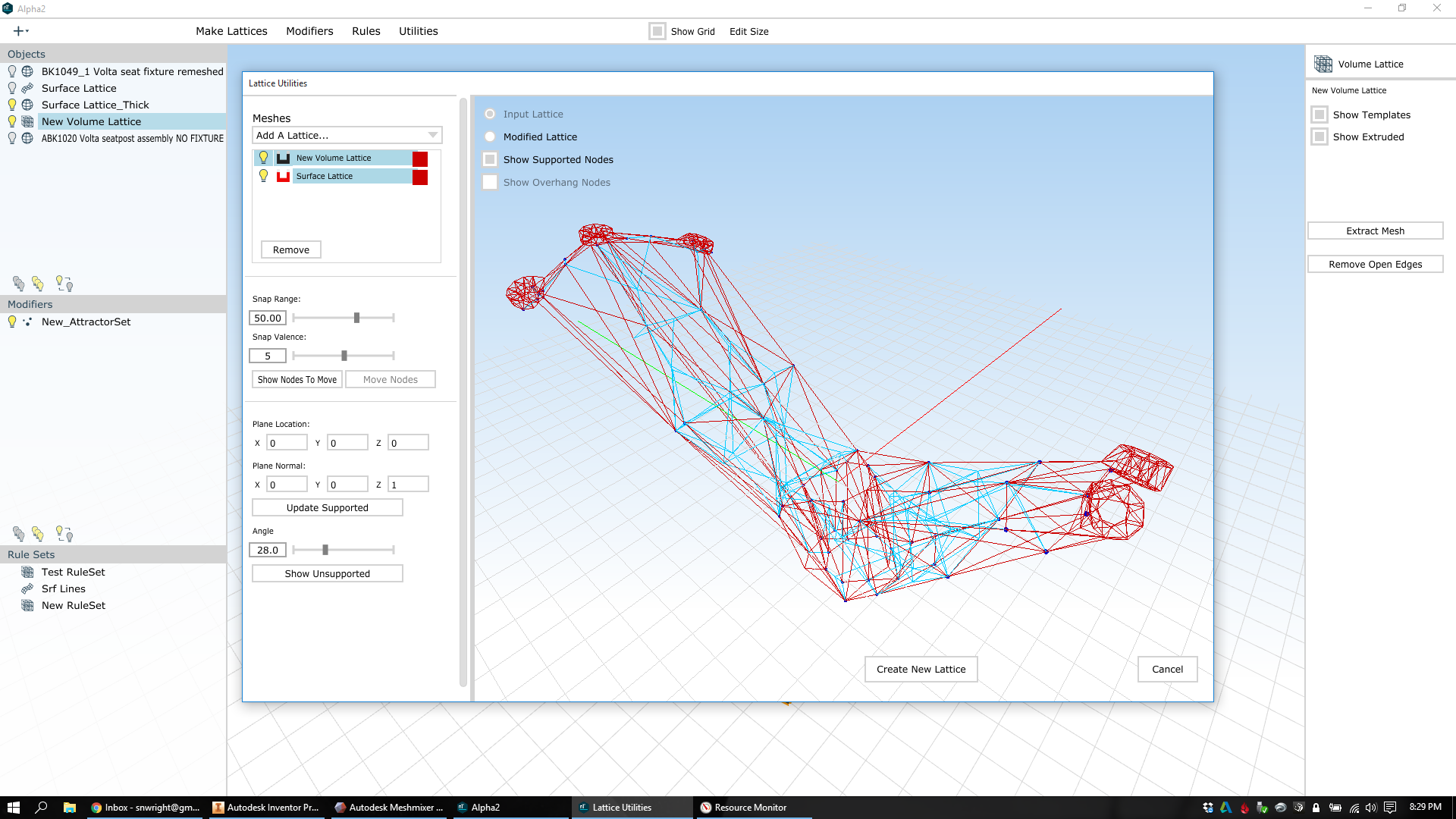
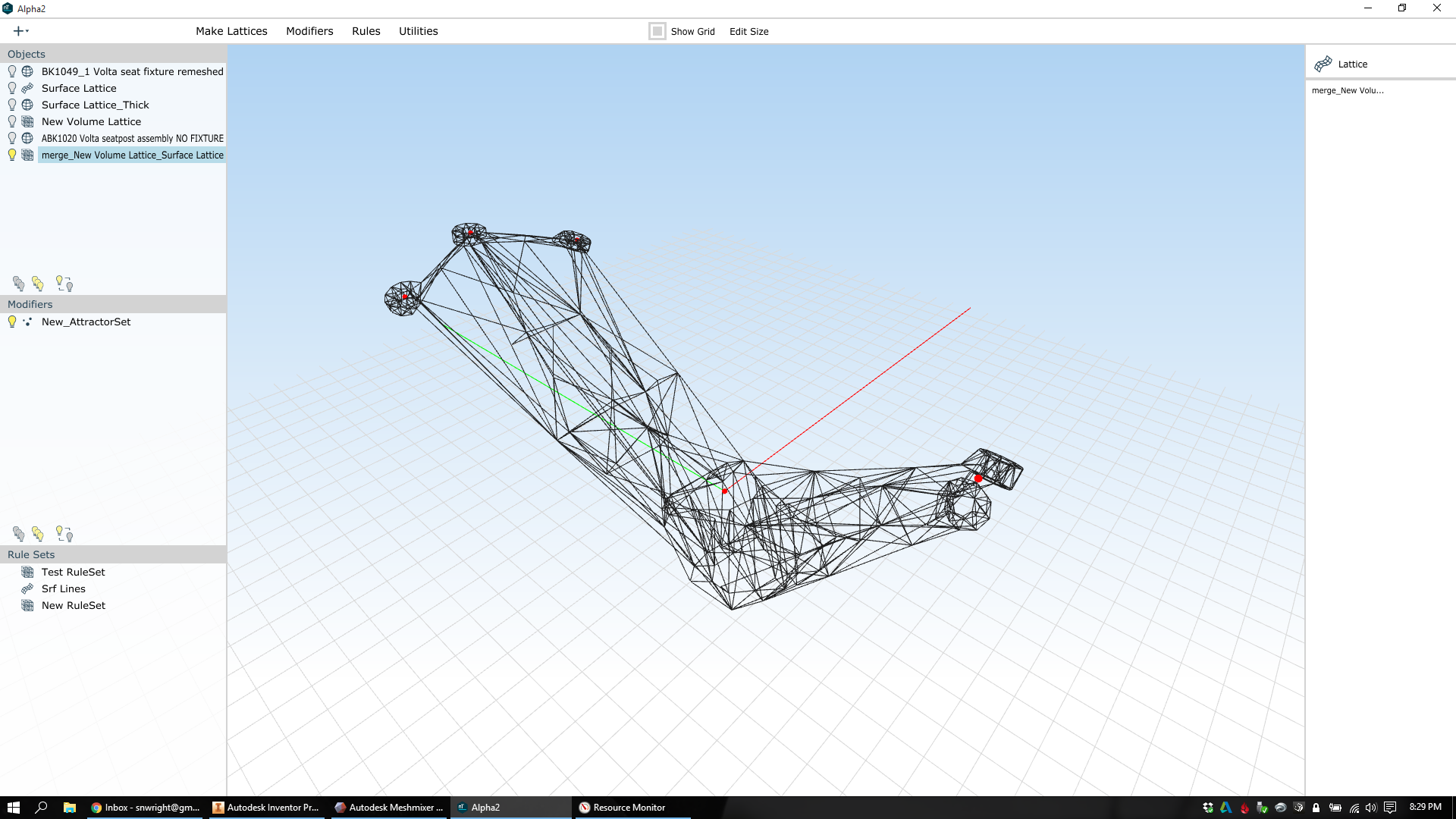
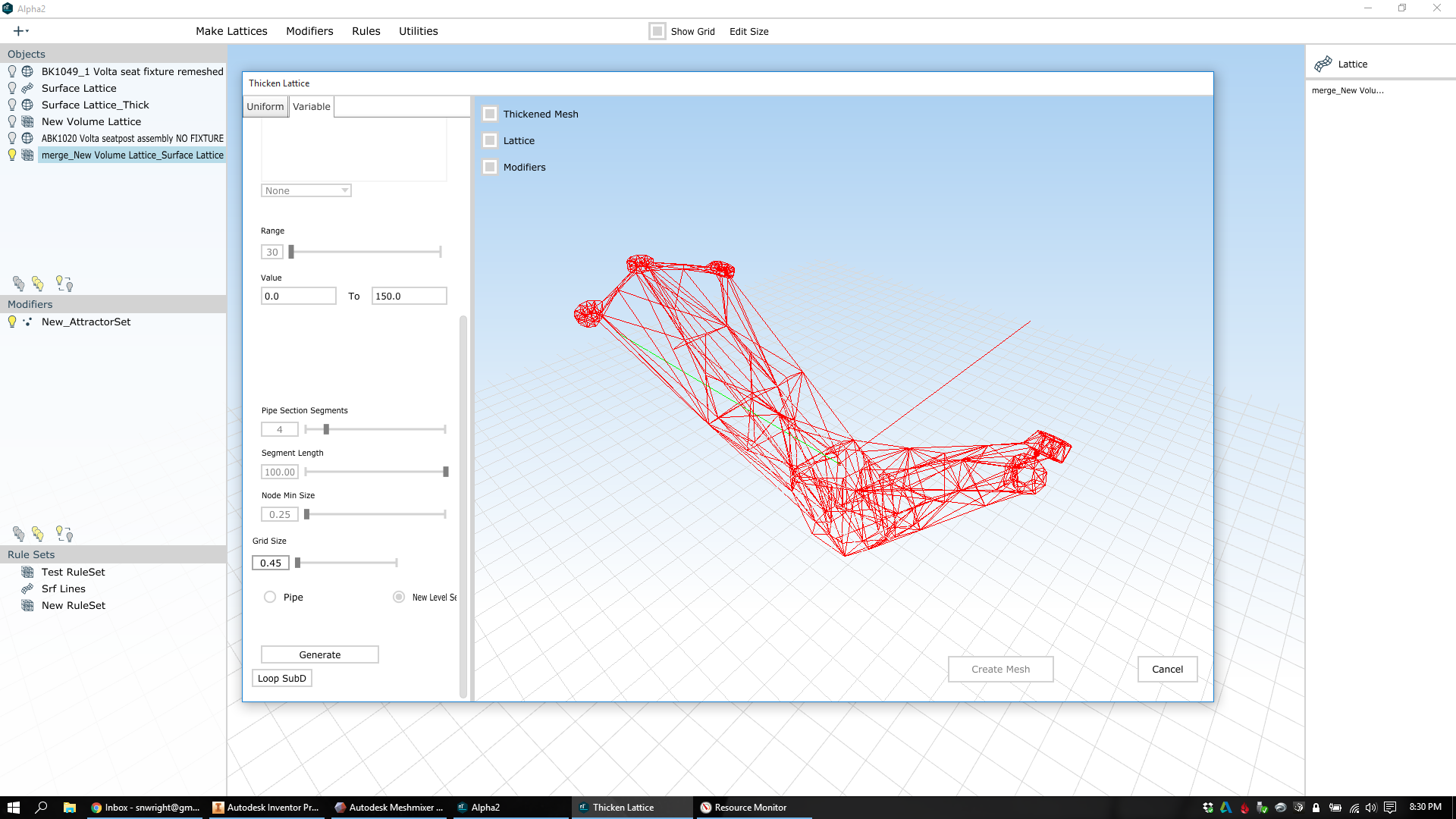
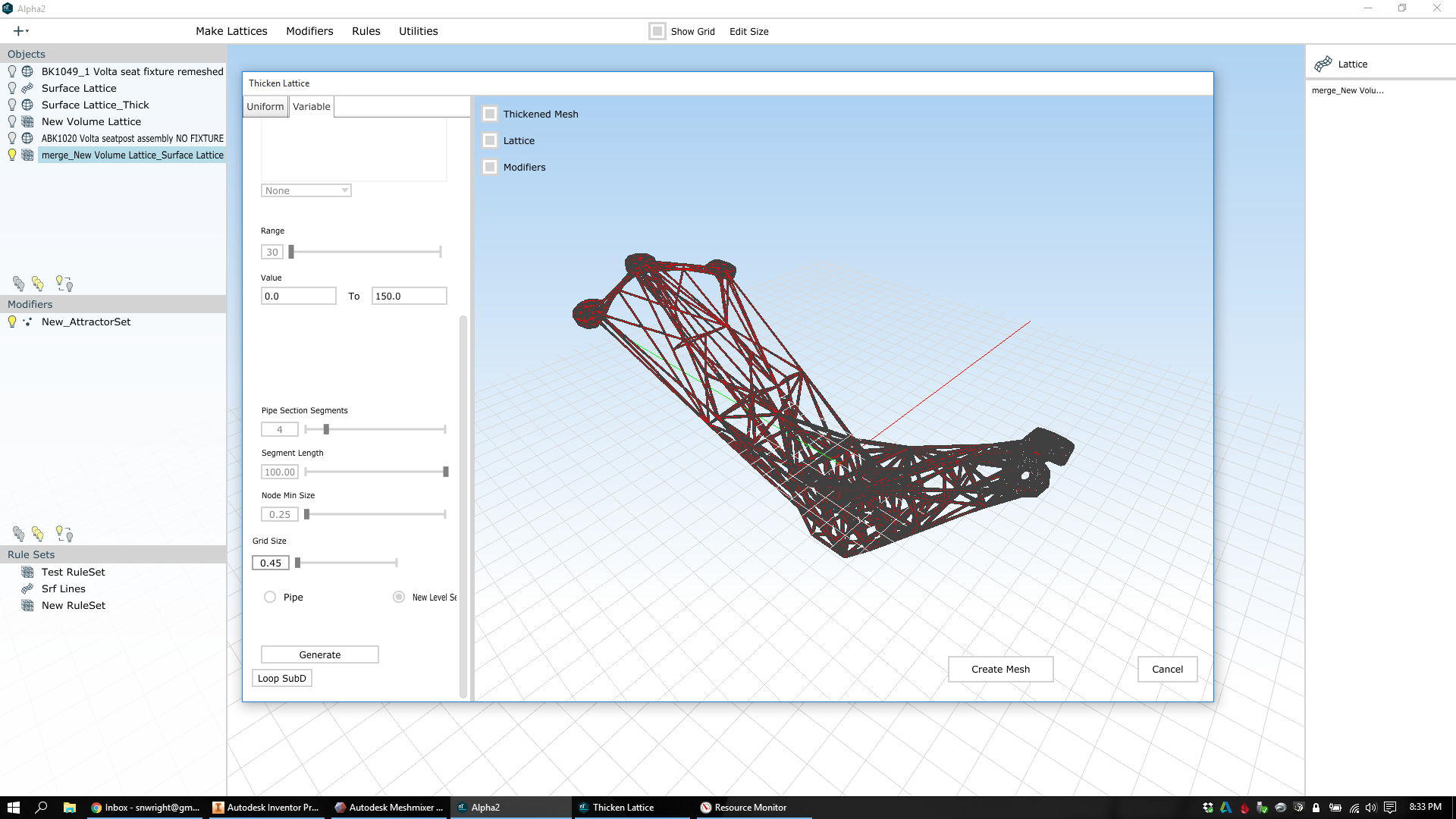
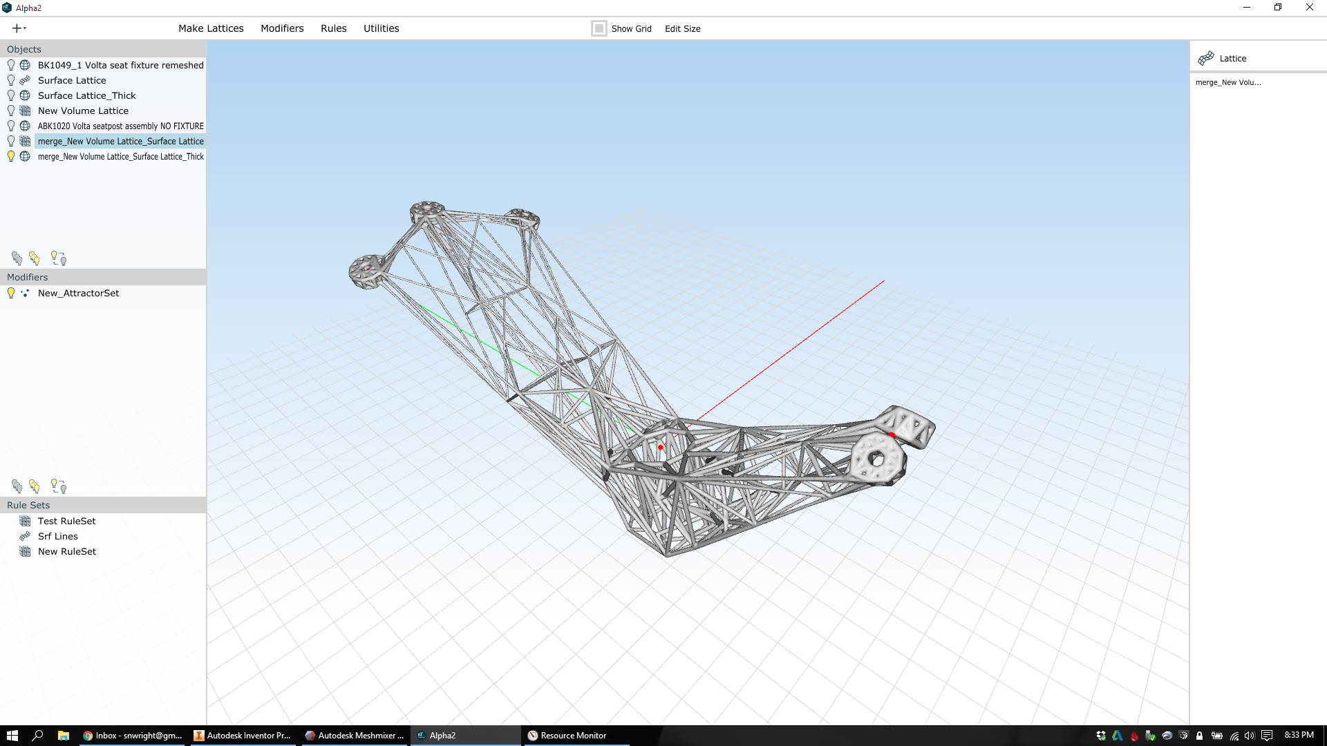
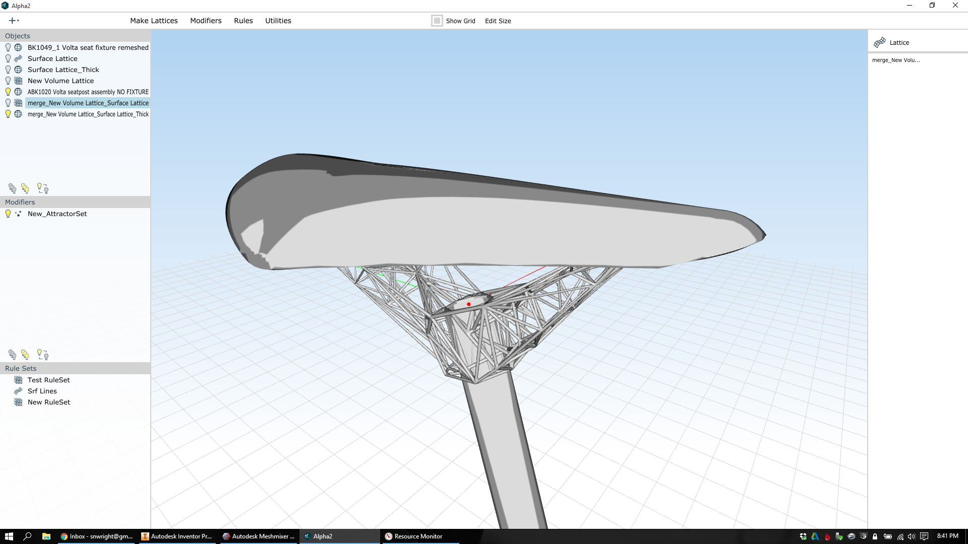
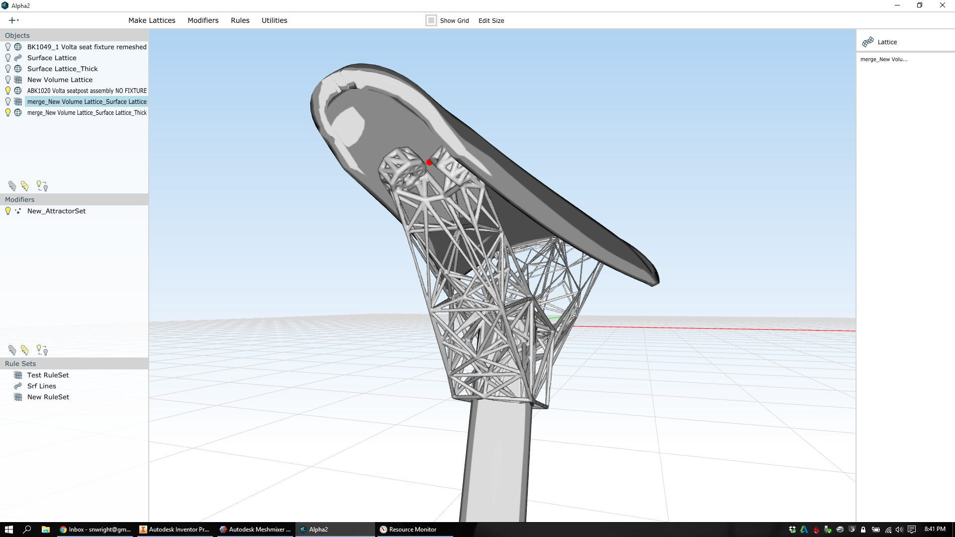
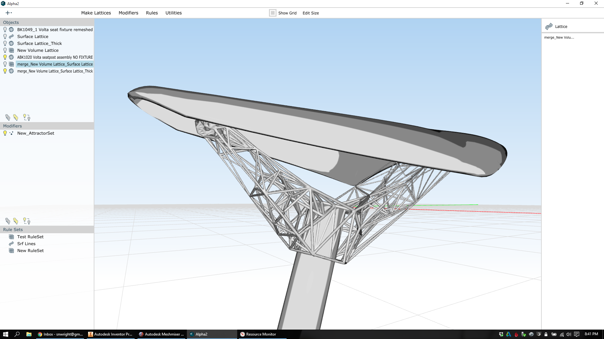
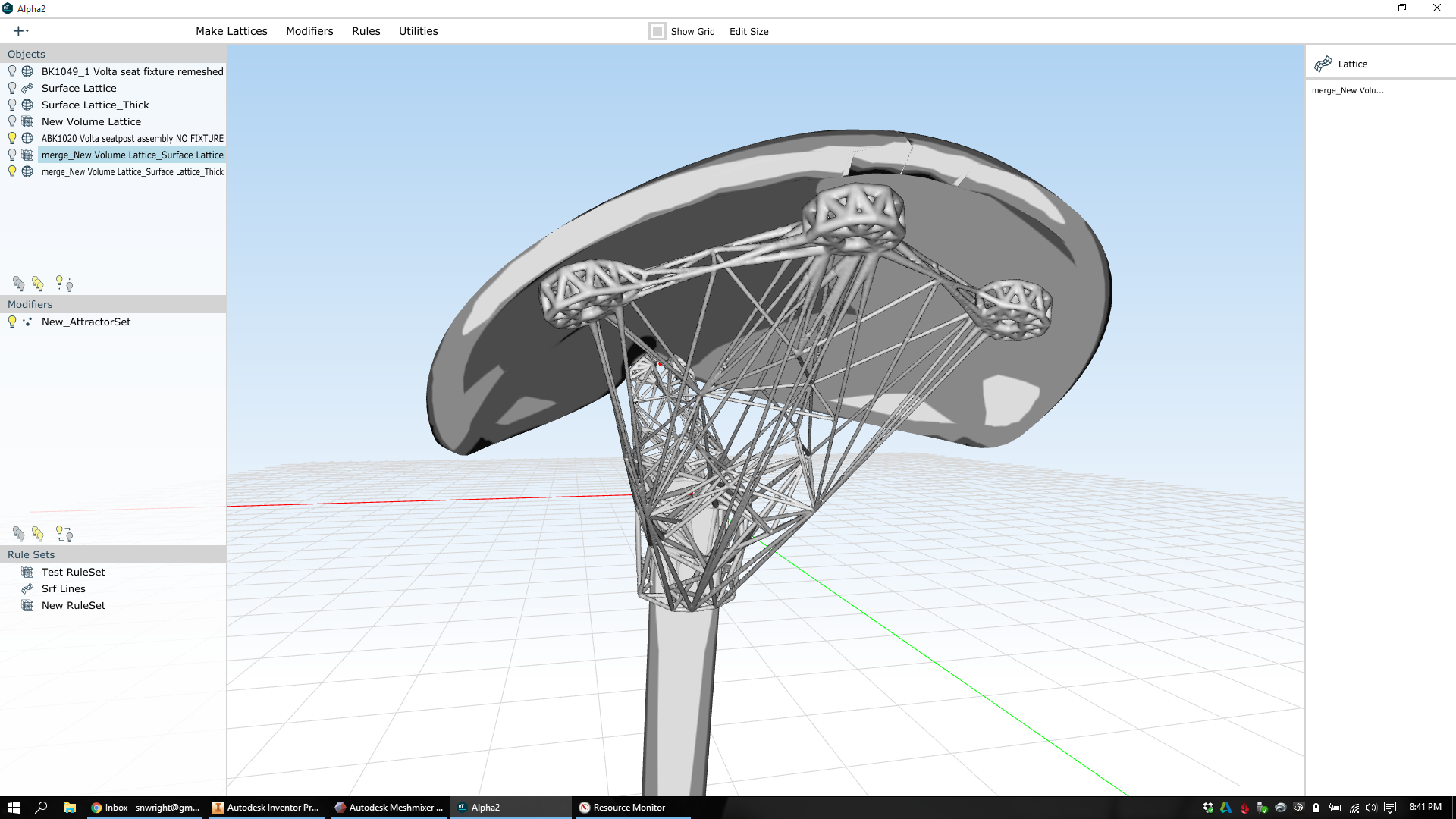
Second, we need to expand the number of variables we're optimizing for. Ultimately I believe this means iteratively focusing on one or two variables at a time, as the curse of dimensionality will make high dimensional optimization impractical for the foreseeable future. It's because of this that I'm bullish on parametric lattice optimization (and nTopology), which optimizes strength and weight on lattice structures that are (given input from the engineer) inherently manufacturable and structurally efficient.

Third, we need a new paradigm for documentation. This is for a few reasons. To start, the kinds of freeform & lattice structures that additive manufacturing can produce don't lend themselves to traditional three view 2D drawings. But in addition, there's a growing desire [citation needed] within engineering organizations to unify the design and documentation processes in some way - to make the model itself into a repository for its own design documentation.

These are big, difficult problems. But they're incredibly important to the advancement of functionally driven design, and to the integration of additive manufacturing's advantages (which are significant) into high value industries. And with some dedicated work by people across advanced design and manufacturing, I hope to see substantive progress soon :)


Thanks to Steve Taub and MH McQuiston for helping to crystalize some of the ideas in this post.

After publishing this post, I got into two interesting twitter conversations about it - one with Ryan Schmidt, and the other with Kevin Quigley. Both of them know a lot about these subjects; I recommend checking the threads out.

Photos from a visit to CCAT

Added on by Spencer Wright.

A few months back I had the pleasure of visiting the Connecticut Center for Advanced Technology, which is located on the UTC/Pratt & Whitney East Hartford campus. CCAT began as a facility focused on researching laser drilling, but has moved deeper into 3D printing, and specifically directed energy deposition, in the past few years. 

In addition to a full subtractive (manual and CNC) shop, CCAT has a few cool additive tools that I was particularly interested in. The first is an Optomec 850R LENS system. The 850R is a large format directed energy deposition machine which can be used for both new parts and repairs. It's also useful for material development, as DED machines can create parts with a small amount of powder (while powder bed fusion machines generally require a large amount of powder).

(Click on the photos for larger versions + descriptions)

The other thing I was excited to see was their Kuka HA30 robot, which has a coaxial laser cladding head attached to it. This robot can be used for either etching/engraving or cladding, meaning that it can either subtract or add material to a part. Especially when combined with the two-axis rotary table shown below, this thing can create some really complex parts.

It was really cool seeing these specialized technologies being used in real life. Thanks to CCAT for having me!

Photos from an antenna factory in Shenzhen

Added on by Spencer Wright.

This past July, Zach and I visited The Public Radio's antenna supplier in Shenzhen. I had only a vague idea of how antennas were made, and it was interesting to see the process in person. It was also fascinating to see a shop that relied so much on manual and mechanically driven machinery. 

A few observations:

  • This shop manufactures a variety of parts, with the defining feature being that they're made of tubing. For our antennas, the process works basically like this:
    • Tubing is bundled together with zipties and cut to length by wire EDM.
    • Tubing ends are swaged in/out.
    • Sections are assembled into a single telescoping unit
    • Meanwhile, end fittings are manufactured from solid stock. This happens either on the automatic turret lathes, or on single-operation manual machines (lathes/drill presses).
    • End fittings are installed on the telescoping antennas, again using swaging/forming processes.
  • The whole operation was decidedly low tech and manual - almost disturbingly so. It would seem very difficult to control quality - which I guess should be expected when you're looking at a niche, and rather inexpensive, commodity product.

A few of the photos have notes on them - click to show.

Murray Hill

Added on by Spencer Wright.

I'm reading The Idea Factory, and this description of Bell Labs' Murray Hill facility jumped out at me:

Kelly, Buckley, and Jewett were of the mind that Bell Labs would soon become - or was already - the largest and most advanced research organization in the world. As they toured industrial labs in the United States and Europe in the mid-1930s, seeking ideas for their own project, their opinions were reinforced. They wanted the new building to reflect the Labs' lofty status and academic standing - "surroundings more suggestive of a university than a factory," in Buckley's words, but with a slight but significant difference. "No attempt has been made to achieve the character of a university campus with its separate buildings," Buckley told Jewett. "On the contrary, all buildings have been connected so as to avoid fixed geographical delineation between departments and to encourage free interchange and close contact among them." The physicists and chemists and mathematicians were not meant to avoid one another, in other words, and the research people were not meant to evade the development people.
By intention, everyone would be in one another's way. Members of the technical staff would often have both laboratories and small offices - but these might be in different corridors, therefore making it necessary to walk between the two, and all but assuring a chance encounter or two with a colleague during the commute. By the same token, the long corridor for the wing that would house many of the physics researchers was intentionally made to be seven hundred feet in length. It was so long that to look down it from one end was to see the other end disappear at a vanishing point. Traveling its length without encountering a number of acquaintances, problems, diversions, and ideas would be almost impossible. Then again, that was the point. Walking down that impossibly long tiled corridor, a scientist on his way to lunch in the Murray Hill cafeteria was like a magnet rolling past iron filings.

Sounds like my kind of place.

Photos from a speaker factory in Dongguan

Added on by Spencer Wright.

This past July, Zach and I took a trip to the Pearl River Delta to visit, among other things (see one, two), the factory in Dongguan that made the speakers for The Public Radio. Below are some long overdue photos from the visit, along with whatever comments I can muster up from memory. 

Note: if you click on the photos, you can seem them larger. Some also have my own notes on them too.

Like most factories I've visited in both China and Taiwan, this one comprised a cluster of buildings around a large concrete courtyard. Immediately inside the gate on the right hand side (out of view of the photos below) was the office building; to its left was the assembly shop, then dormitories, then a building that housed the toolroom and the injection molding line.

We started our tour in the office building. I didn't get any photos of the conference areas, where we spent a good portion of the visit (we needed to discuss a redesign of the speaker, which was going to require new tooling and a few other changes). We dropped our bags there and introduced ourselves, and then went upstairs to see the R&D area.

There were a *lot* of different speakers here. The main part of the R&D area housed a few cubicles, each of which seemed to have more product on it than the last. There was also a small workshop area for assembling sample units, a semi soundproof chamber, and a listening room.

Our supplier had on site tooling and injection molding. We didn't even realize this coming in, but it was great to see that they could have full control of their own process and design. 

Tooling is then sent next door to the injection molding line. Our factory was in the process of installing automated part handling on a few of their machines, which was interesting to see in real time. 

Then up to the speaker assembly area. They had (if I recall correctly) six moving assembly lines, which were broken up by the size of the speakers they could handle. Speaker assembly is mostly a process of gluing different components together, so there were a bunch of specialized tools that would inject adhesive in a controlled manner.

Back outside. The office is on the left here, then the injection molding line & toolroom, then the assembly shop.

Heading back to Dongguan that afternoon, I was impressed with what we had seen. This was a pretty small business, and we were a tiny customer. They (like most of the people we talked to in China) were somewhat confused with our product, but they had a good attitude and definitely understood why we wanted to make the changes we had asked for - and were interested in helping us get what we wanted.

Why Gemba

Added on by Spencer Wright.

I’ve been working a lot on the mechanics of how Gemba (my idea for a shared industrial 3D printing space in NYC) would work, and it struck me that I should probably write down why I want to do this in the first place. These are intended to be mostly personal reasons; here goes.

I like building stuff. Having a measurable output is a big motivator for me, and I find myself similarly drawn to people who are building stuff too. 

In particular, I like building stuff that’s valuable. I’m being intentionally abstract here: my blog is valuable, and so are manufactured goods, and so is the process and craft that one learns by manufacturing things, and so is the management expertise that one develops through years of working on hard problems, and so is the social capital that one accrues by being a considerate, dedicated, hardworking person. Ideally, I’d structure my life such that I can focus on one of these things and still let the others flourish; the compound value would be exponential.

I also, for purely selfish reasons, want to make an impact on long term global problems. Like any new manufacturing method, I believe that metal AM has the potential to make a positive impact on our ability to make long term valuable products (lightweight transportation systems, patient specific orthopedic implants, etc) more effectively and efficiently. And given my experiences over the past two years, I think I can play a significant role in increasing its rate of adoption and maturity.

It’s possible I could do this in a private environment - working full time on a single, proprietary solution. But in order to create a larger impact more quickly, I feel it’s important to work alongside others. I want to work in the MIT Building 20 of advanced manufacturing. I believe that my own output - and my quality of life - will be much improved as a result.

It’s no secret that New York City is no longer the center of manufacturing that it once was. But at the same time we’ve got some of the nation’s top minds in architecture, engineering, and construction, and our 3D printing community is one of the largest in the world. We’re also the geographic center of a huge network of manufacturers (large and small) that populate the I95 corridor, and we remain *the* cultural magnet for young engineers graduating from any of the top tier schools in the Northeast.

These factors - and the anecdotal evidence that myself, and people like me, want a place to work on industrial grade problems - will give Gemba NYC a robust technical pipeline and talent pool. In addition, though, New York adds a significant edge when it comes to business model and marketing leadership. We (and by we I mean a combination of companies like Makerbot and GE) have been at the forefront of a total rebranding of additive manufacturing - one which has brought a huge influx of investment, talent, and ideas. New York also has a proven track record in developing and launching just in time, direct to consumer businesses (see Warby Parker, Casper, Blue Apron, etc) that shorten supply chains and are more responsive to end user needs. Additive manufacturing will need this expertise; New York will provide it.

In short: I believe in the technology; I believe in the power of working in close proximity with others in the industry; I believe in New York City’s ability to lead technical and commercial solutions to the problems facing industrial AM.

I want to increase the success rate of industrial additive manufacturing. I think it’ll be fun, and interesting, and will benefit both myself and humanity as a whole. And in order to increase my own success rate, I want create a space where dedicated, forward thinking companies and individuals can experiment with and develop solutions to the problems facing AM today.

This will require a big effort, and I’ll need the involvement of people and companies much more experienced than myself. I’m looking forward to hearing what their interests are, and developing a space and financial model that serves us all well. If the things above resonate with you, get in touch - I’d love to chat.

On Optimization

Added on by Spencer Wright.

As I've explored further into the obscure regions of design for additive manufacturing, I've been thinking a lot about the philosophical underpinnings of optimization, and the role that design optimization can play in product development. Optimization is in the air today; the major CAD vendors all seem to have an offering which purports to create "the ideal part" with "optimum relation between weight, stiffness and dynamic behavior" and "the aesthetics you want." These promises are attractive for seemingly obvious reasons, but it's less clear how design optimization (at least as it exists today) actually affects the product development process.

Product development inherently involves a three-way compromise between quality, cost, and speed. The most critical trait of a product manager is the ability to establish a balance between these three variables, and then find ways to maintain it.

Understanding the strengths and limitations of manufacturing processes is, then, invaluable to me as a product manager. Given infinite resources, people are pretty good at making just about anything that can be designed; there are designers out there who make very successful careers just by pushing the boundaries of what is possible, and employing talented manufacturing engineers to figure out how to bring their designs into existence. But in my own experience, the more I understand and plan for the manufacturing process, the easier it has been to maintain a balance between quality and cost - and hence to create an optimal end product.

All of which makes me feel a strange disconnect when I encounter today's design optimization software, which always seems to focus specifically on creating Platonically perfect parts - with no regard for manufacturability or cost.

To be fair, traditional CAD programs don't usually have a strong manufacturability feedback loop either. Inventor, SolidWorks, and NX are all perfectly happy with me designing a fillet with a radius of .24999995" - when a 1/4" radius would work just fine and cost much less to manufacture. In this way, traditional CAD requires the user to have an understanding of the manufacturability of the features that she designs - a requirement which, given the maturity and nature of conventional manufacturing methods, is not unreasonable.

But the combination of additive manufacturing on one hand, and generative design on the other, produces vastly different effects. No longer does a designer work on features per se. There's no fillet to design in the first place, only material to move around in 3D space. Moreover, the complex interaction between a part's geometry and its orientation on the build platform produce manufacturability problems (overhanging faces and thermal stresses, to name two) that are difficult to predict - and much harder to keep in mind than things like "when you design fillets, make their radii round numbers."

The remarkable thing about AM design optimization software, then, isn't that it allows me to create expensive designs - it's that these kinds of manufacturing factors (orientation to the build platform, and the structural and thermal effects that it produces) aren't treated as things which need to be optimized for at all.

The purpose of optimization should be to help me, as a product manager, design optimal *products* - not to chase some Platonic ideal.

So: Give me a way to incorporate build orientation, overhanging faces, and slicing data into my designs. Those variables are critical to the balance between cost, quality, and speed; without them, the products I design will never be optimal. 

3D reverse engineering process chain

Added on by Spencer Wright.

Big thanks to Michael Raphael and Peter Kennedy, of Direct Dimensions, for their help with the 3D scanning - the key part of this process. Thanks also to Ryan Schmidt (of MeshMixer) and Bradley Rothenberg (of nTopology) for their ongoing support in designing 3D lattice structures.


As I hinted to a few months back, I've been scheming for a while to create an integrated design for a seatpost/saddle support to be printed in titanium. As a first step along this path, I decided that it'd be easiest to use an existing saddle shell, and design a part that would adapt the shell to fit a piece of carbon fiber tubing.

The saddle I chose consists of a carbon fiber shell, some minimal padding, and five female threaded bosses: three in back, two in the front. The bosses fit through the shell, so that they protrude through the underside; they will be my part's connection points. As you can see below, the saddle comes with (and isn't meant to be separated from; this is a decidedly off-label use of this part) a loop shaped rail part; I'll be discarding that and building my own 3D printed titanium part instead.

The first step in my design process is pure reverse engineering. I need to understand where each of those bosses is in 3D space, so that I can design a part that fastens to them securely. In order to do this, I worked with Direct Dimensions to scan - and then reconstruct - the part to a point where I could design around it.

Reverse engineering via 3D scanning is a process of interpolating, smoothing, and in the end often guessing the design intent behind an observed feature. The same is the case with basically any form of reverse engineering, of course; if you measure (via calipers, for instance) a feature to be 100.005mm, you'll generally assume that it was intended to be 100mm. With simple rectilinear parts this process is relatively straightforward, but with more complicated ones - especially ones that include a combination of complex curvature and manual fabrication methods - it can look a lot like art.

Regardless, the first step is to acquire some data on where exactly the part in question *is.* Direct Dimensions started by laser scanning my part with a Faro Edge arm and an HD probe:

This is an interesting hybrid system: the arm itself knows where it is, and the non-contact laser scanning probe knows how far away (and in what direction) the thing it's pointing at is. When combined, the single-point repeatability of the system is below .1mm.

From the point cloud generated by the probing system, Direct Dimensions was able to create a raw polygon mesh:

This mesh is a representation of the underside of the saddle shell; you can see the five bosses as well. It's a start, but not particularly useful for designing a mechanical assembly. To get there, Direct Dimensions used two methods:

First, they used a method called "rapid NURBS" to wrap a NURBS surface to fit the complex shape of the saddle. This is a fairly quick method (an hour or two of work) and results in something that fits all the weird contours and fine features pretty accurately. As you can see here, there's pretty high feature resolution in the model, which can be useful if I need to make sure to avoid (or fit closely to) something. On the other hand, though, the surface is difficult to manipulate and a little hard (due to its complexity) for me to even open up and play with in Inventor.

For a more useable (but less detailed) model, Direct Dimensions made a CAD surface for me as well. This is a much longer and more manual process, taking most of an afternoon. Here, individual surfaces are modeled and stitched together to create a shell that represents all of the necessary feature geometry accurately, but with a bit less precision than the rapid NURBS model. You can see roughly how the model was created below:

At this point, I finally had a model that I could begin to design around. I started by creating a quick lofted part that would stand in (just visually) for the saddle's exterior surfaces:

Then I placed the saddle (my lofted exterior + Direct Dimension's underside) into an assembly in Inventor, and added a carbon fiber seatpost to connect to. 

At this point I'm finally ready to start designing. I begin by creating a new part in Inventor that represents the design space available for my lattice:

Then I bring an STL of the design into MeshMixer and make the mesh way, way less precise. This process involves selectively remeshing (and reducing the mesh quality of) face groups one at a time. Eventually I'll record a time lapse video of the whole thing, but for now you can see a little of the process below:

From this low resolution mesh I'm finally able to create my lattice. I export an OBJ file, bring it into nTopology Element, and create a surface lattice with beams at each one of every triangle's edges.

Next, I create a volume lattice on the inside of the part. I've chosen a large cell size and a vertex-centroid cubic cell structure. When I generate the lattice, nTopology Element only creates the lattice cells whose centers fit within the part. In order to make sure the whole volume is at least partly filled, I step the volume lattice out a few levels, and then warp it to conform to the volume. Then I trim the outlying cells, leaving only the beams that lie fully within the design space.

Now I go into the lattice utilities and set the surface lattice as an attractor. I select the volume lattice as the one whose nodes I want to move, increase the snap range to 50mm and valence to 5 (I want basically all of the volume lattice's nodes to move, except those that have 6 connections), and then move the nodes:

Now I've got a merged structure: A surface lattice and a volume lattice, and they share nodal connections so the whole thing is tied together. I'm ready to thicken the lattice and see what it actually looks like. As before, I've added attractors in the areas where the design has mechanical features. I set the thickness range from .5mm to 1.2mm, and let it run:

Here, you can see both the internal and external structures:

spencer-wright-saddle-fixture-lattice-model.gif

And here it is with the saddle and seatpost attached:

As it's designed now, the lattice part is 18141 mm^3. In titanium 6/4, the weight of the part is 81.76g.

That's light.

Now, this part still isn't really manufacturable - there are too many overhanging faces. It also hasn't been run through FEA, and its distribution of mass probably needs some adjustment.

But it's a pretty good start :)

More soon.

Remeshing wishlist

Added on by Spencer Wright.

So: I need to reduce overhangs on my lattice stem design. As you can see here in MeshMixer, there are a lot of them (highlighted in red/blue):

(Incidentally: If you know of a really easy way to measure the surface area of unsupported faces in an STL/OBJ, let me know! Right now I'm doing some crazy stuff in Blender (thanks, Alex) but I'd love a one-step process if there is one.)

Now as you'll recall, I'm generating these beams (and varying their thicknesses) in nTopology Element, but the method I'm using starts by looking at all the edges in an STL/OBJ that I create in MeshMixer. When I go to generate the lattice (in Element), a beam is created on every triangle edge of the mesh (which I created in MeshMixer). So if I want to control the orientation of the beams in the lattice, I really need to start with that input STL/OBJ.

But here's the thing: remeshing algorithms tend to prefer isotropic (equilateral) triangles, which result in a *lot* of beams that are oriented parallel to any given plane (e.g. the build plane). They also prefer nodes that have a valence close to 6 (valence refers to the number of other nodes that a given node is connected to).

This is mostly because most remeshers assume that you want to preserve features - a reasonable assumption, in general. But for the vast majority of my design (basically everywhere except the clamp faces and bolt hole features), I care *way* more about eliminating overhanging faces than I do about feature preservation.

Over the next week, I'll be playing with the underlying mesh a bunch more and trying to find a way to reliably reduce overhangs in my end design. Specifically, I'm looking at remeshing methods that result in:

  • Anisotropic triangles, specifically ones whose orientation I can set as a global variable. I want my triangles to be longer than they are wide/deep.
  • Nodes with valences <6. This will essentially reduce my beam count (I think).
  • A mesh which is adaptive (as opposed to regular), so that I can preserve my mechanical features (high density mesh) and still reduce beam count elsewhere (low density mesh).

I'm also interested in using some curved beams (especially in the clamp areas), but that's prioritized below the things above.

More soon!

Gemba NYC

Added on by Spencer Wright.

A collaborative center for the advancement of industrial additive manufacturing

Over the past two years, I've been blessed to work with some of the most forward thinking, intelligent people in metal additive manufacturing. Their industry knowledge - and their willingness to hold my hand through the product development process - has given me a huge leg up in my own efforts.

More broadly, though, I believe that the metal AM industry does a poor job of working with independent designers. The product development process is unnecessarily opaque, and the industry's focus on a few huge clients has produced an IP framework that actively discourages new applications of metal AM.

I believe that there should be a new model for product development - one that offers more openness than most job shops can handle, and that doesn't require the big up-front investment required to build internal capabilities. A place where ambitious manufacturers and designers can learn the workflow and toolchain hands-on. A place for startups to test new software and hardware solutions for AM.

Gemba refers to the lean management practice of spending dedicated time on the shop floor, going through the manufacturing process step by step in order to appreciate, understand, and eventually improve it. I believe that hands-on involvement, collaboration across the additive supply chain, and an open perspective towards intellectual property is the best way for the industry to truly advance. Gemba NYC is the place for ambitious companies to do just those things.

At the moment, Gemba has no official home or launch date, but I'm working hard to change that. I'm also actively looking for founding partner companies - organizations that want a better way to establish or improve their additive manufacturing capabilities. If this sounds like you, sign up for updates below - or email me directly to get involved now.