Something I've been thinking about a lot:
Recently I've heard more and more about design optimization in the context of metal 3D printing. "It's this amazing opportunity," the line goes. "Using the power of generative design tools and the freedom that additive manufacturing provides, we can finally design directly for functional intent - and create more functional and efficient products as a result."
Let's think about this.
Complexity is not free.
Anyone I've had beers with recently will confirm: this is a *big* issue for me. Again and again, I hear otherwise thoughtful and intelligent people talking about how, with 3D printing, "complexity is free." This is an absurd statement, and here's why.
Widely accepted definitions for complexity are elusive, but I think it's fair to say that it's related to the number of variables that need to be understood in order to accurately - and precisely - represent a system. In manufacturing, complexity correlates (and I'd argue the relationship is causal) with the number of processes required to produce a product. It's also assumed that the more complex a system is, the more processing power (whether by silicon or by meat) is needed in order to design the process chain that'll most efficiently and effectively produce it.
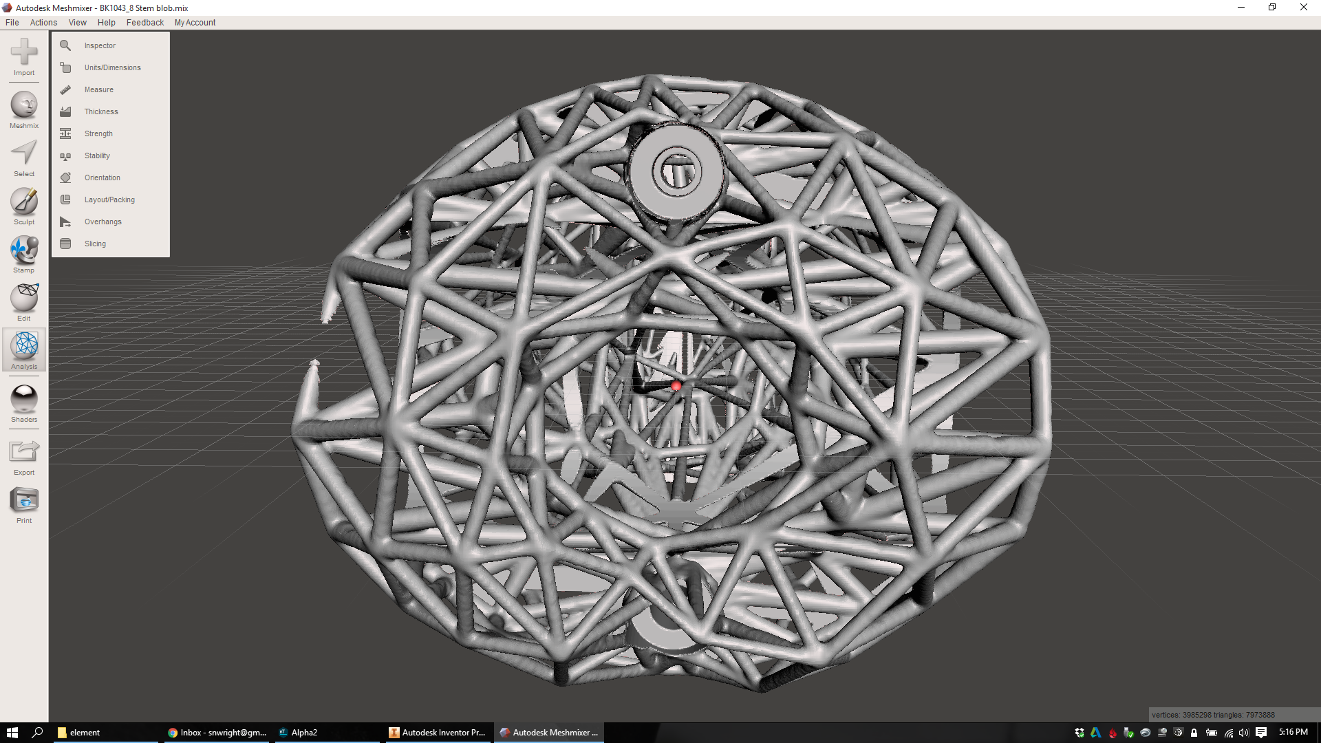
In subtractive manufacturing, any feature that's not a block of material is complex. That includes things like holes, threads, and bosses. It also includes high resolution (polished/ground) surfaces, complex (non Euclidian) geometries, and irregular 3D patterns.
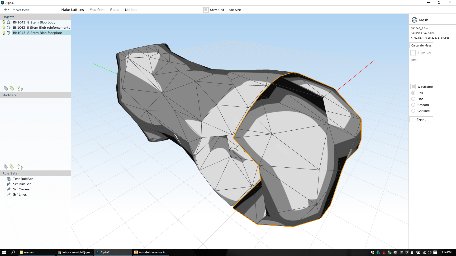
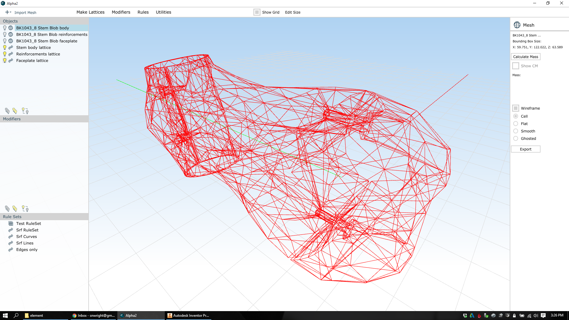
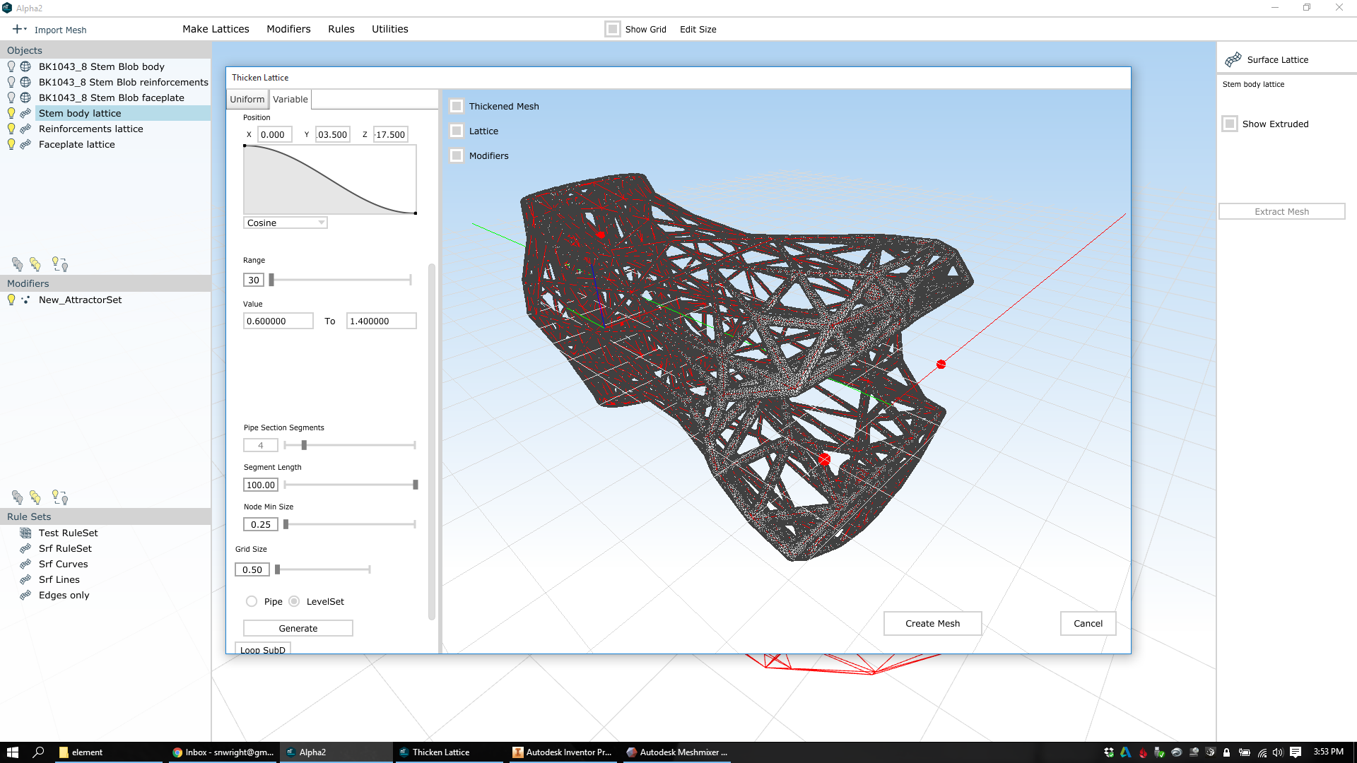
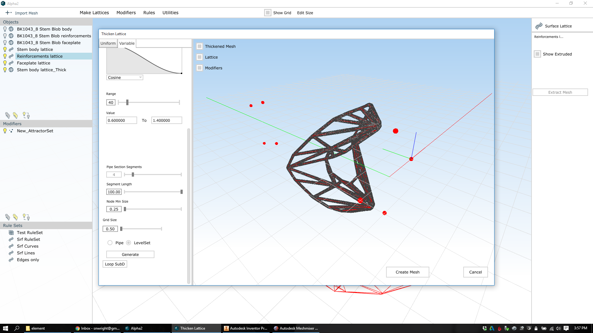
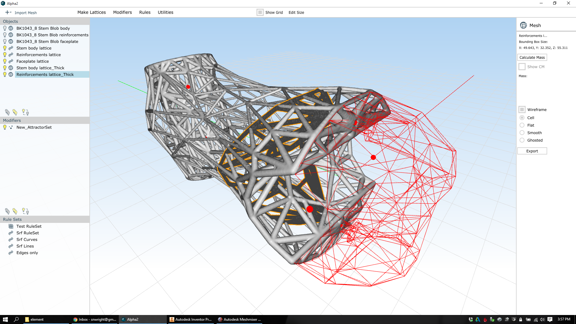
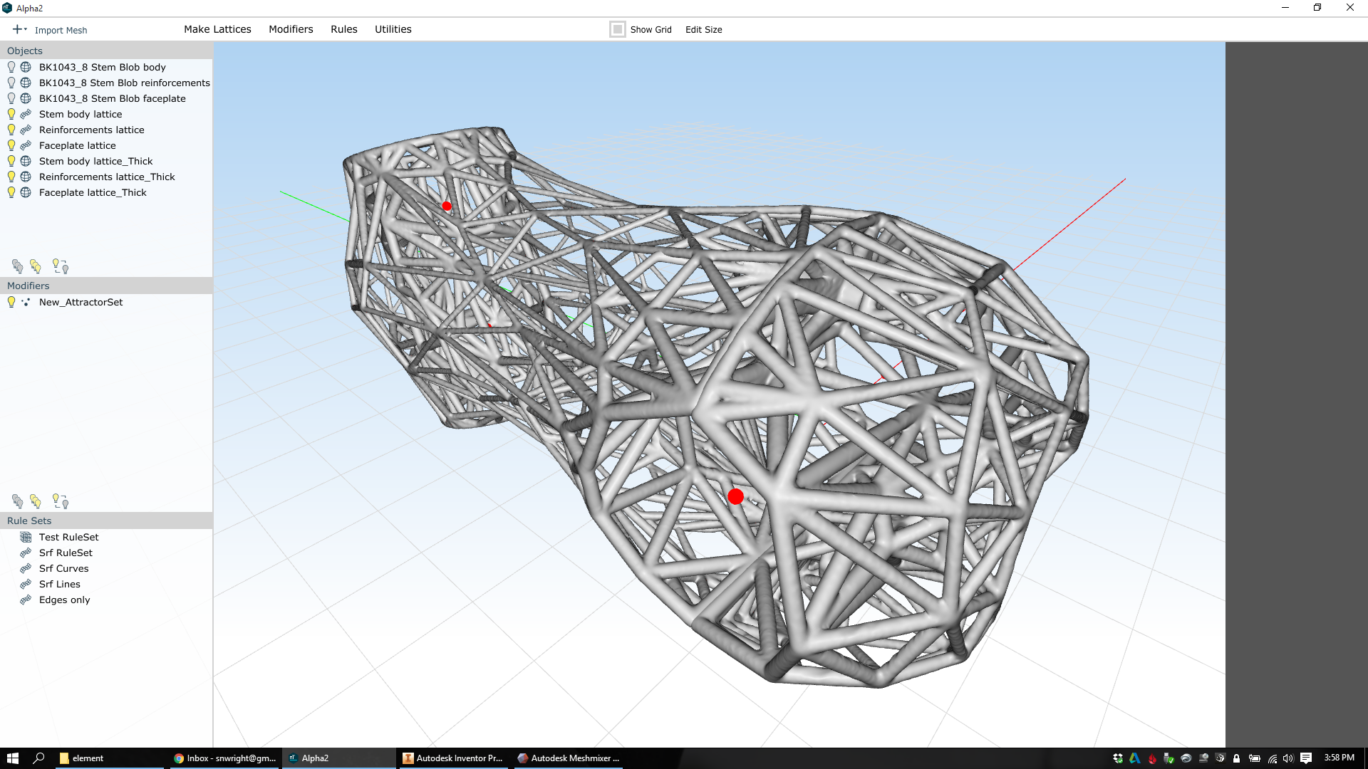
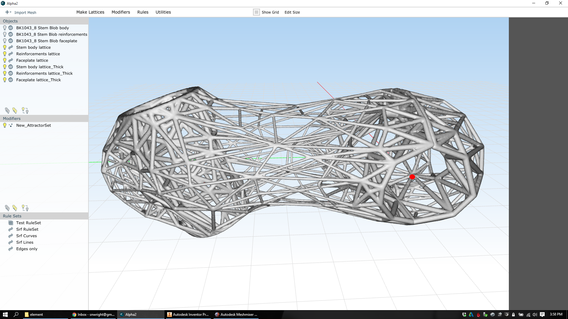
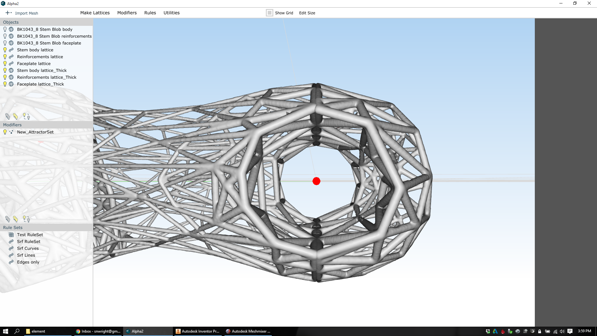
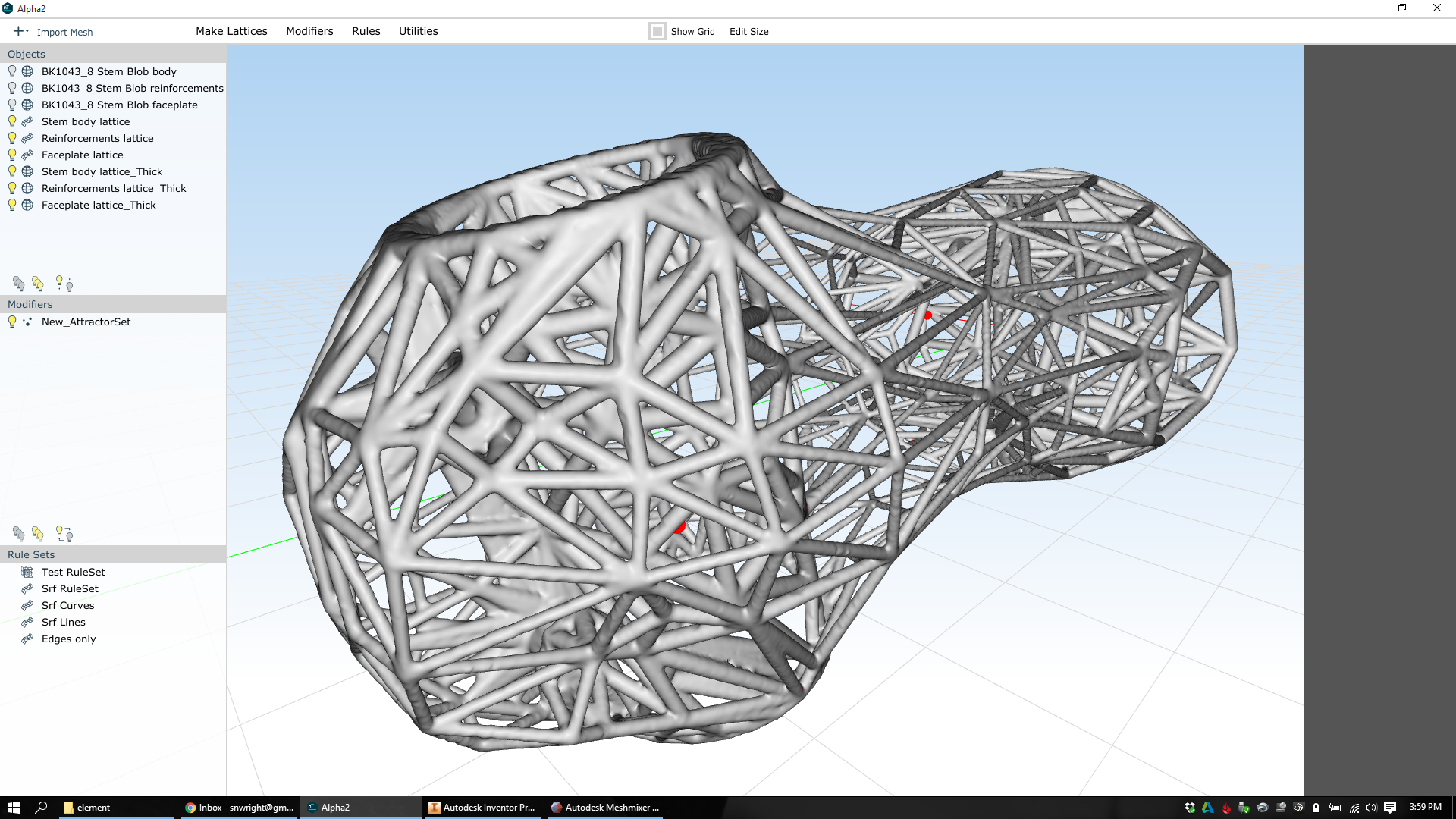
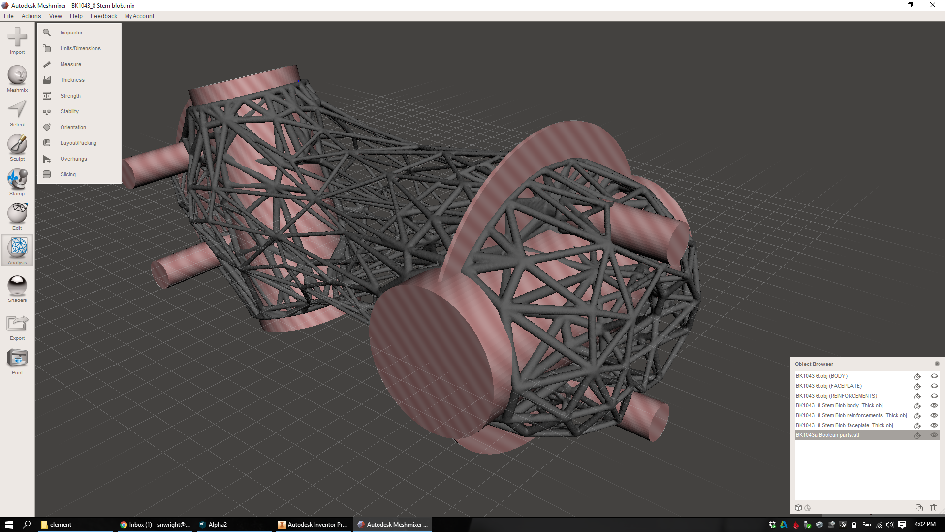
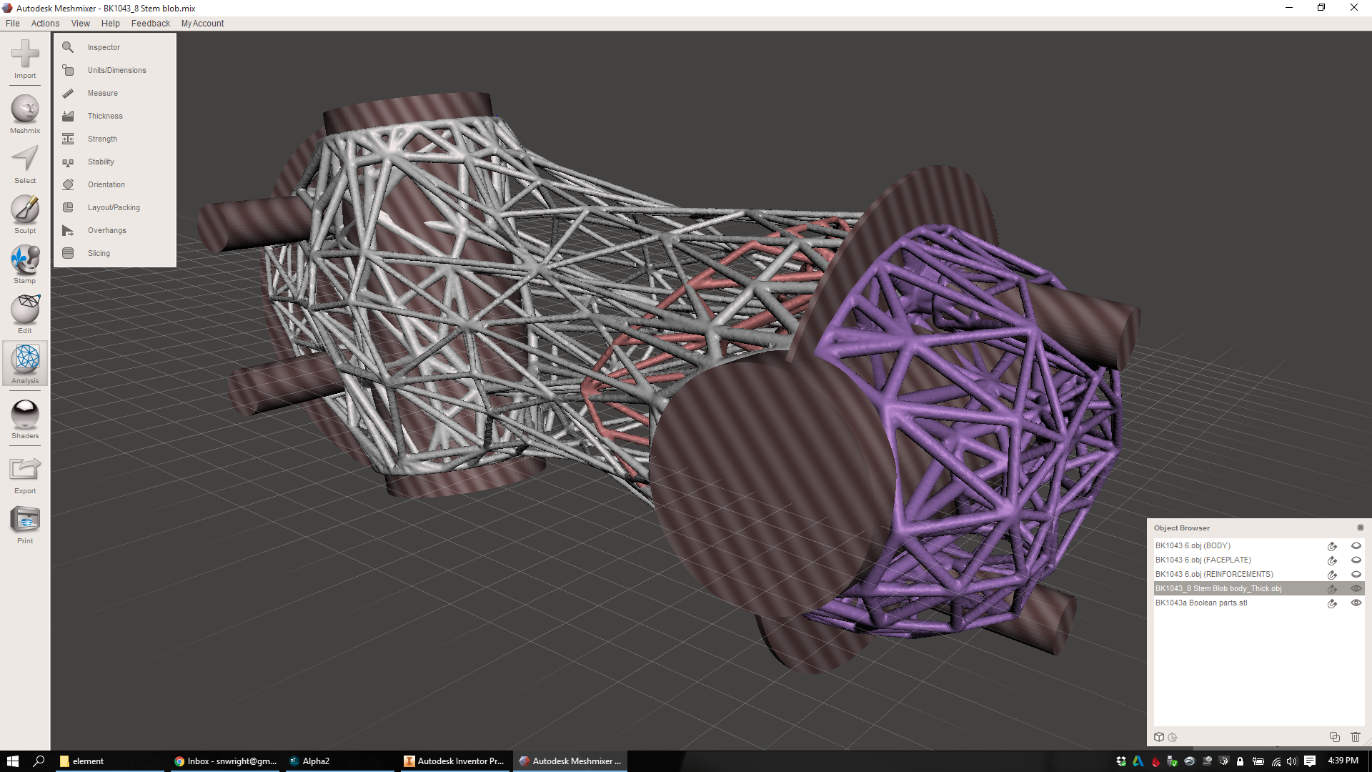
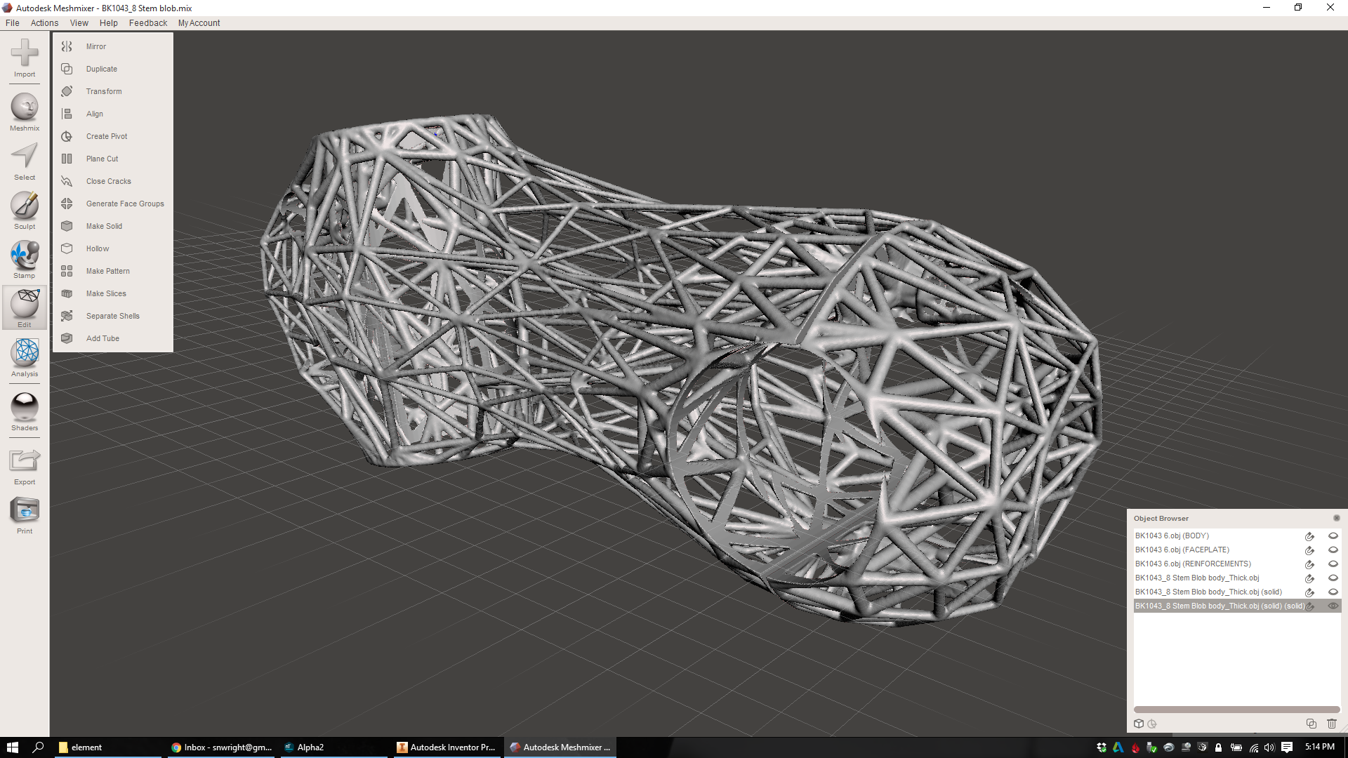
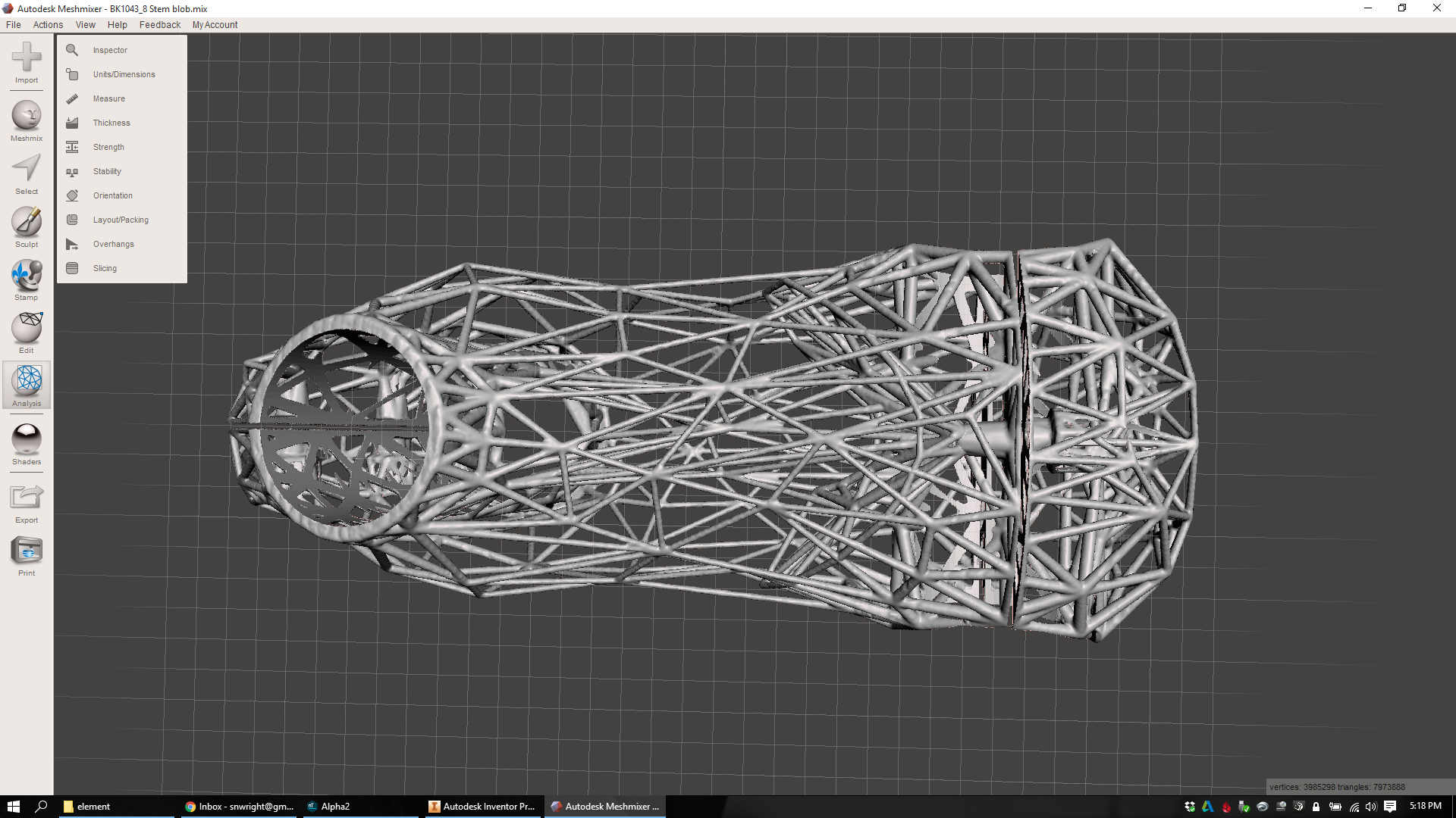
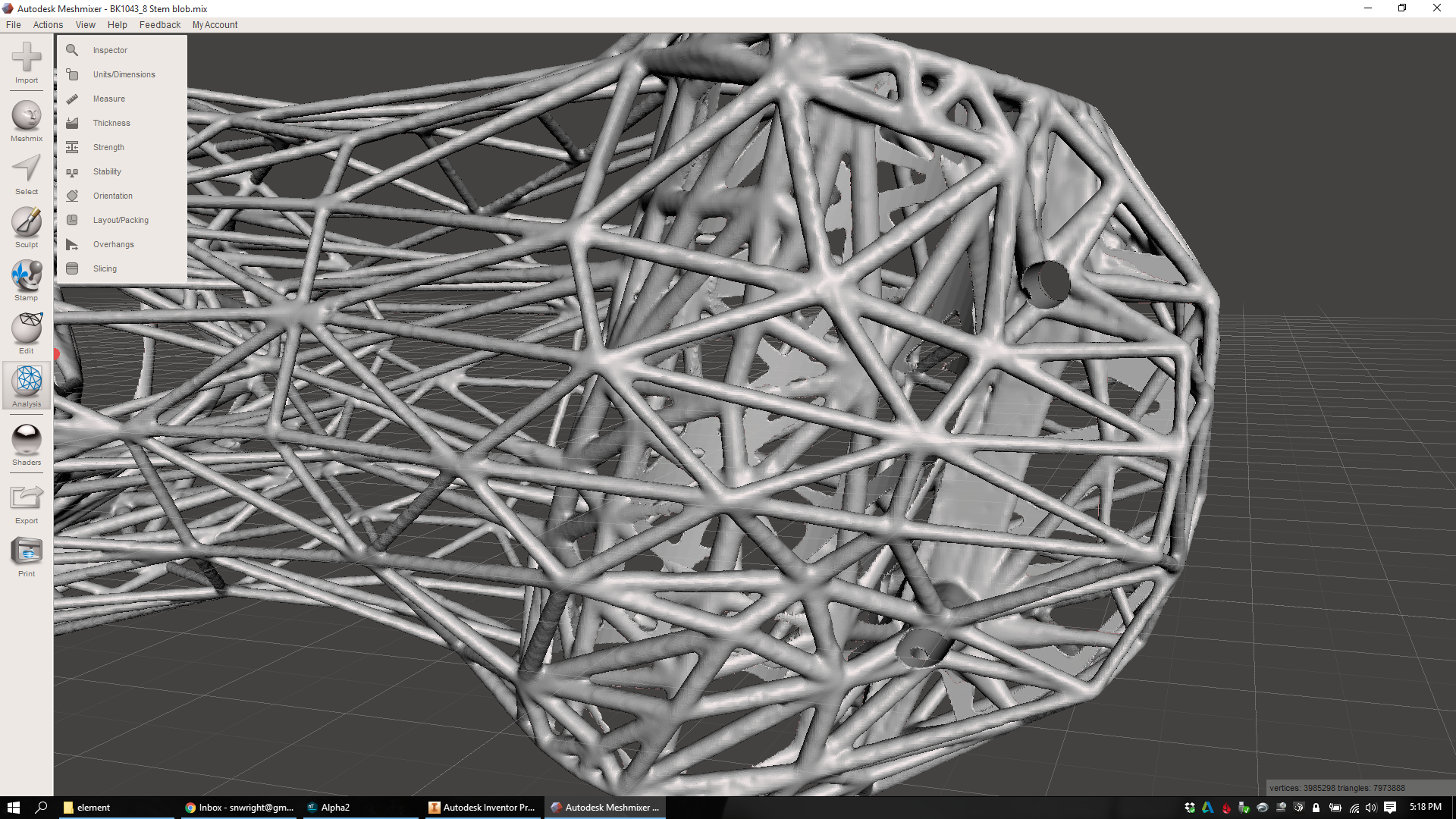
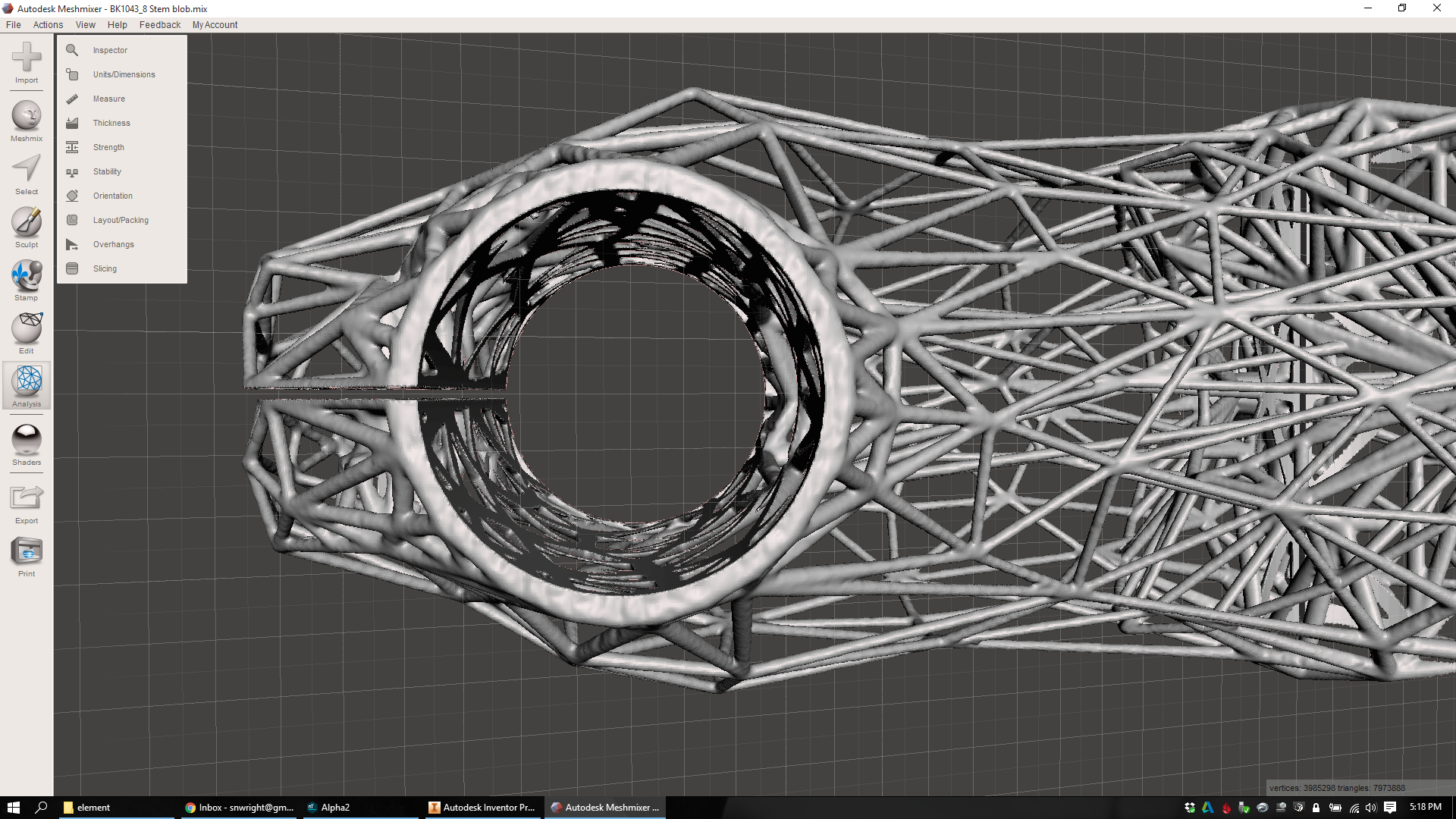
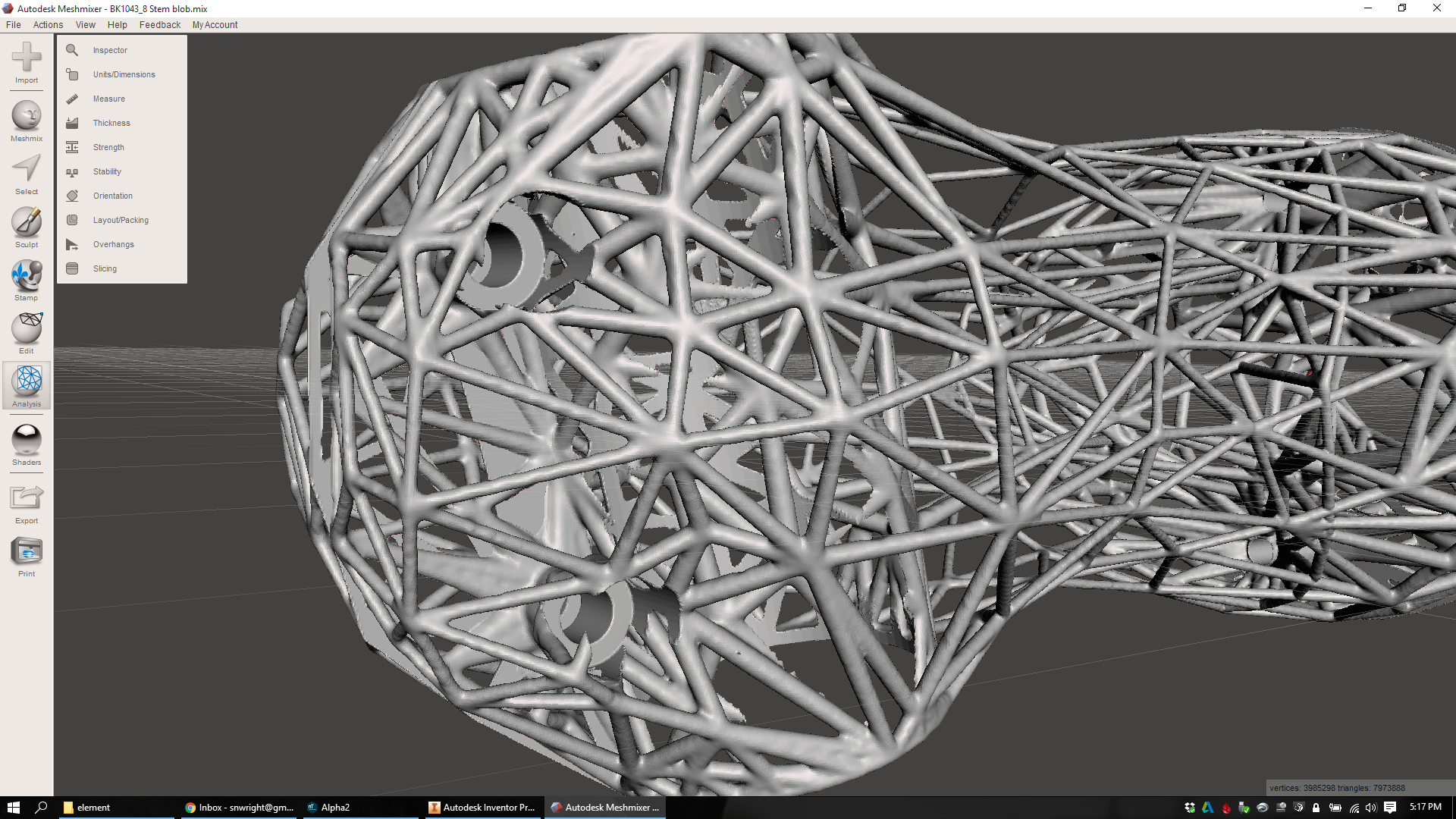
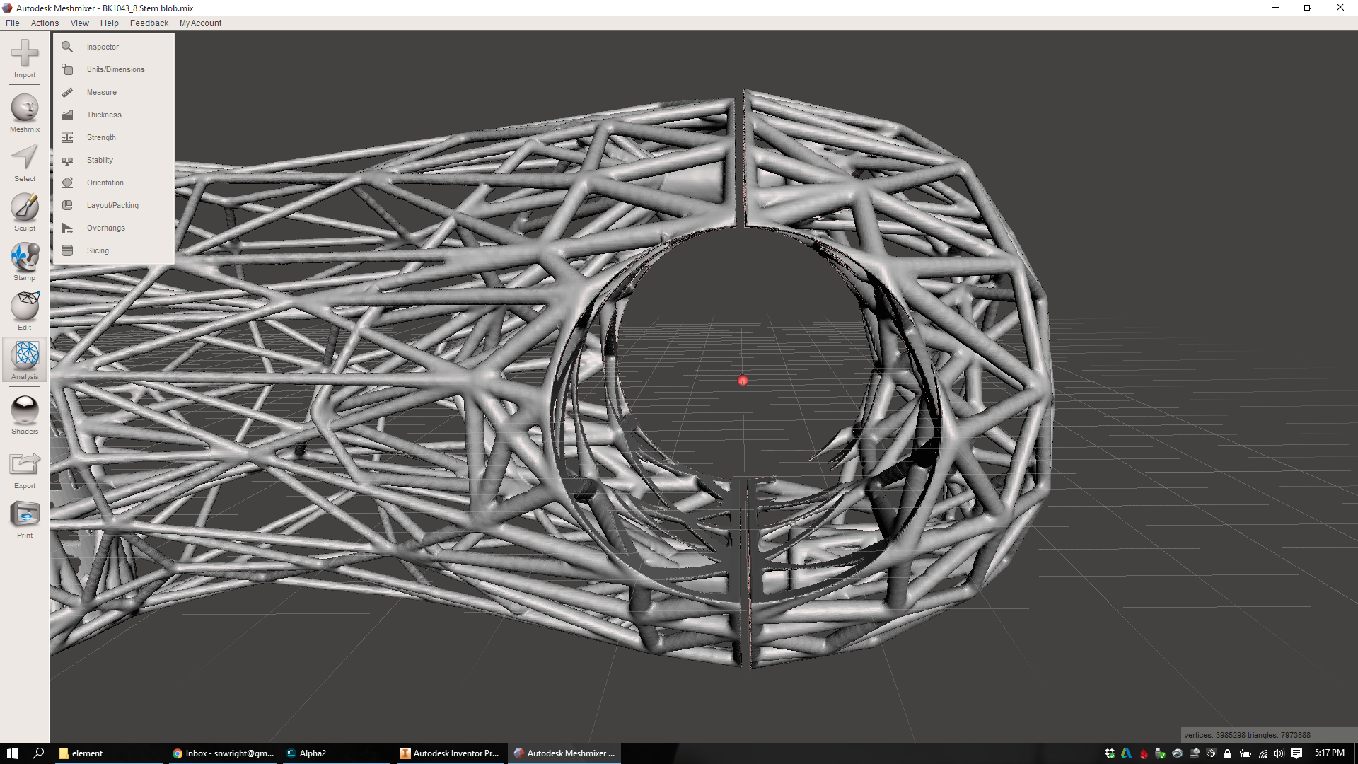
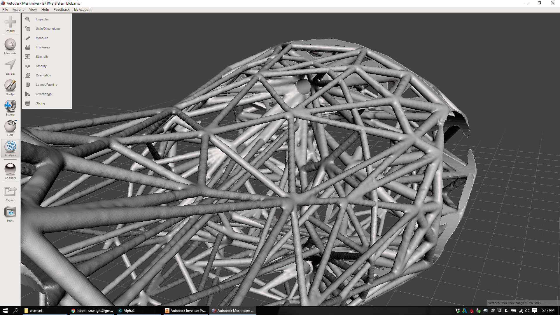
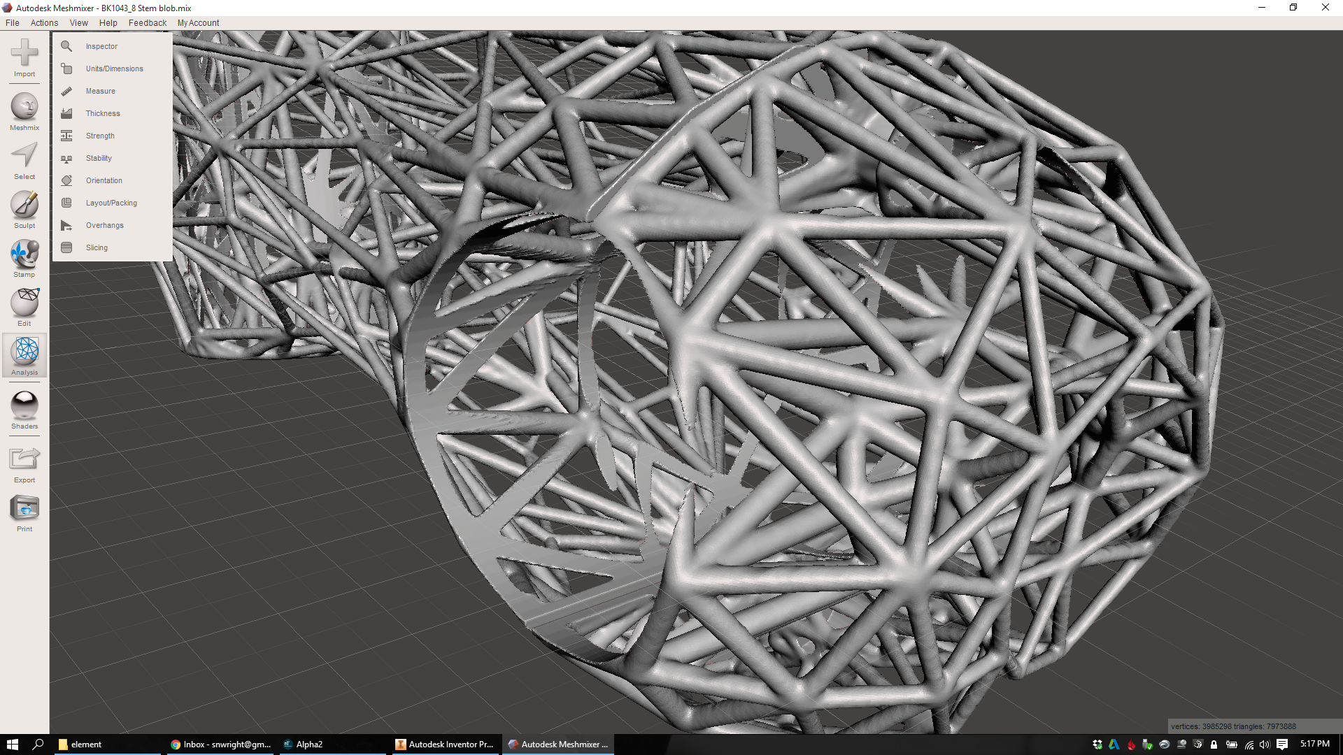
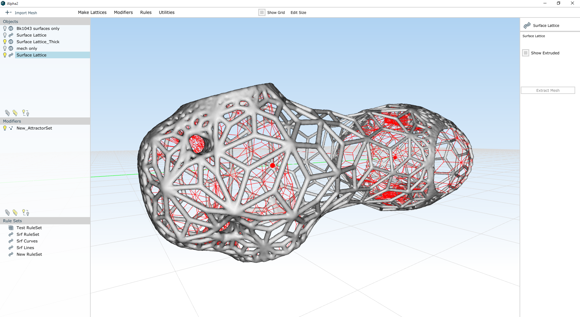
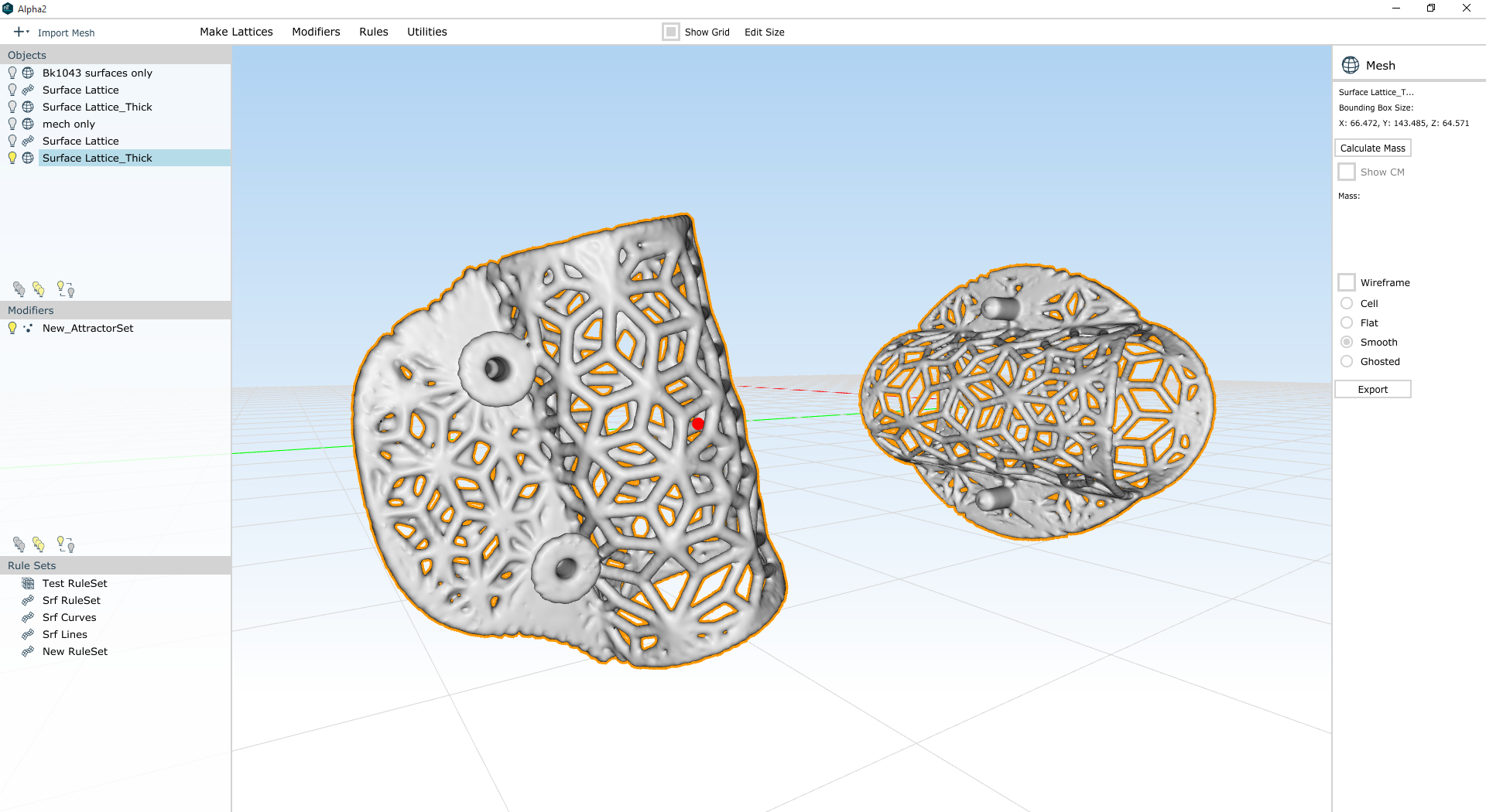
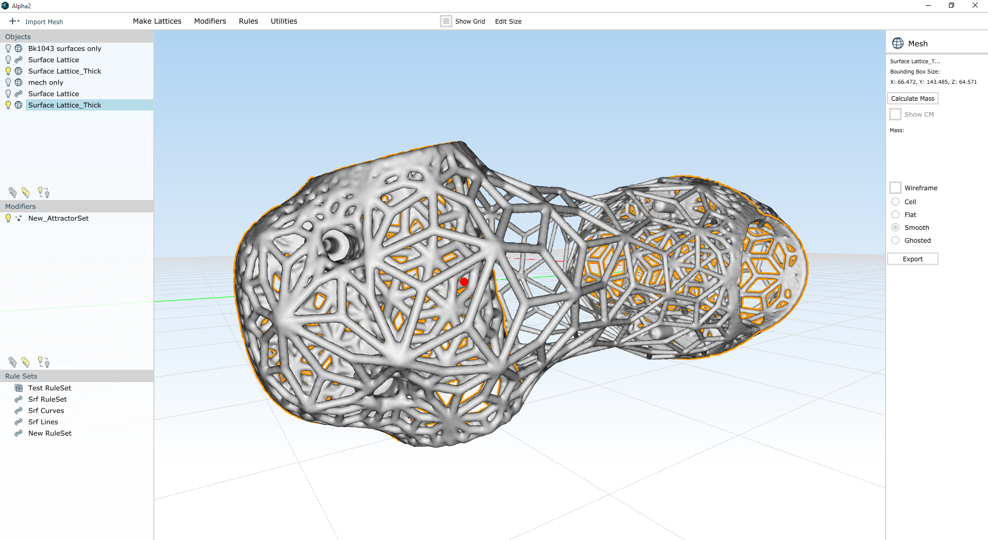
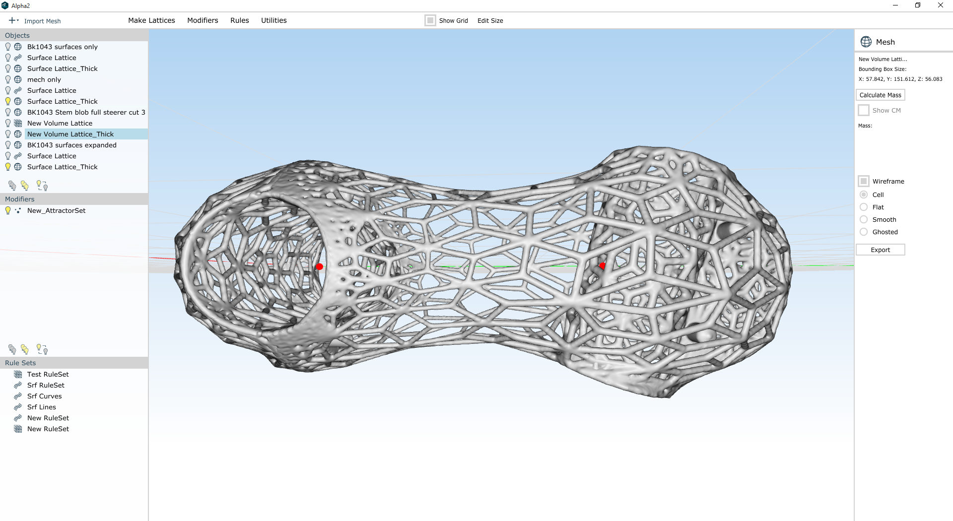
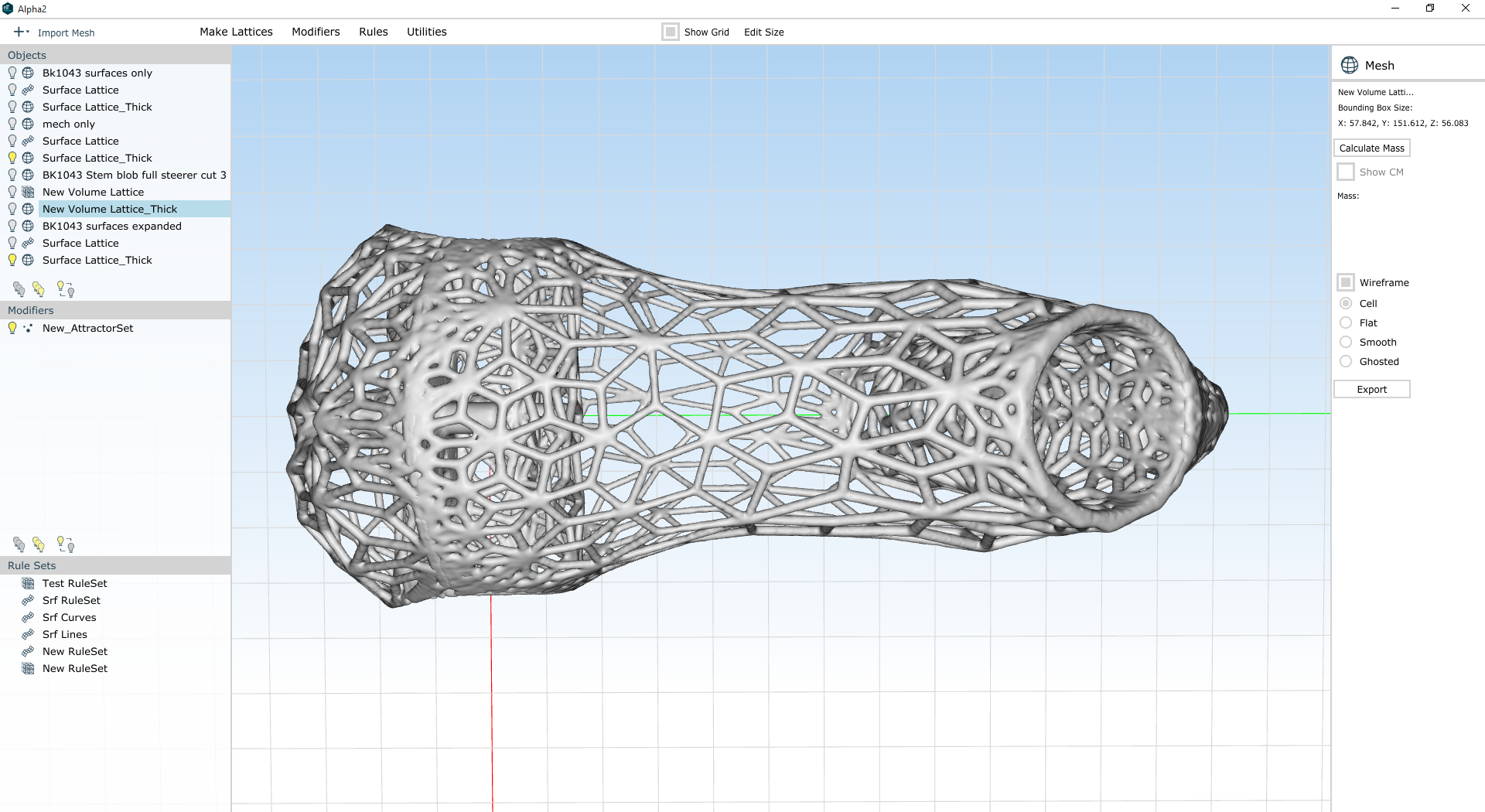
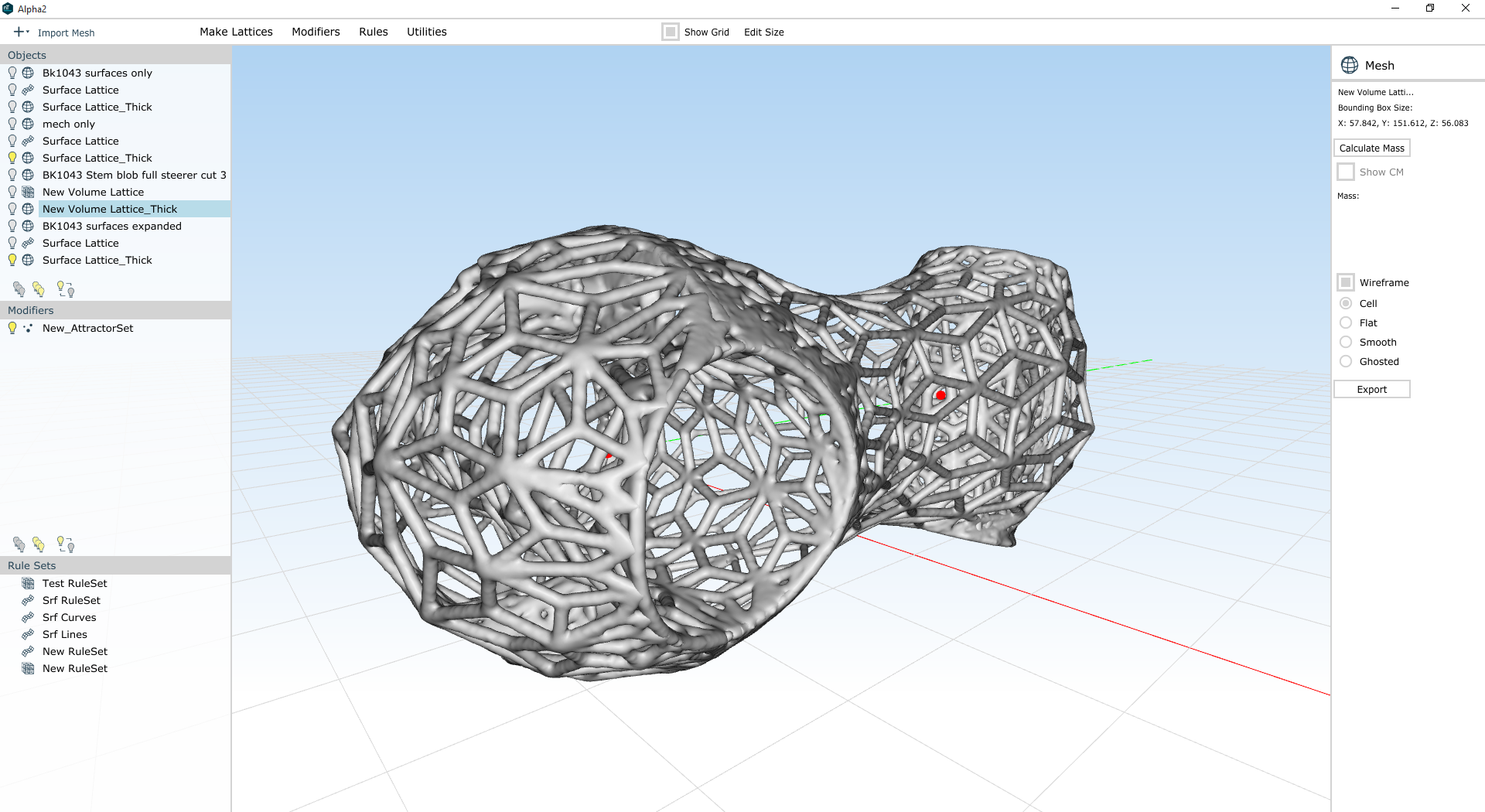
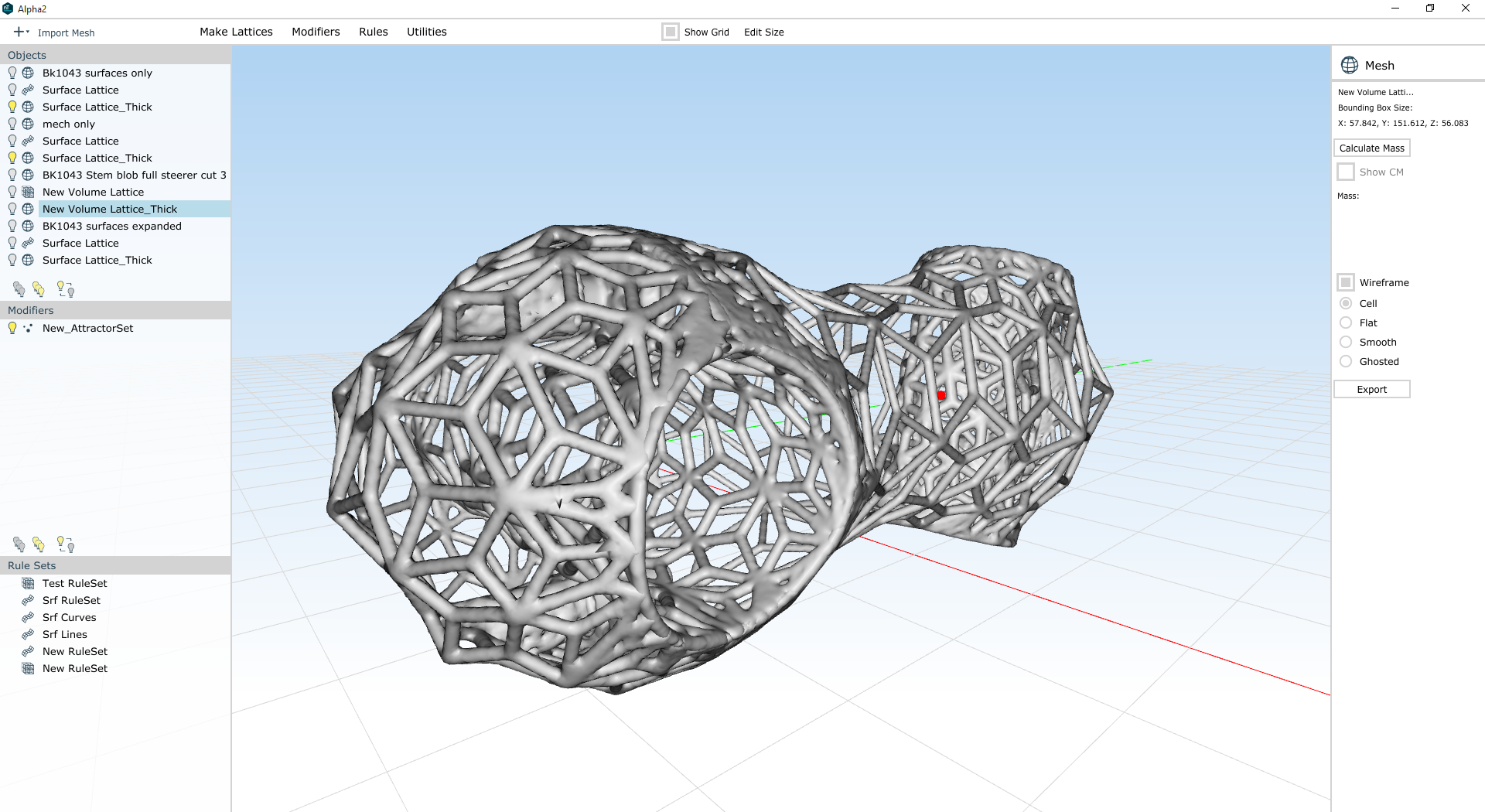
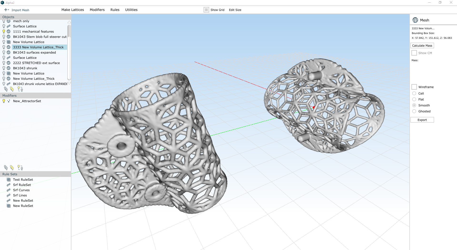
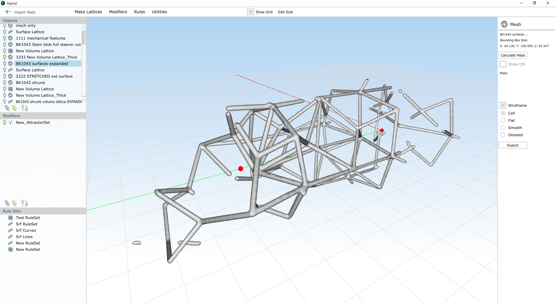
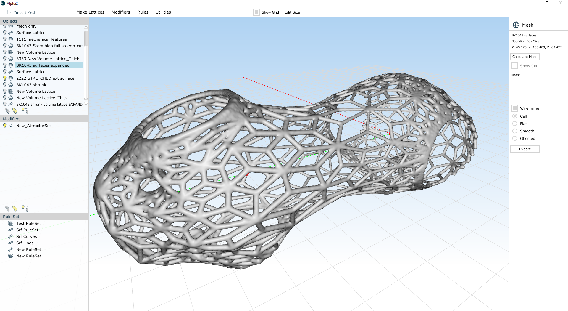
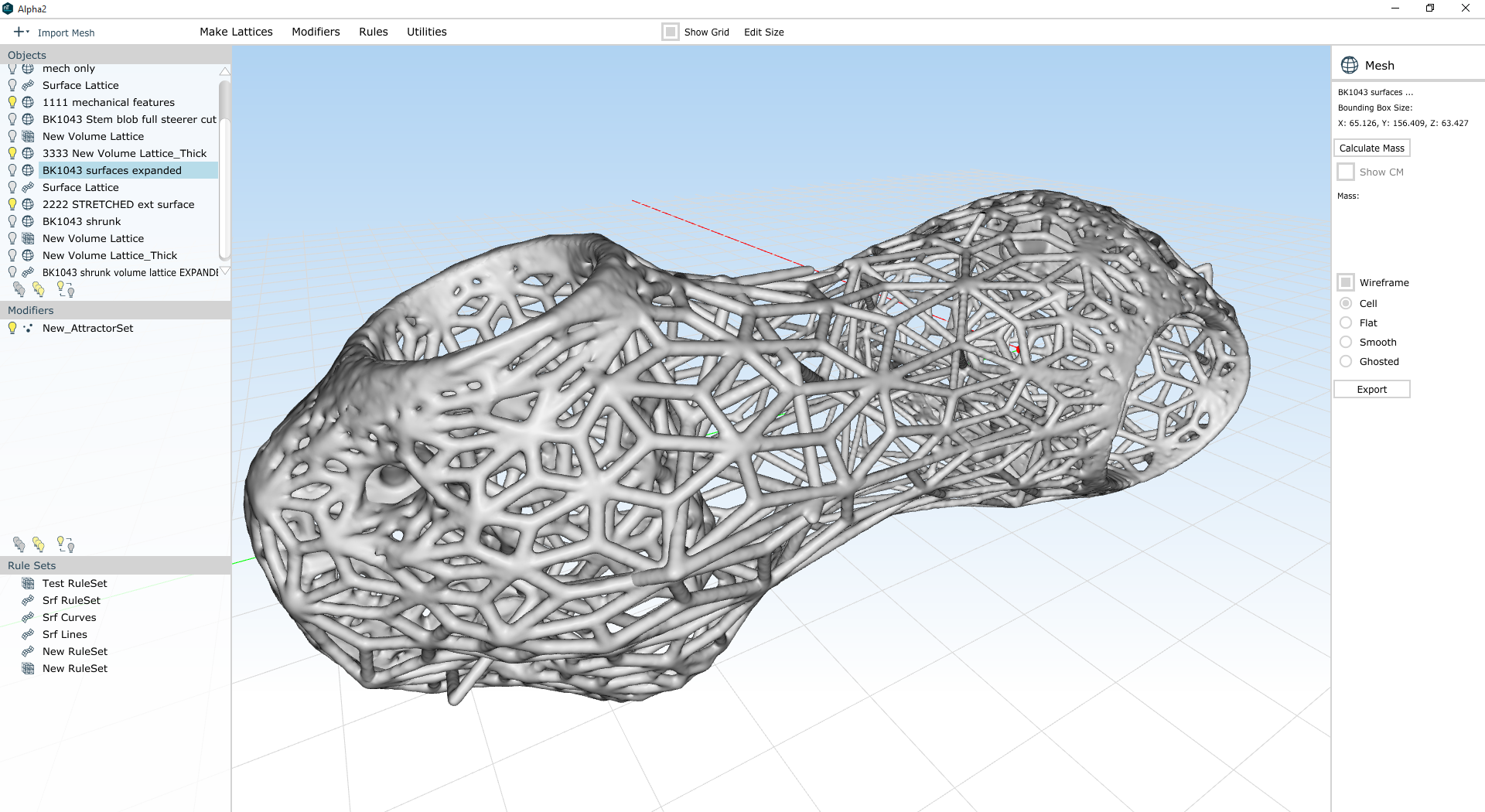
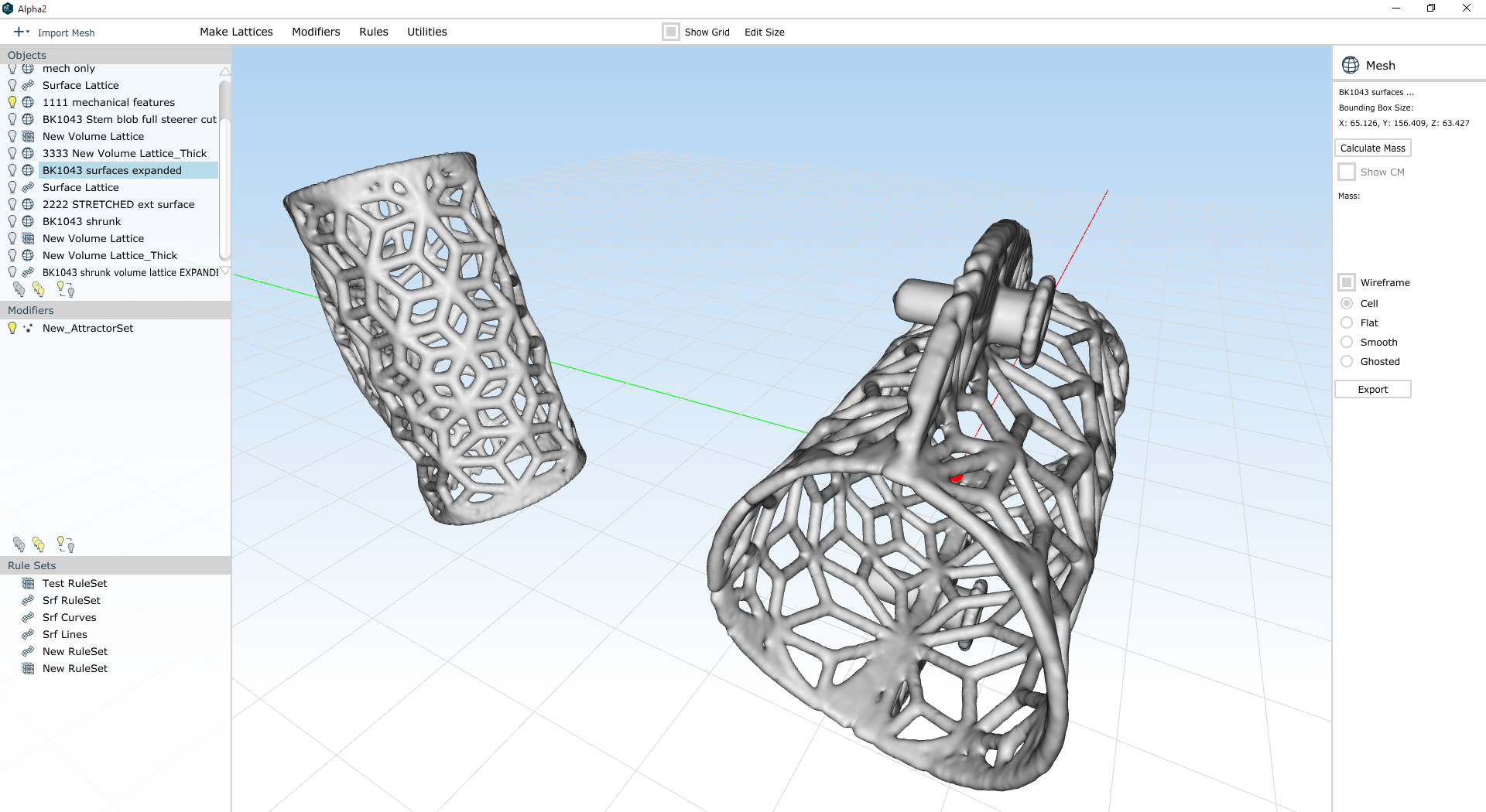
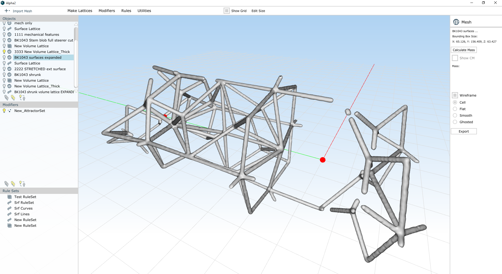
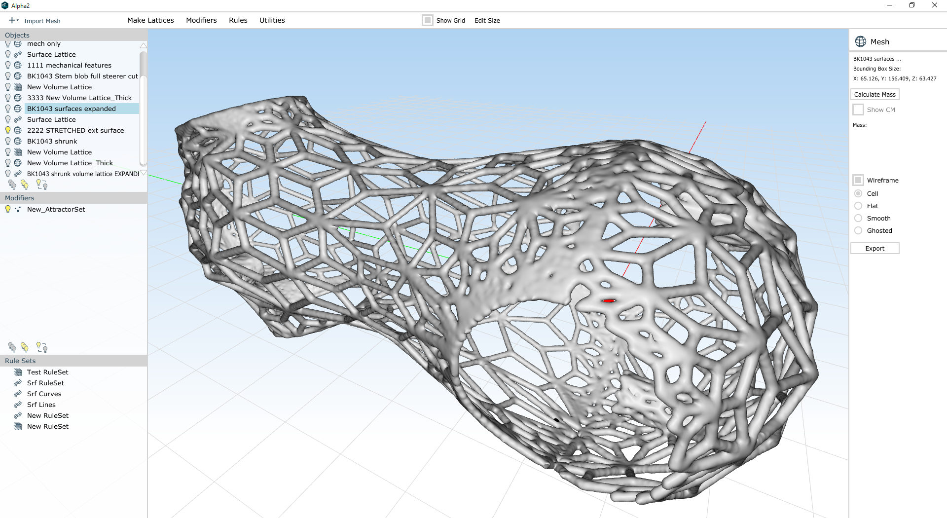
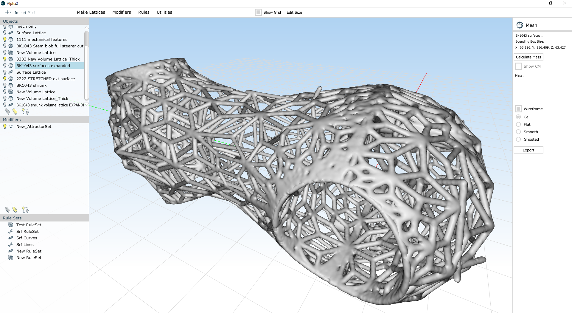
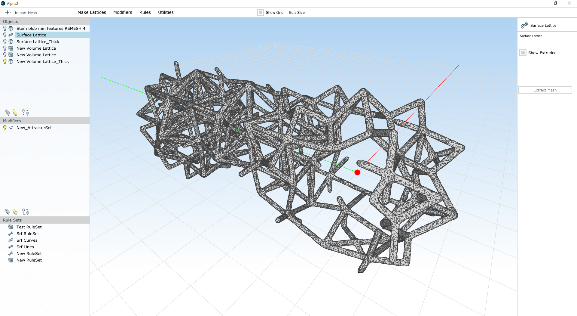
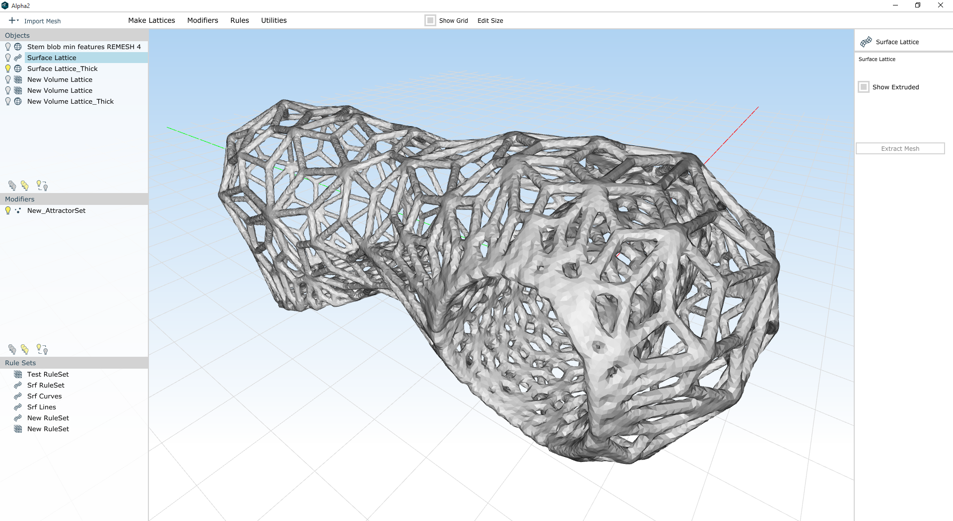
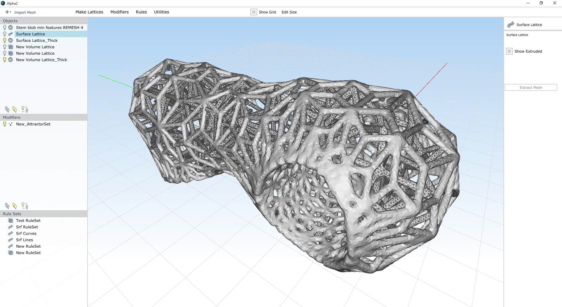
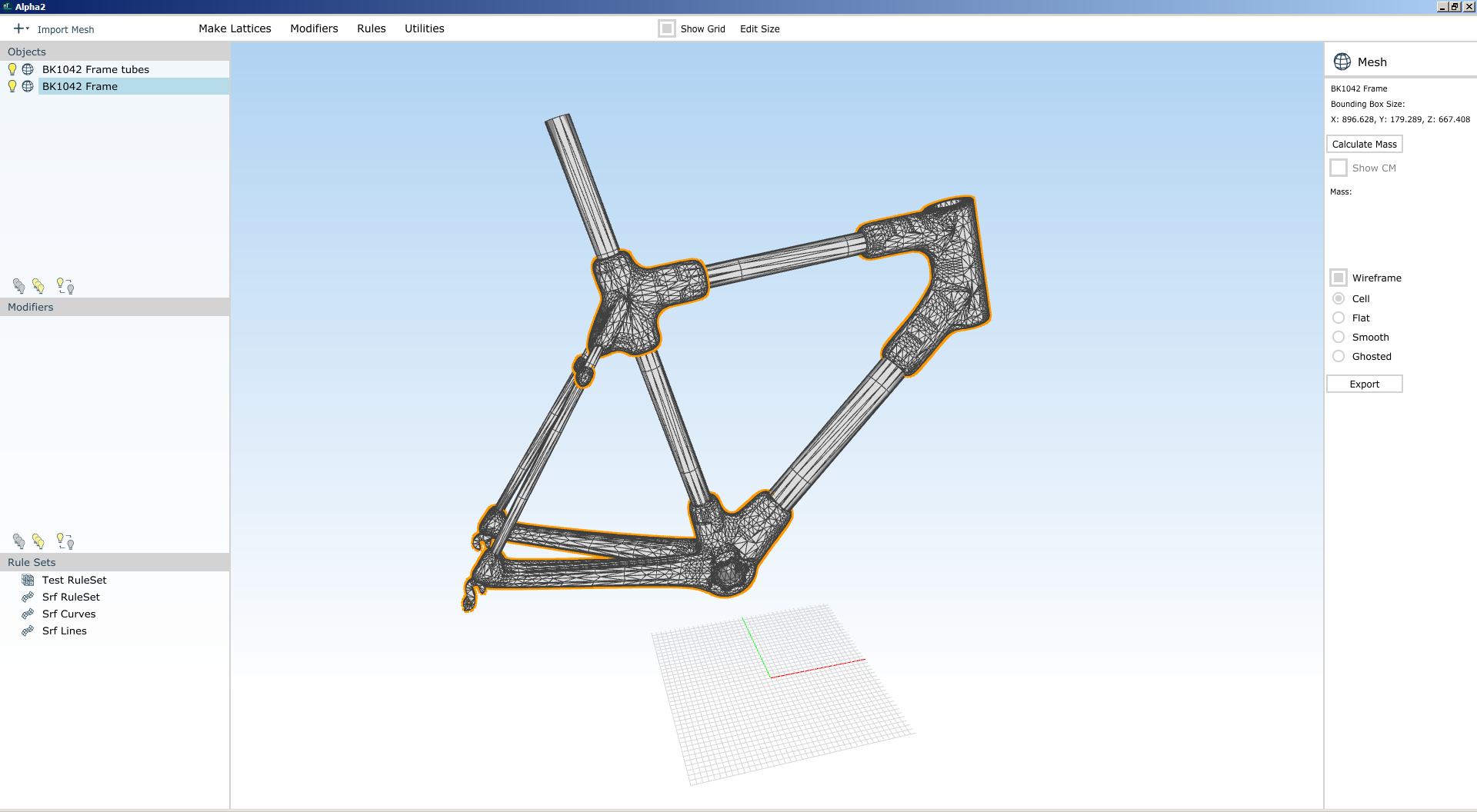
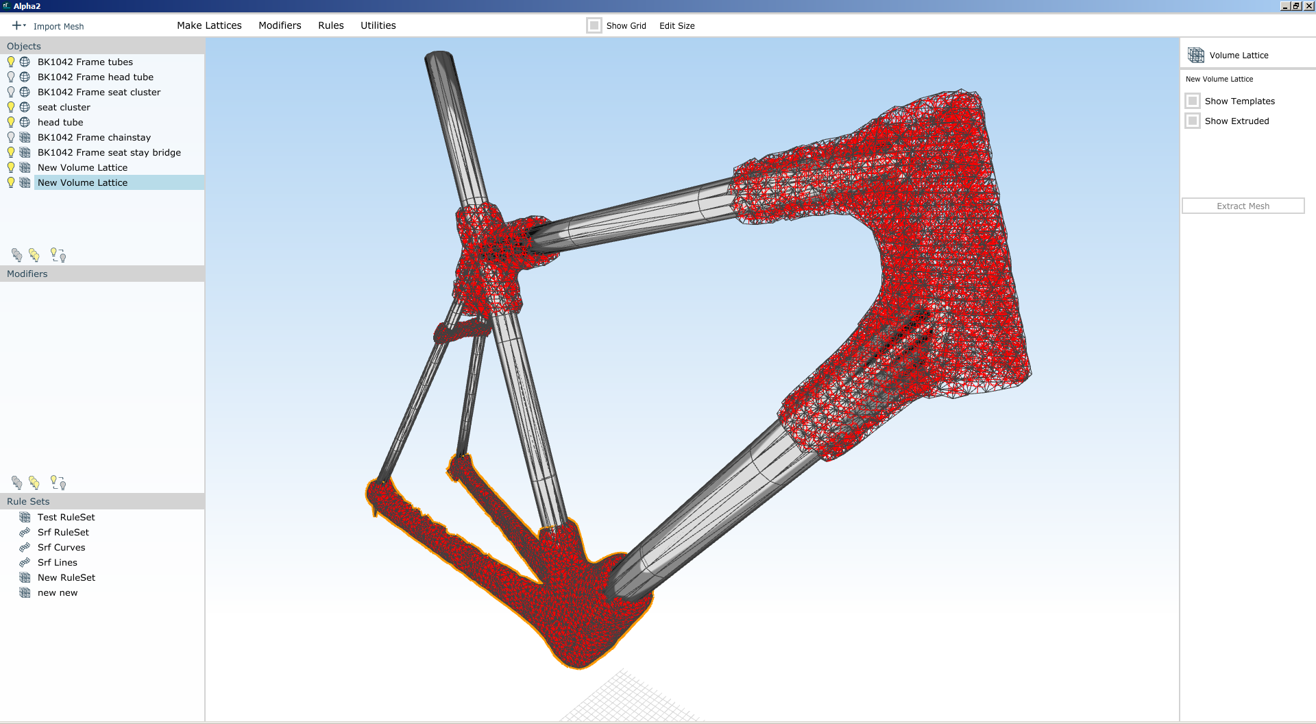
Many of these features are trivial to create by additive manufacturing. 3D lattice structures and compound curvature are a pain in the ass to mill out of a solid block, but in many cases they can be printed with little effort at all. This capability of 3D printing is - and this isn't hyperbole here - truly wonderful, and has no doubt spurred remarkable design innovation in the past few years.
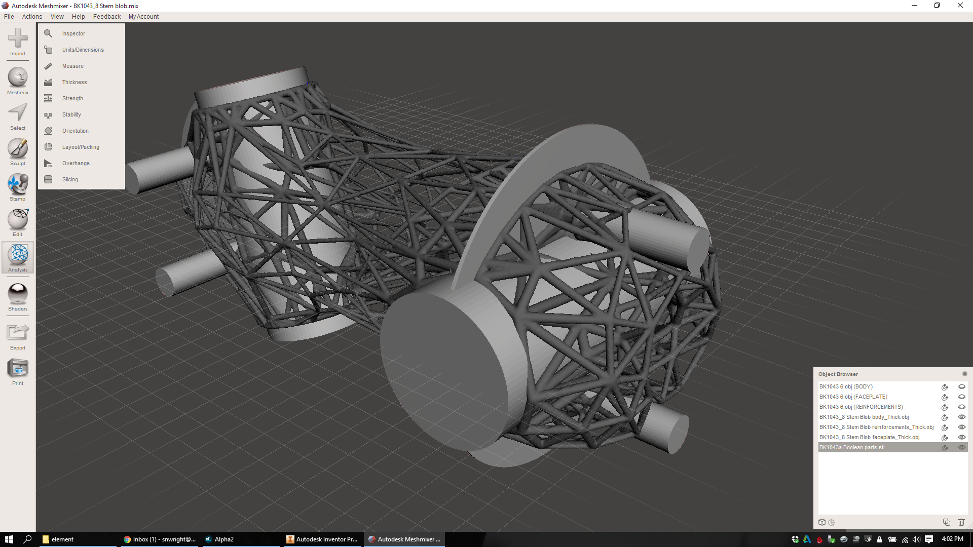
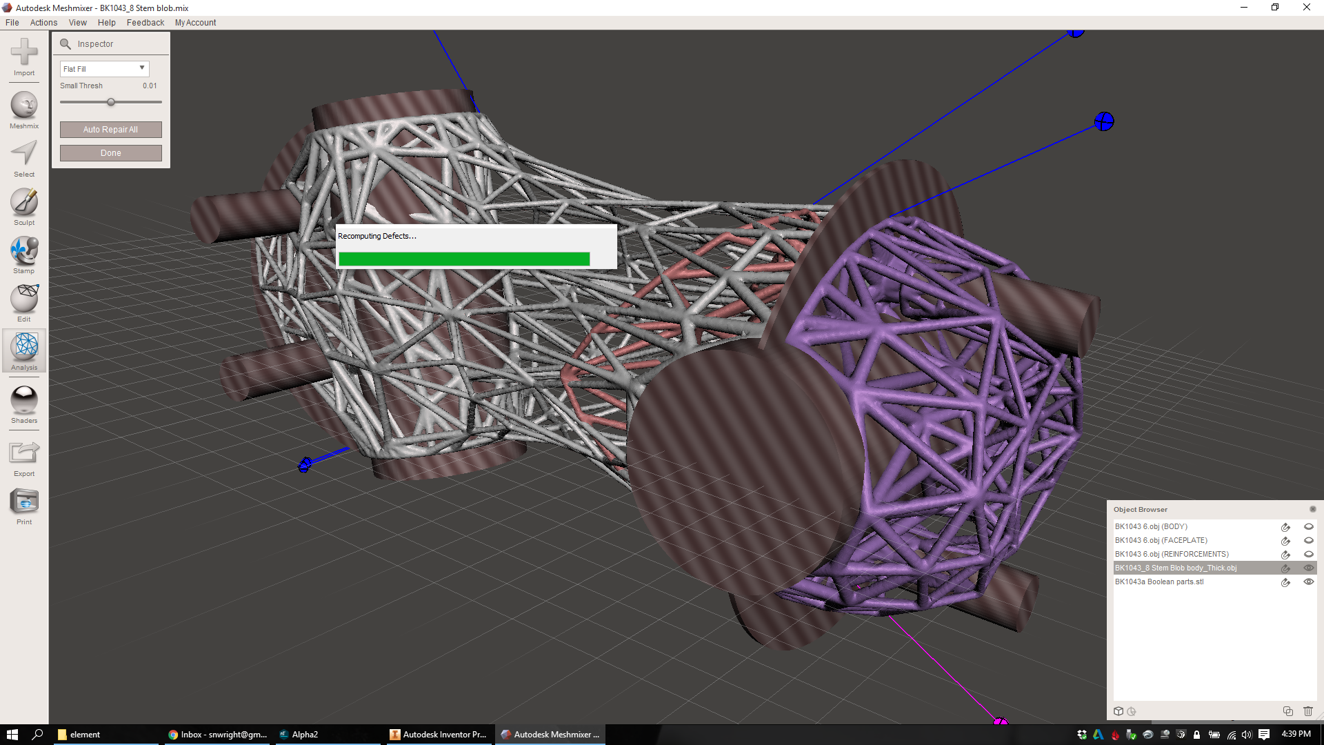
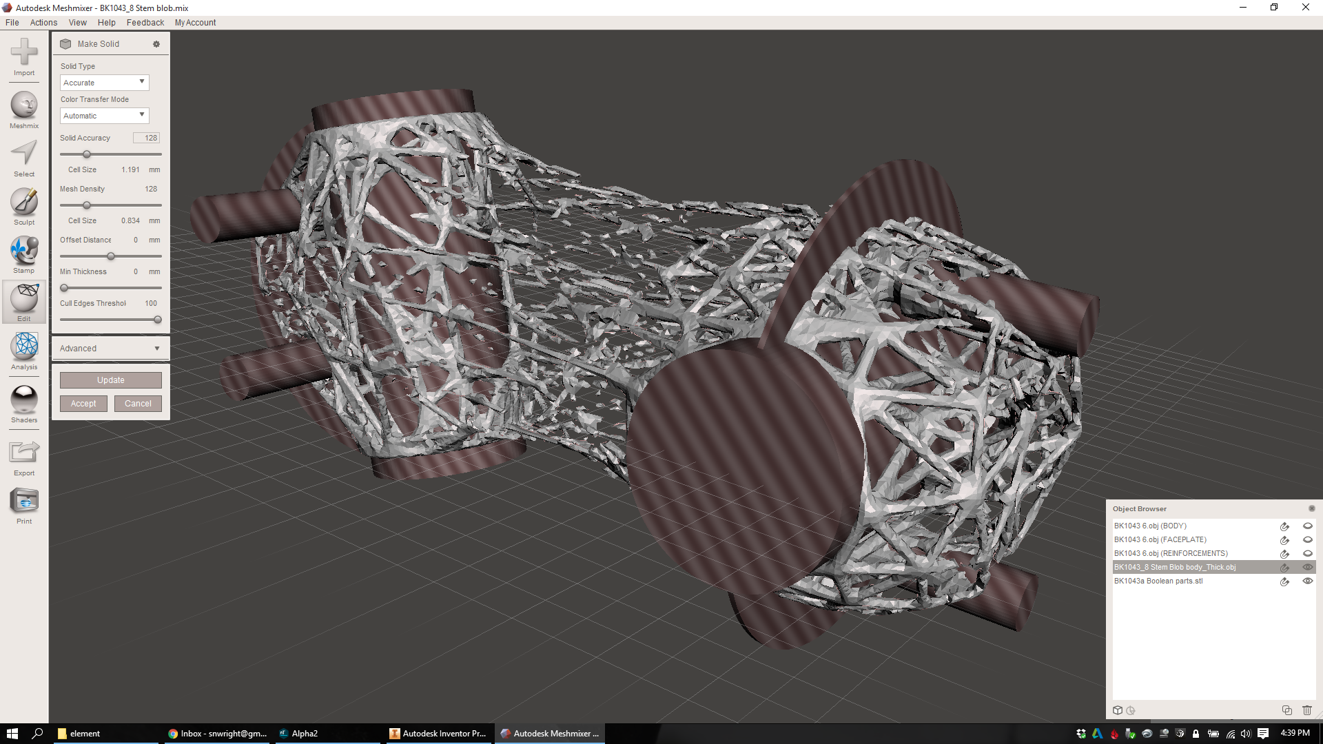
But that has nothing to do with the overall complexity of the design rules that apply to additive manufacturing. For instance: 3D printing is notably subject to interactions with gravity; overhanging faces are, with many technologies, extremely "complex" to produce. Surface finish is a constant issue, requiring huge efforts in both actual post-processing time AND the intellectual effort required to develop a cost effective and logistically simple supply chain for the finished part. And the crystalline and thermal interactions occurring within metal AM are, to a great extent, barely understood at all - while with subtractive, the process is repeatable and mature.
These variables - things like surface finish, orientation to the build plate, and metallurgy - make additive manufacturing immensely complex. Anyone who tells you otherwise is pulling your leg.
What these people mean to say, I think, is that the design rules for additive manufacturing are drastically different from the design rules for subtractive & formative manufacturing. Which they absolutely are. And, to be totally clear, this is part of what I love about AM - the chance to rethink the basic assumptions that I've always taken towards conventional product development. But it's *not* a reduction in manufacturing or design complexity - and I think the sales pitch for additive is hurt when these two things are conflated.
Optimization is relative.
Here, I'd like to use an analogy:
Adobe Photoshop is a tool for creating visual designs for humans to look at.
Photoshop has a number of features, but the end result of all of them is to change the colors of the pixels on your screen. Each of those pixels has a brightness and a hue, and hue boils down to the wavelength of the light that each pixel is emitting. Human eyes, meanwhile, respond to light with wavelengths from about 390 to 700 nm.
There are some exceptions, but we're pretty good at engineering computer monitors so that they produce light within the visible spectrum. When I go into Photoshop and draw a line, it'll let me color that line in red, or purple, or anywhere in between. There are some cases where the palette falls short, but in general it's able to produce every color that I'd ever want to see - and none that I can't. If you ask a graphic designer to draw an ultraviolet or infrared line in Photoshop, they'll look at you like you're crazy.
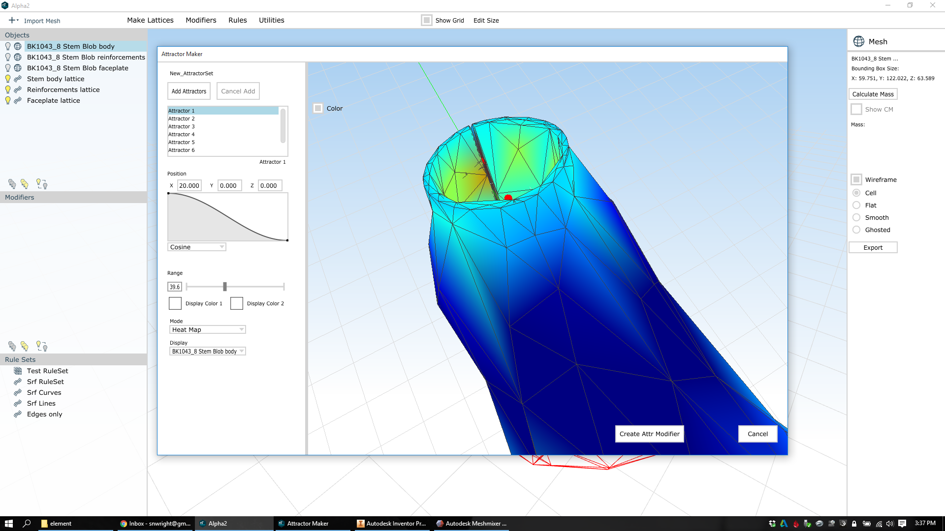
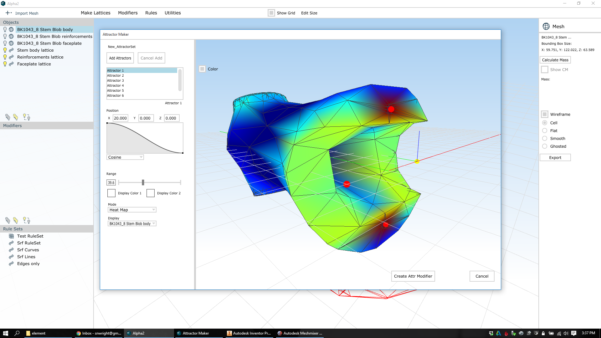
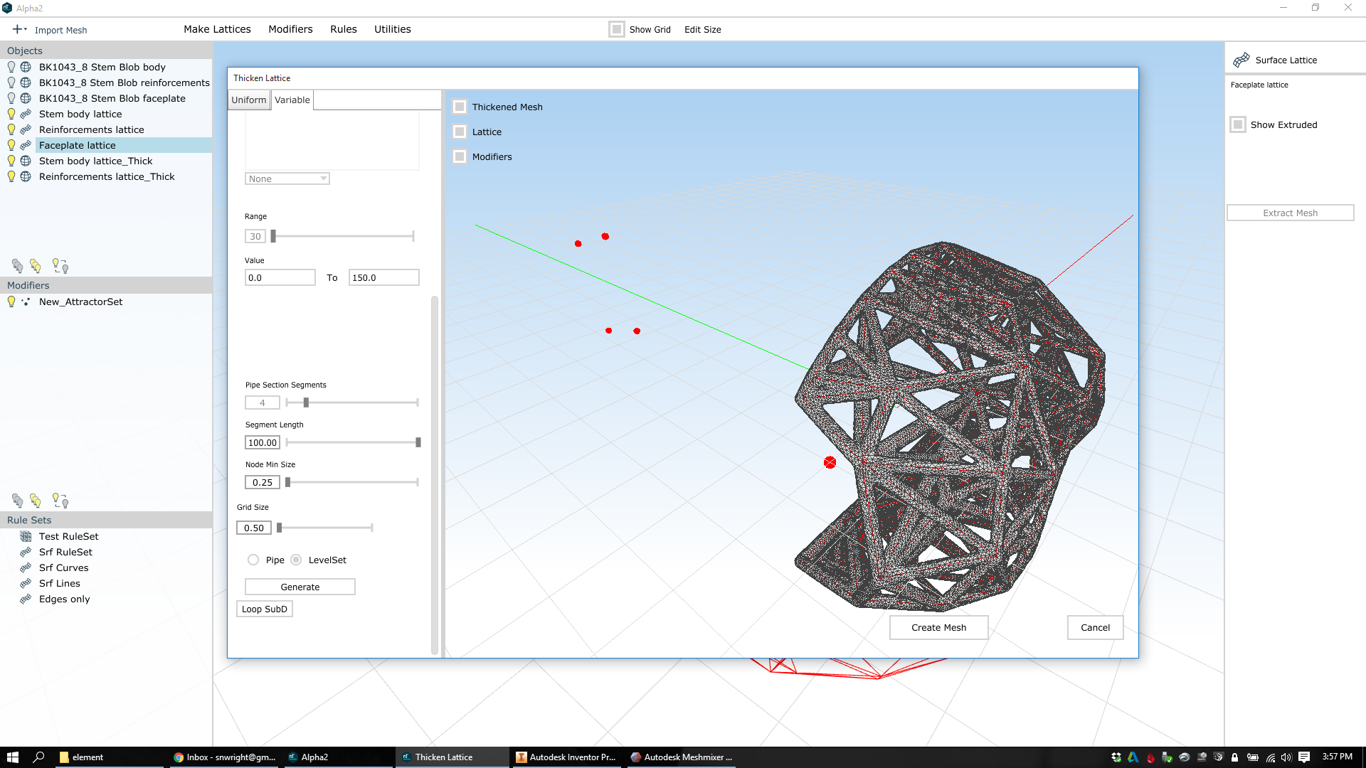
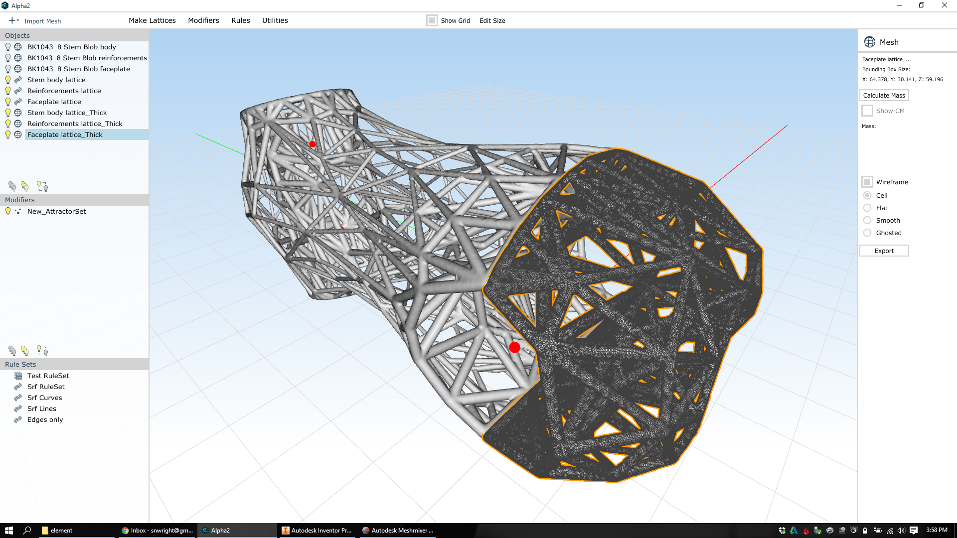
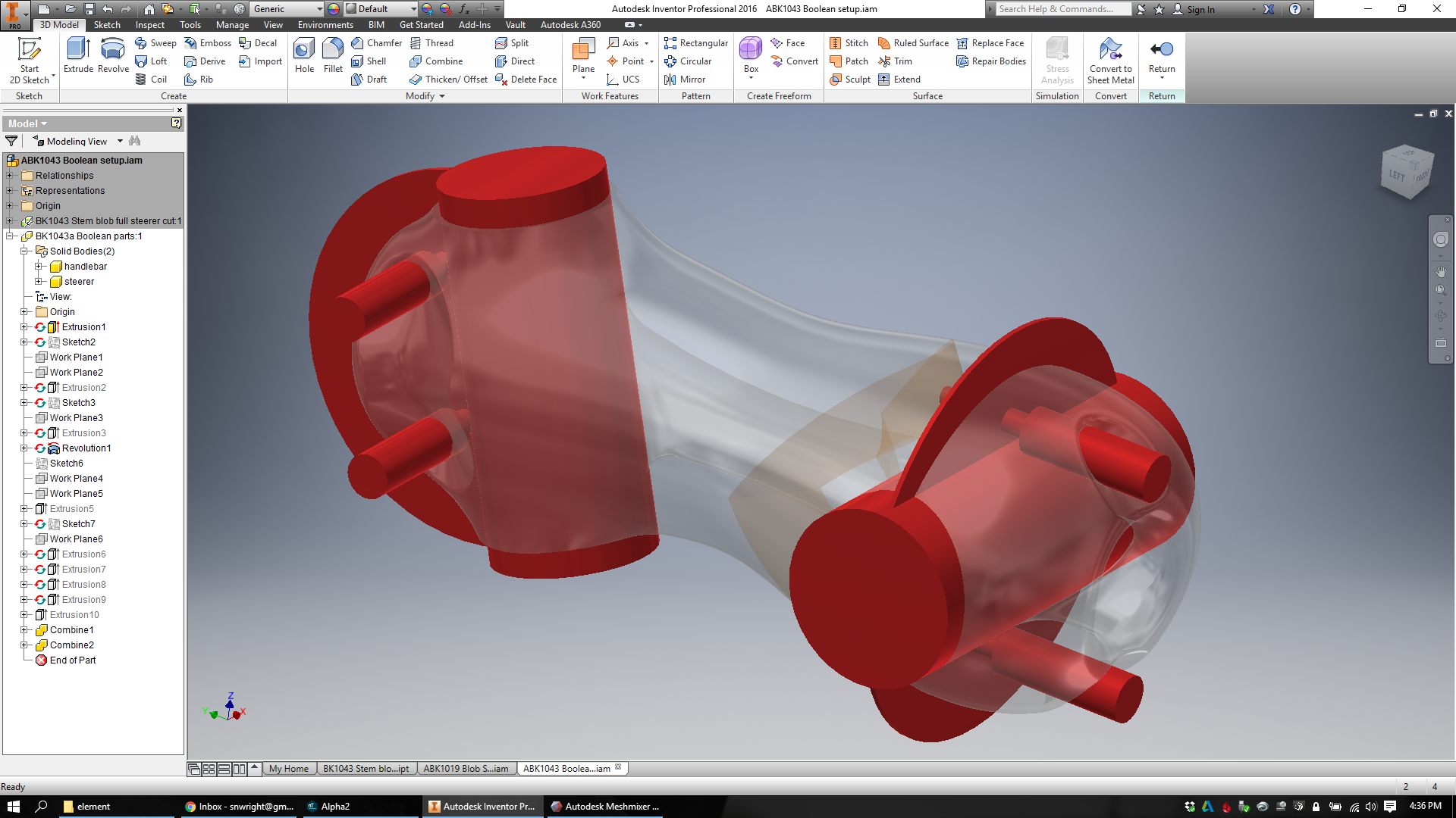
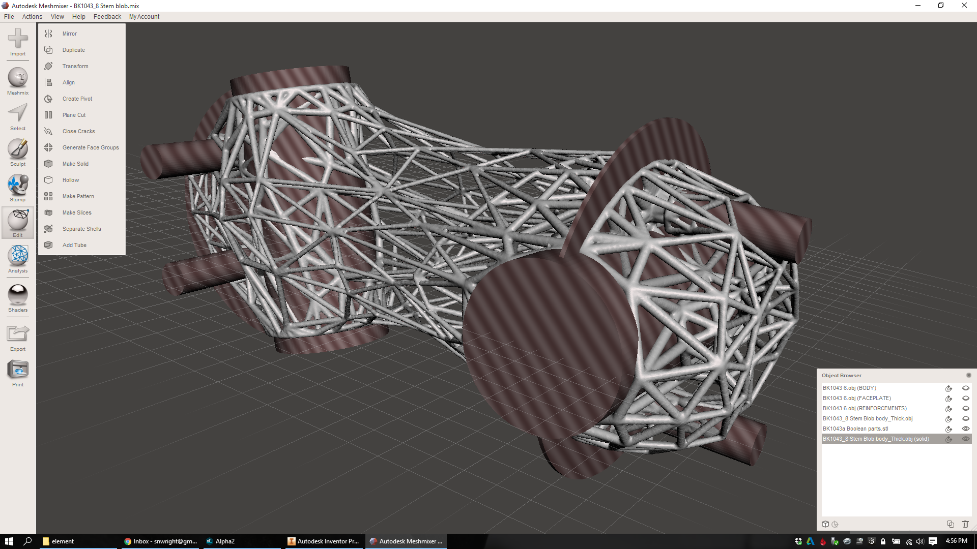
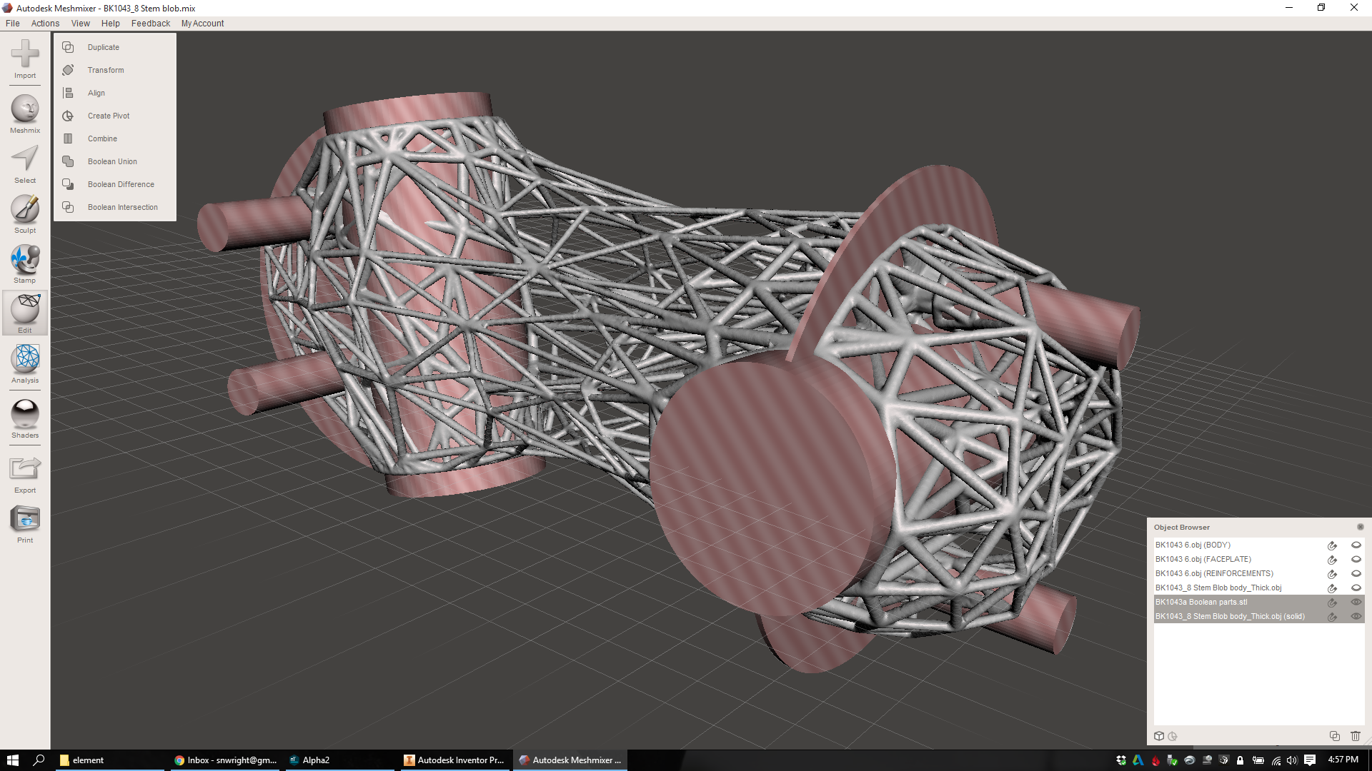
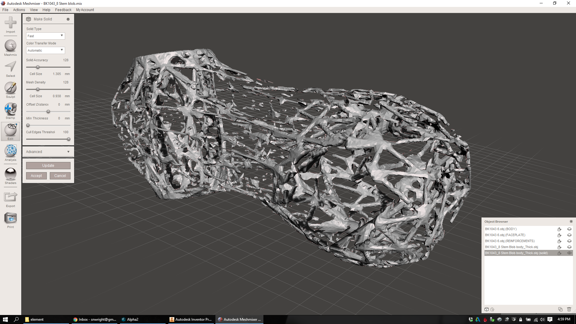
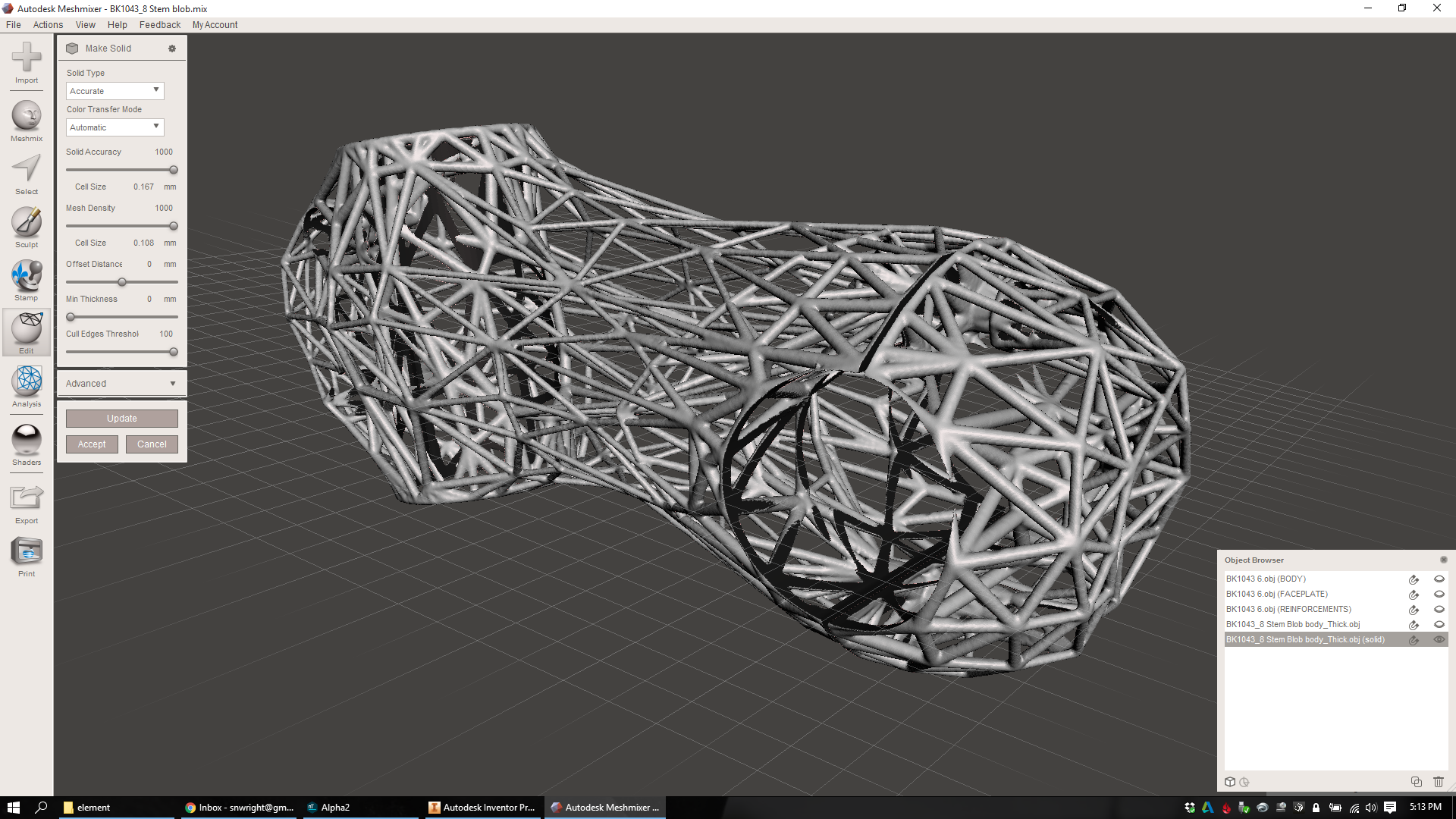
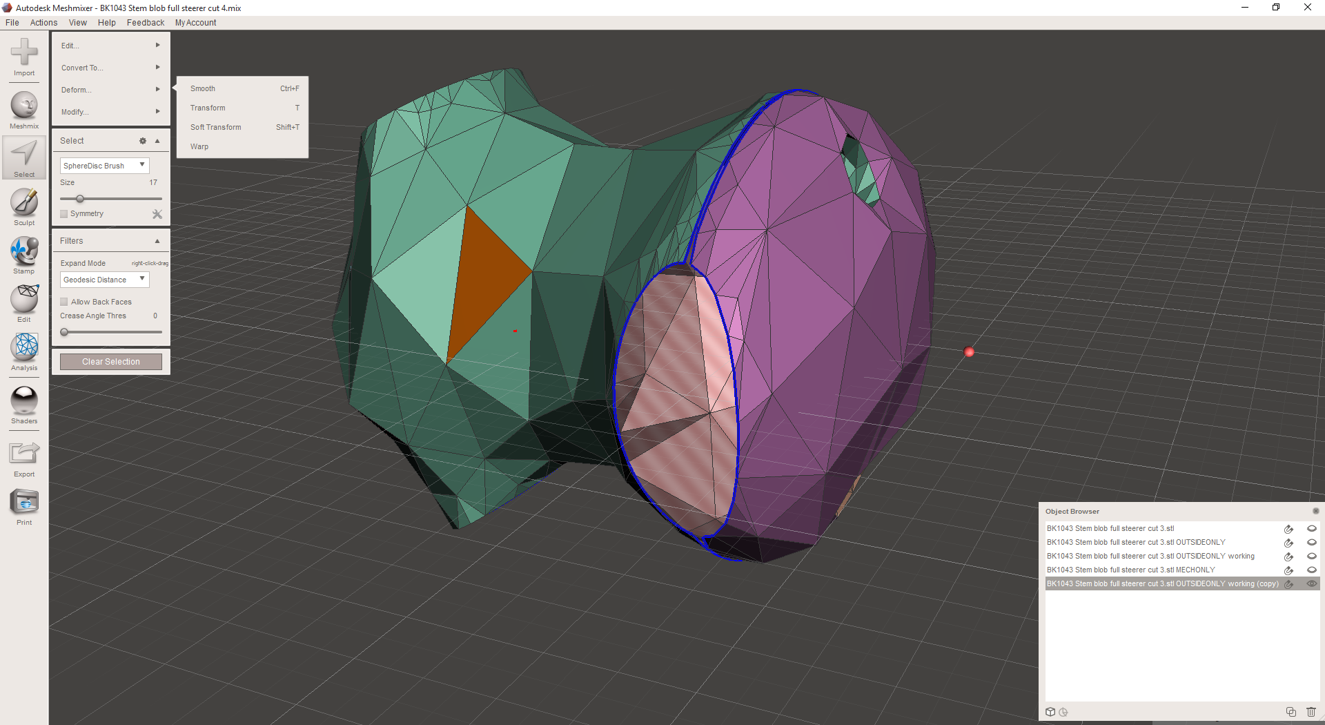
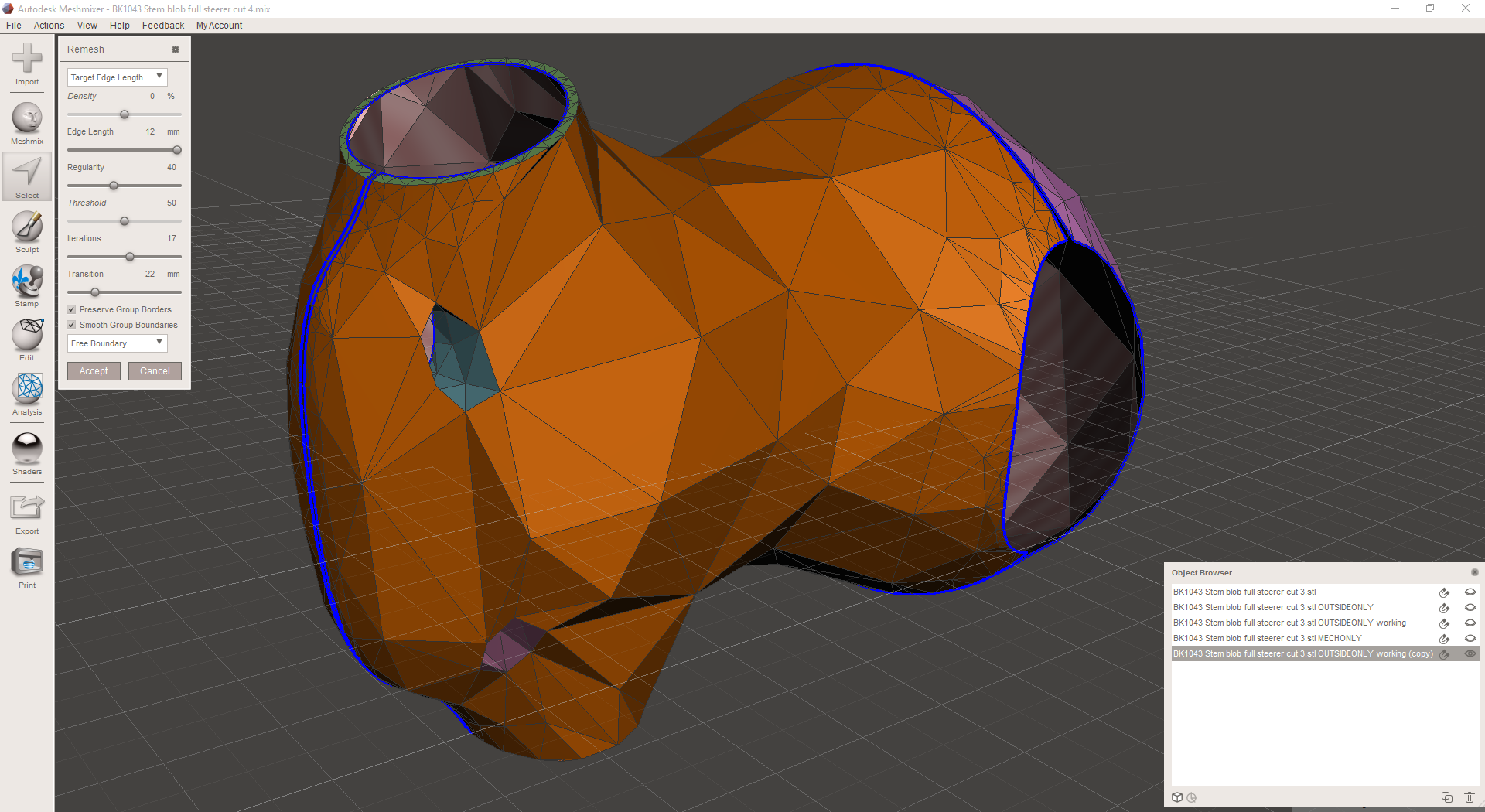
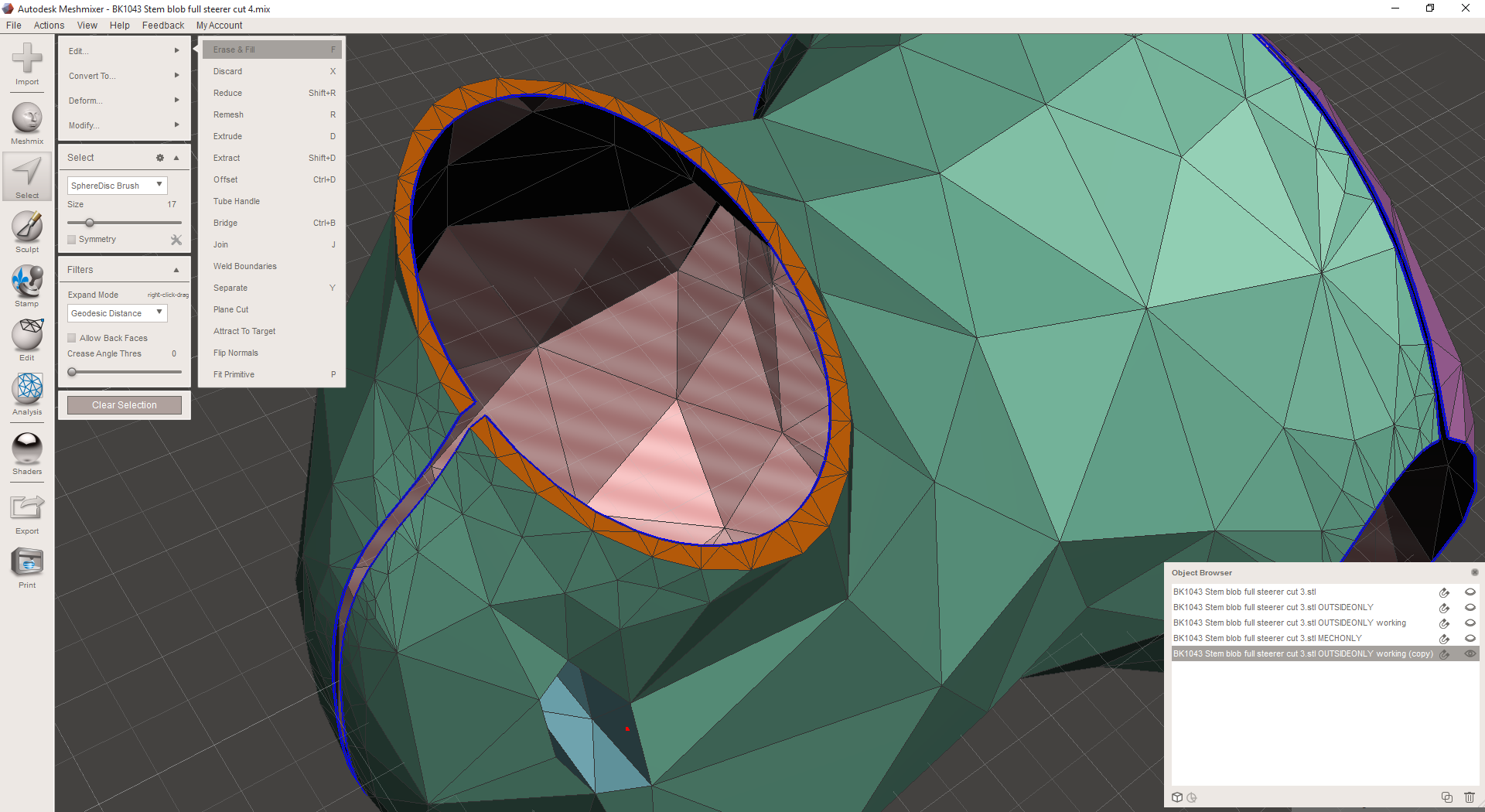
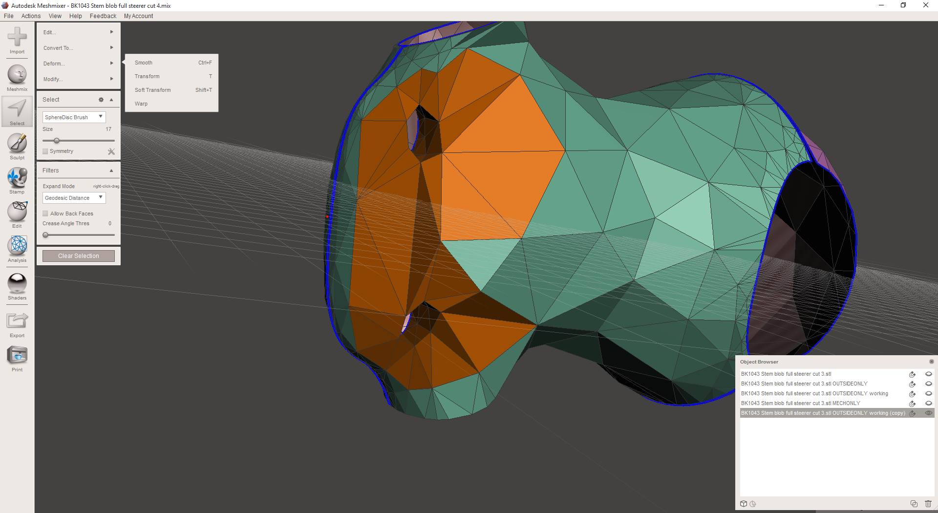
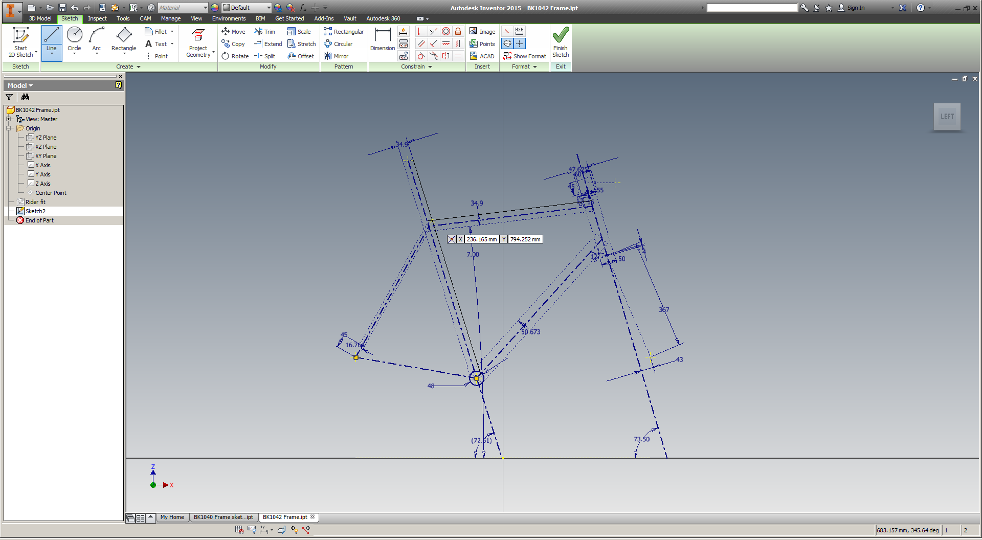
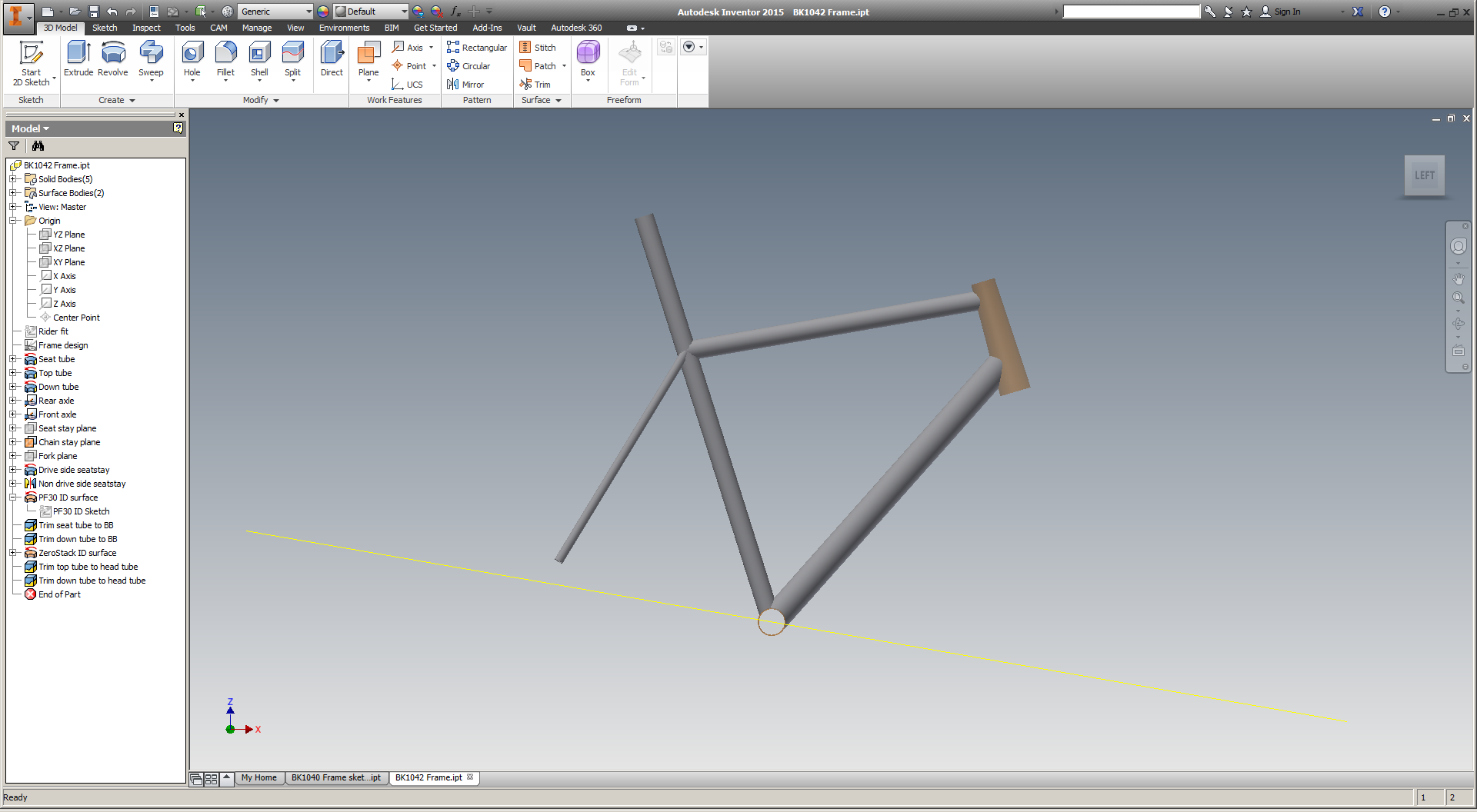
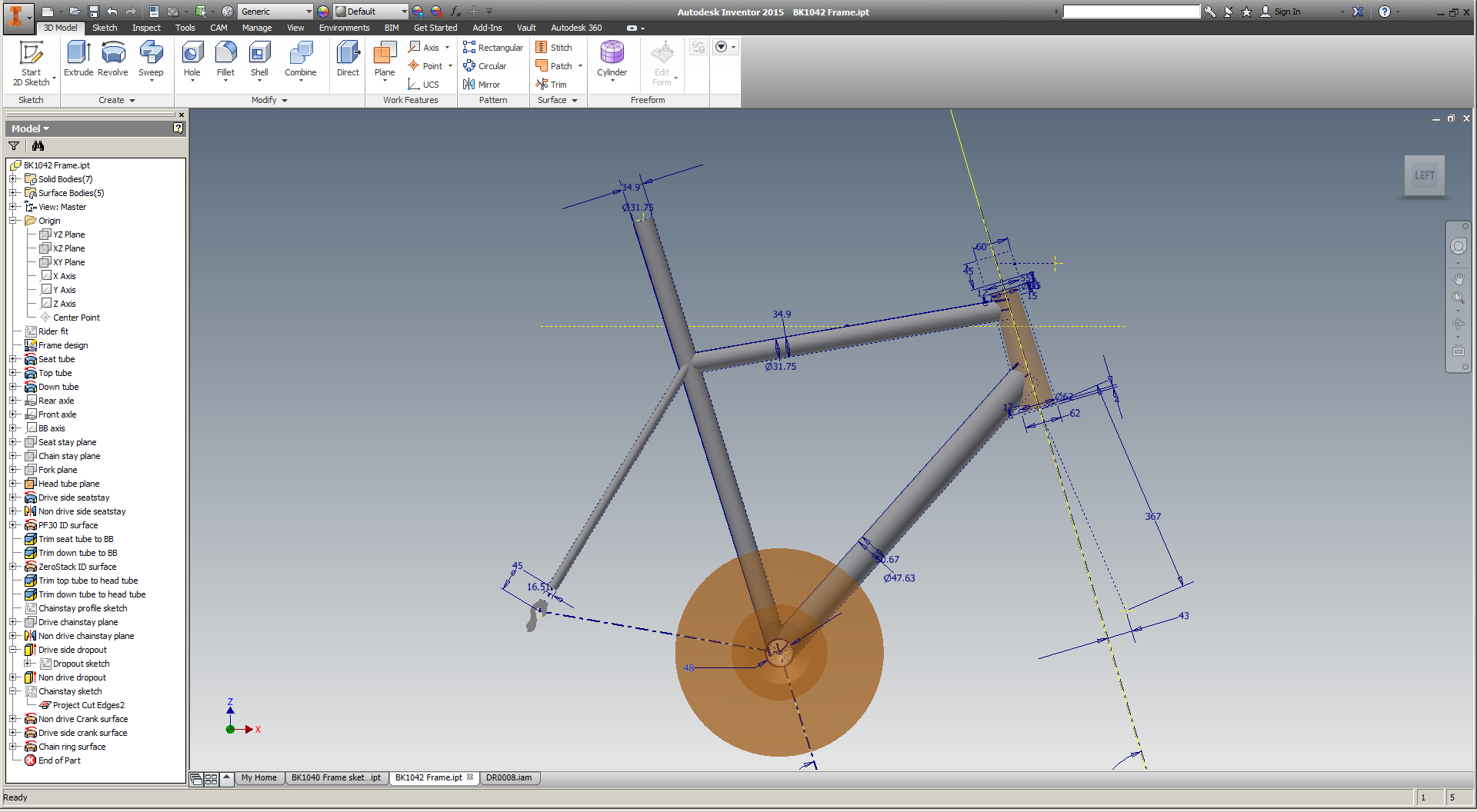
3D design tools don't act this way at all; they're totally happy letting me create designs that are utterly impossible to make in the physical world.
Now I recognize that this comparison isn't totally fair. Human eyesight is relatively well understood, whereas we know remarkably little about what *really* happens as we melt, form, and cut metal parts. But the fact remains: 3D design tools just aren't concerned with whether our designs are shit or shinola. And so when we ask them to "optimize" those designs, they give us exactly what we've asked them for.
I'd guess that this is a result (at least partly) of the traditional divide between CAD and CAM. These systems were developed by different companies and in service of different customer objectives, and in the end we've been left with a system that encodes - and then promptly decodes - our design intent in a distinctly disjointed way.
Additive manufacturing hasn't solved this source of complexity; nor, to my knowledge, has it exacerbated it. It remains with us today, and screams out to me:
Until manufacturing constraints are quantified early on in the design process, any "design optimization" that's done will be inherently inefficient - and those inefficiencies will then be repeated by separate DFM/CAM software.
This is a massive barrier in the industry today, and I know that some of the best people in both software and manufacturing are working on it as I write this. If you're one of them, or if you have experiences similar to mine, let me know - I'd love to collaborate.