Big thanks to Michael Raphael and Peter Kennedy, of Direct Dimensions, for their help with the 3D scanning - the key part of this process. Thanks also to Ryan Schmidt (of MeshMixer) and Bradley Rothenberg (of nTopology) for their ongoing support in designing 3D lattice structures.
As I hinted to a few months back, I've been scheming for a while to create an integrated design for a seatpost/saddle support to be printed in titanium. As a first step along this path, I decided that it'd be easiest to use an existing saddle shell, and design a part that would adapt the shell to fit a piece of carbon fiber tubing.
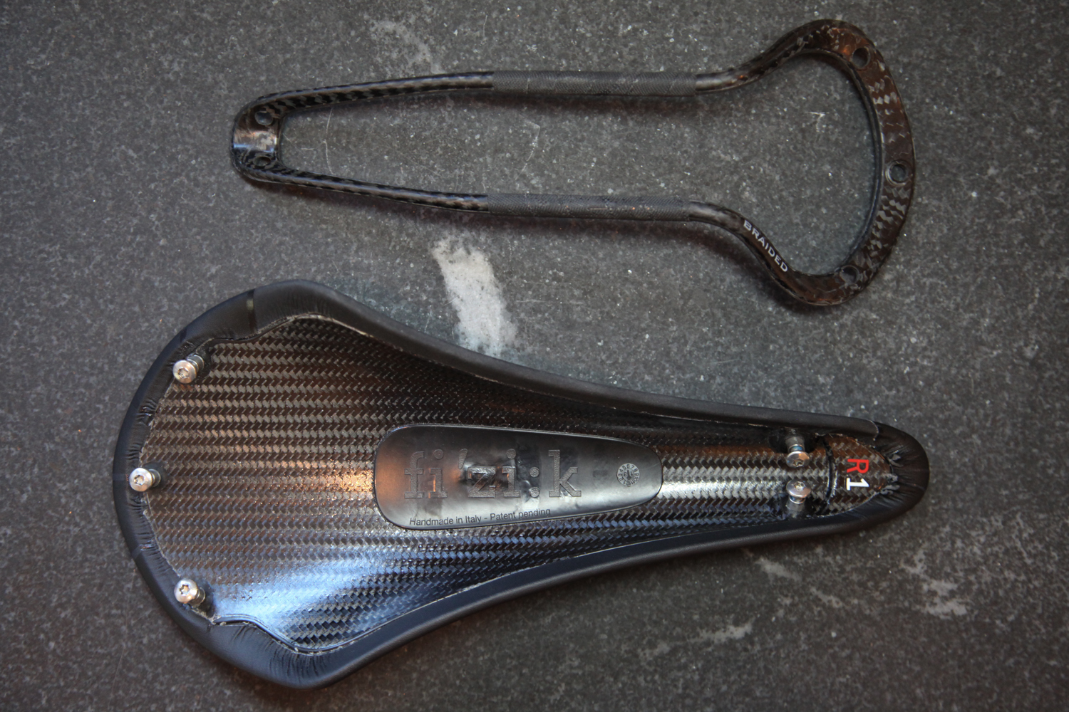
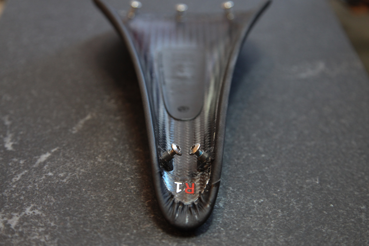
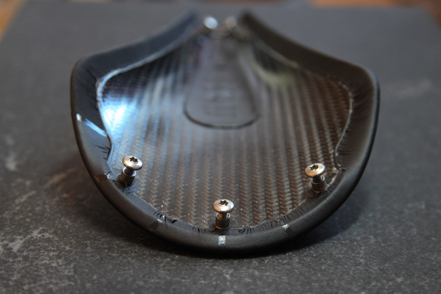
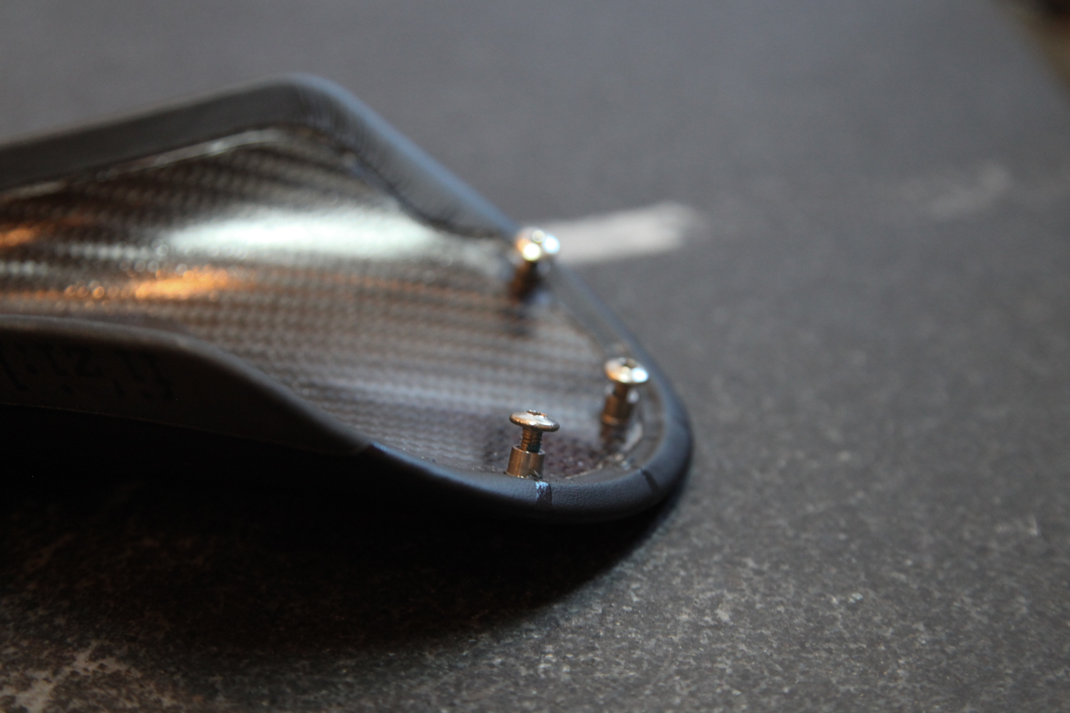
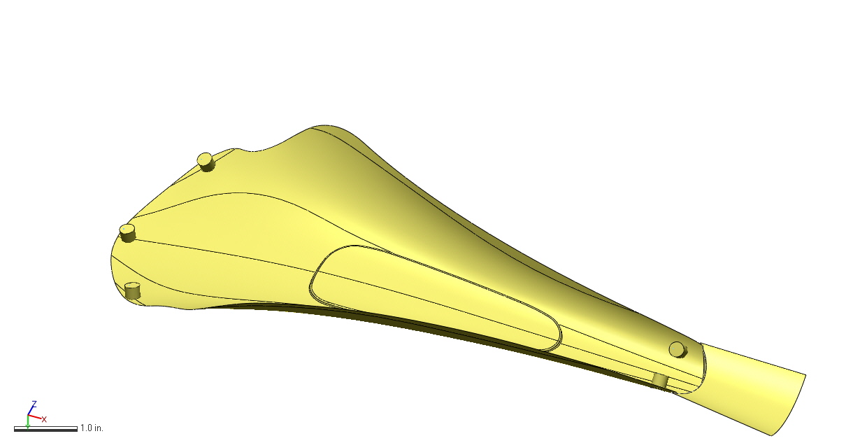
The saddle I chose consists of a carbon fiber shell, some minimal padding, and five female threaded bosses: three in back, two in the front. The bosses fit through the shell, so that they protrude through the underside; they will be my part's connection points. As you can see below, the saddle comes with (and isn't meant to be separated from; this is a decidedly off-label use of this part) a loop shaped rail part; I'll be discarding that and building my own 3D printed titanium part instead.
The first step in my design process is pure reverse engineering. I need to understand where each of those bosses is in 3D space, so that I can design a part that fastens to them securely. In order to do this, I worked with Direct Dimensions to scan - and then reconstruct - the part to a point where I could design around it.
Reverse engineering via 3D scanning is a process of interpolating, smoothing, and in the end often guessing the design intent behind an observed feature. The same is the case with basically any form of reverse engineering, of course; if you measure (via calipers, for instance) a feature to be 100.005mm, you'll generally assume that it was intended to be 100mm. With simple rectilinear parts this process is relatively straightforward, but with more complicated ones - especially ones that include a combination of complex curvature and manual fabrication methods - it can look a lot like art.
Regardless, the first step is to acquire some data on where exactly the part in question *is.* Direct Dimensions started by laser scanning my part with a Faro Edge arm and an HD probe:
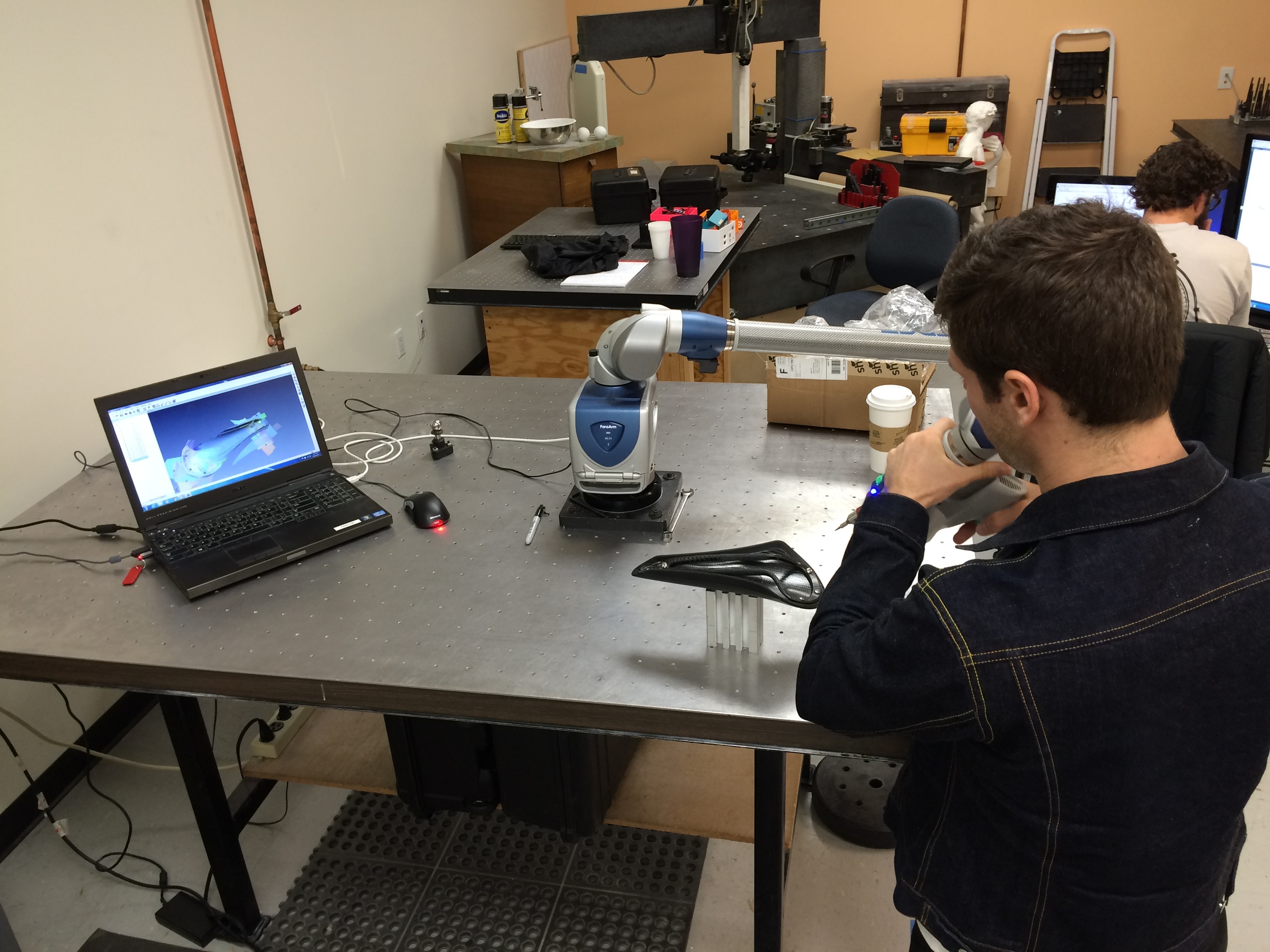
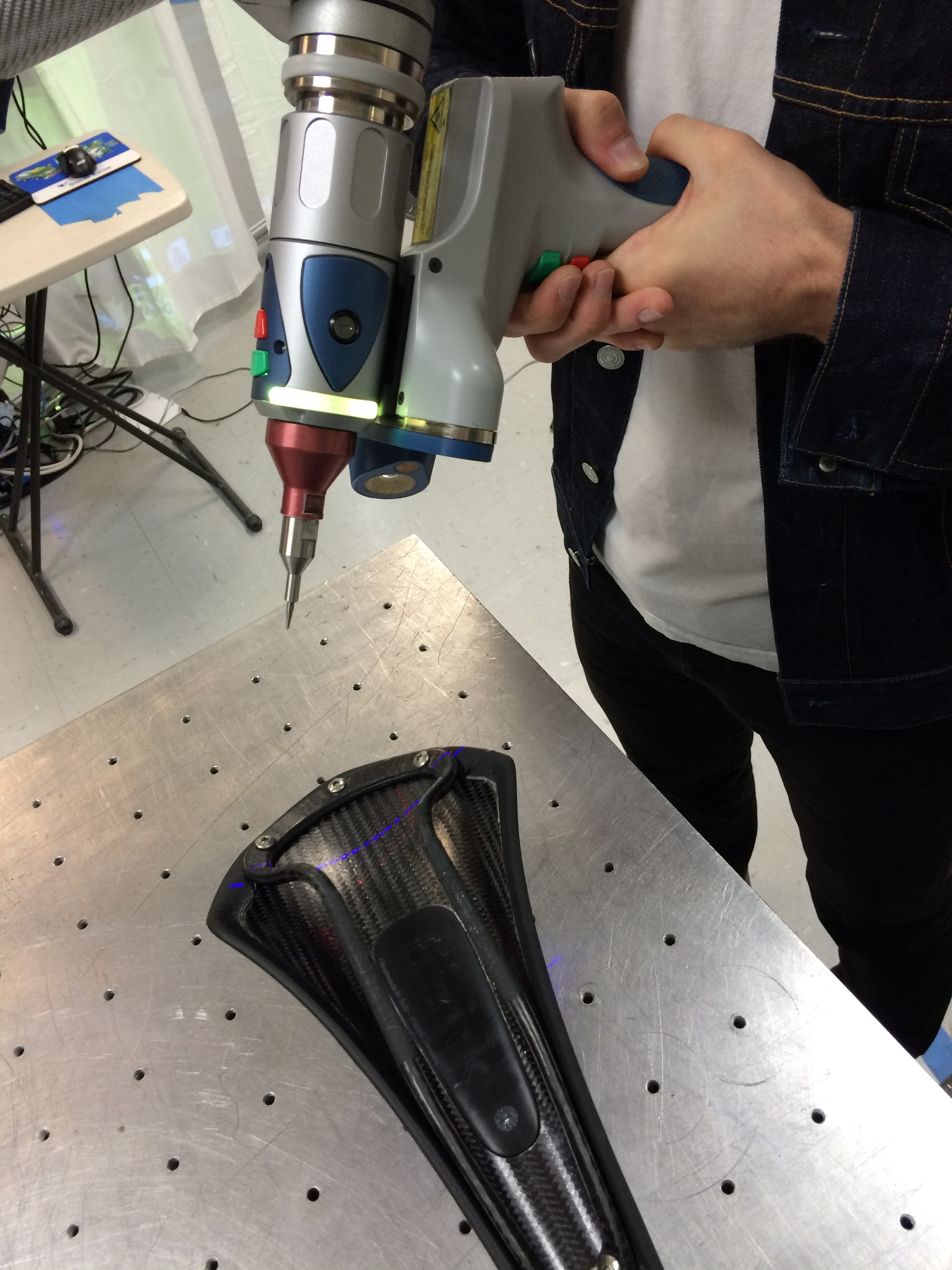
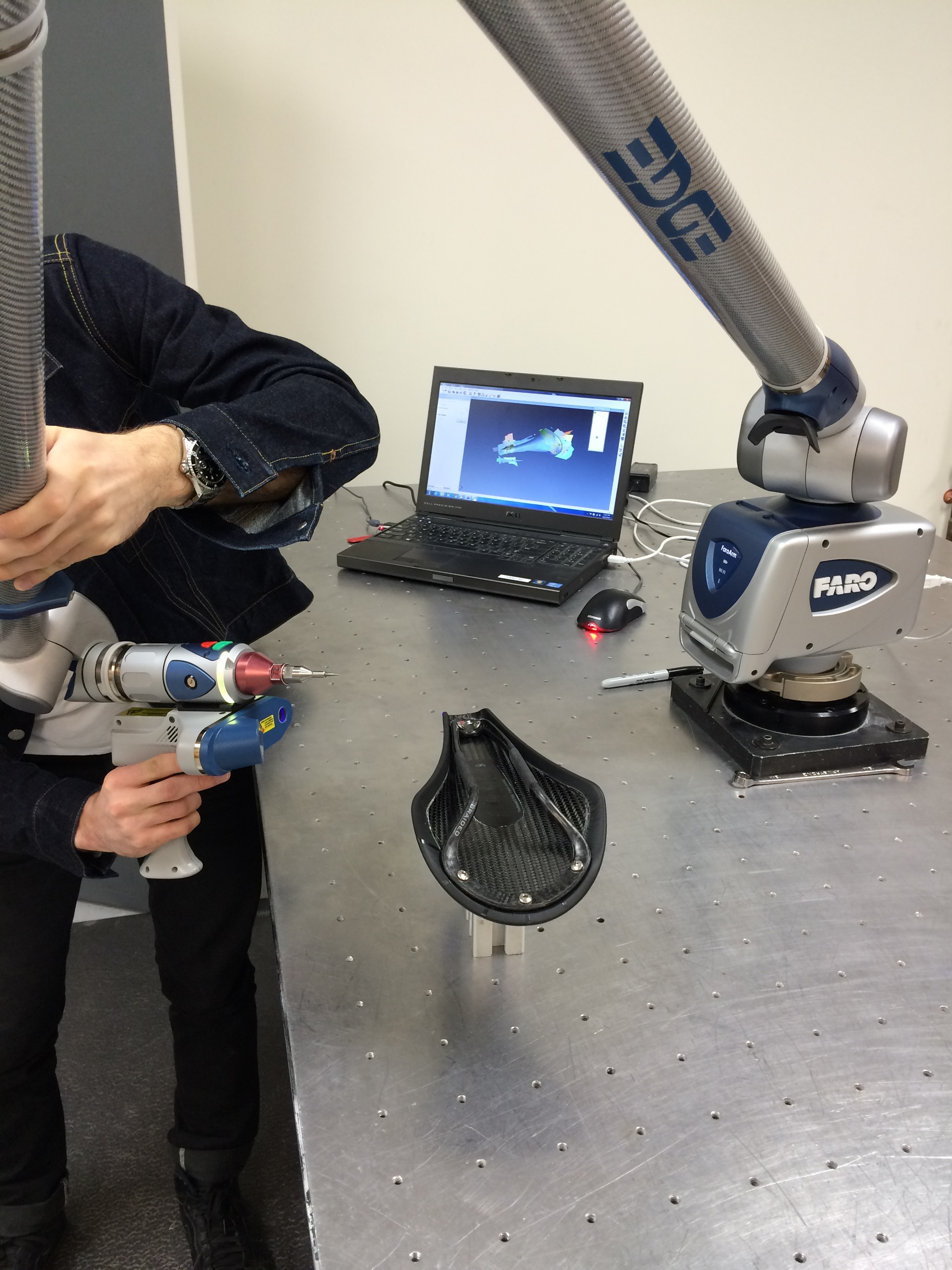
This is an interesting hybrid system: the arm itself knows where it is, and the non-contact laser scanning probe knows how far away (and in what direction) the thing it's pointing at is. When combined, the single-point repeatability of the system is below .1mm.
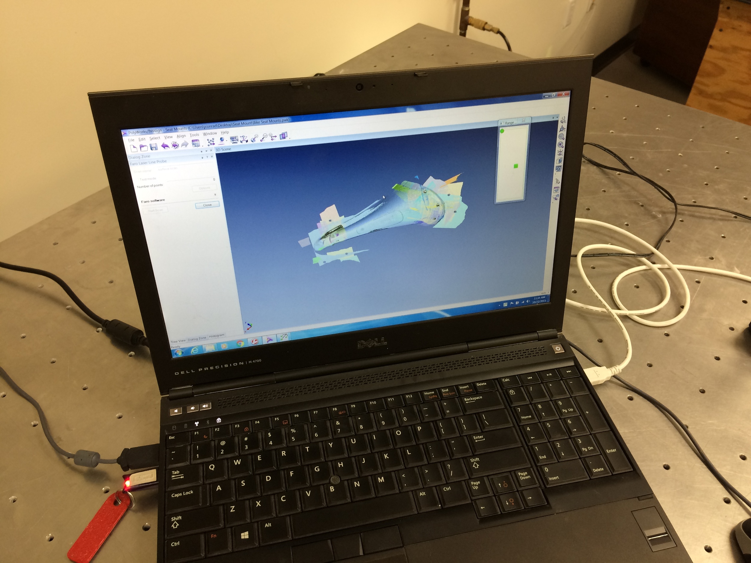
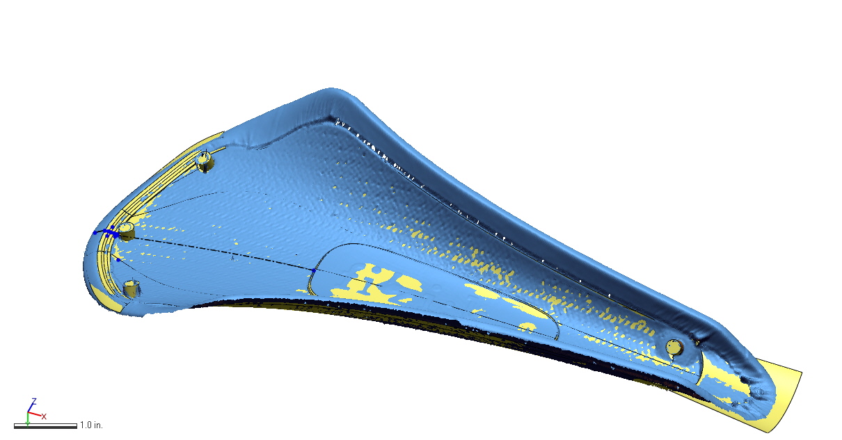
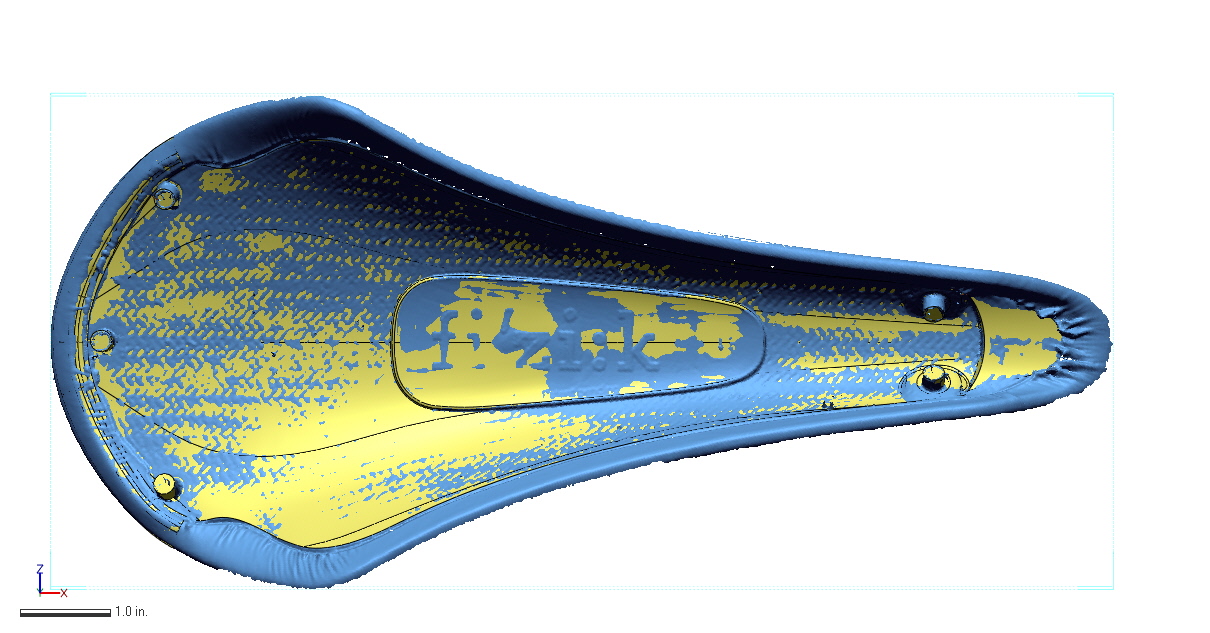
From the point cloud generated by the probing system, Direct Dimensions was able to create a raw polygon mesh:
This mesh is a representation of the underside of the saddle shell; you can see the five bosses as well. It's a start, but not particularly useful for designing a mechanical assembly. To get there, Direct Dimensions used two methods:
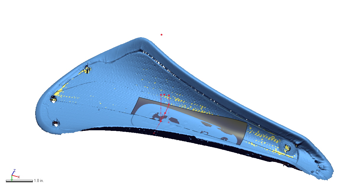
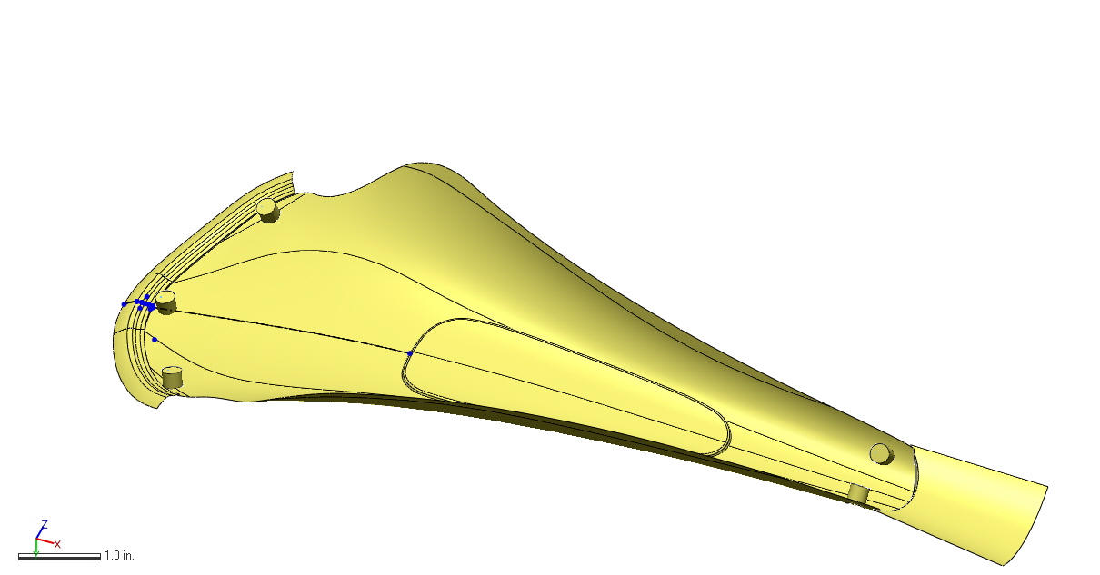
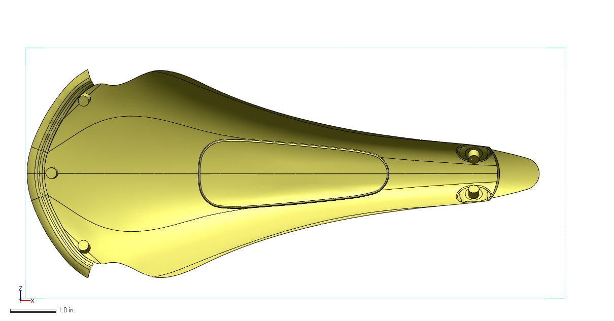
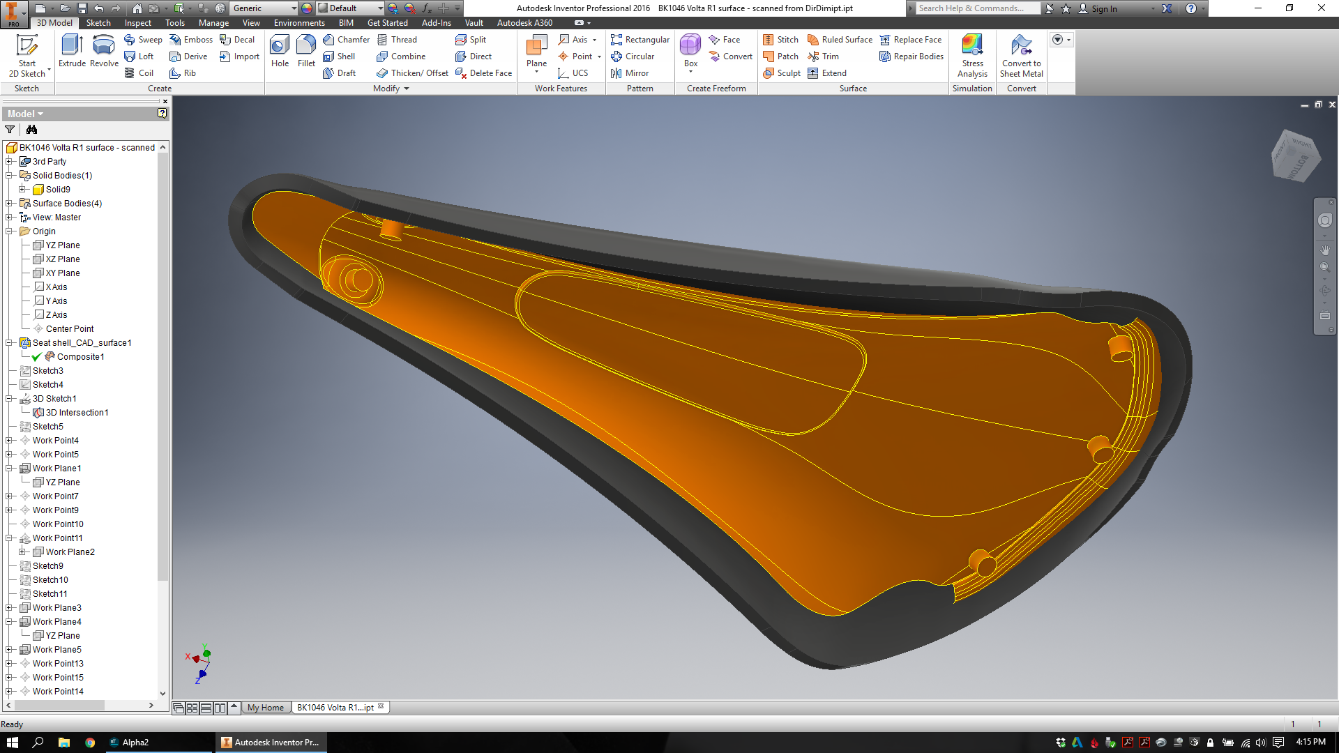
First, they used a method called "rapid NURBS" to wrap a NURBS surface to fit the complex shape of the saddle. This is a fairly quick method (an hour or two of work) and results in something that fits all the weird contours and fine features pretty accurately. As you can see here, there's pretty high feature resolution in the model, which can be useful if I need to make sure to avoid (or fit closely to) something. On the other hand, though, the surface is difficult to manipulate and a little hard (due to its complexity) for me to even open up and play with in Inventor.
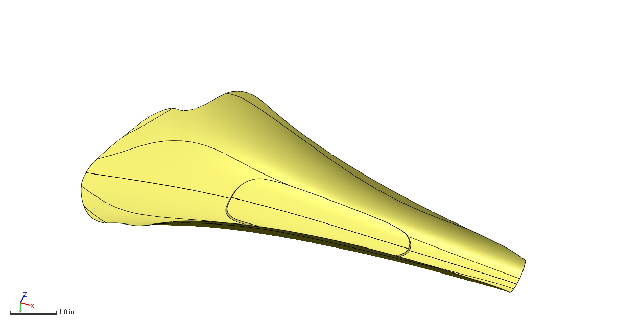
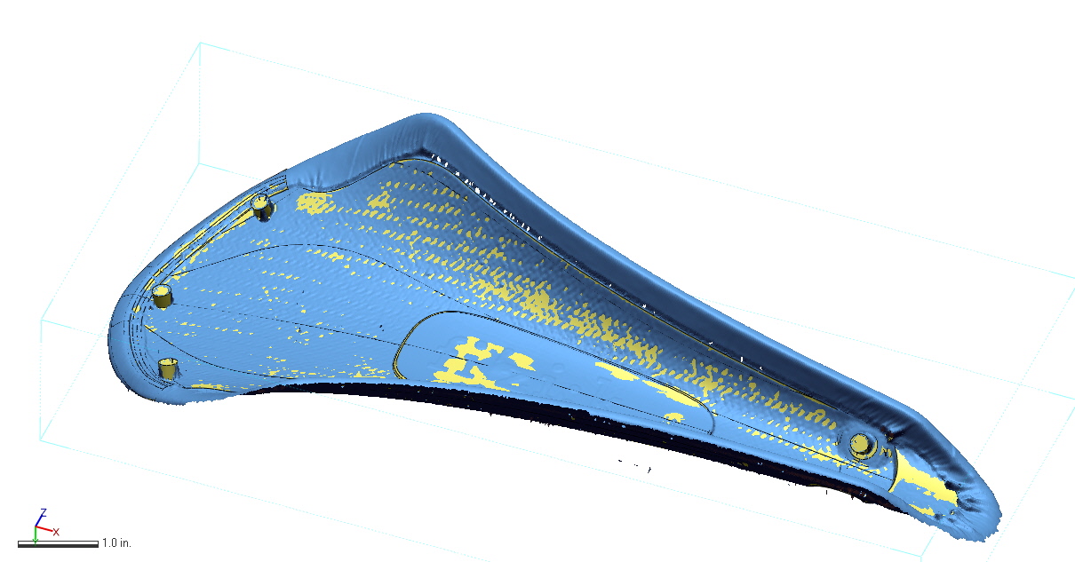
For a more useable (but less detailed) model, Direct Dimensions made a CAD surface for me as well. This is a much longer and more manual process, taking most of an afternoon. Here, individual surfaces are modeled and stitched together to create a shell that represents all of the necessary feature geometry accurately, but with a bit less precision than the rapid NURBS model. You can see roughly how the model was created below:
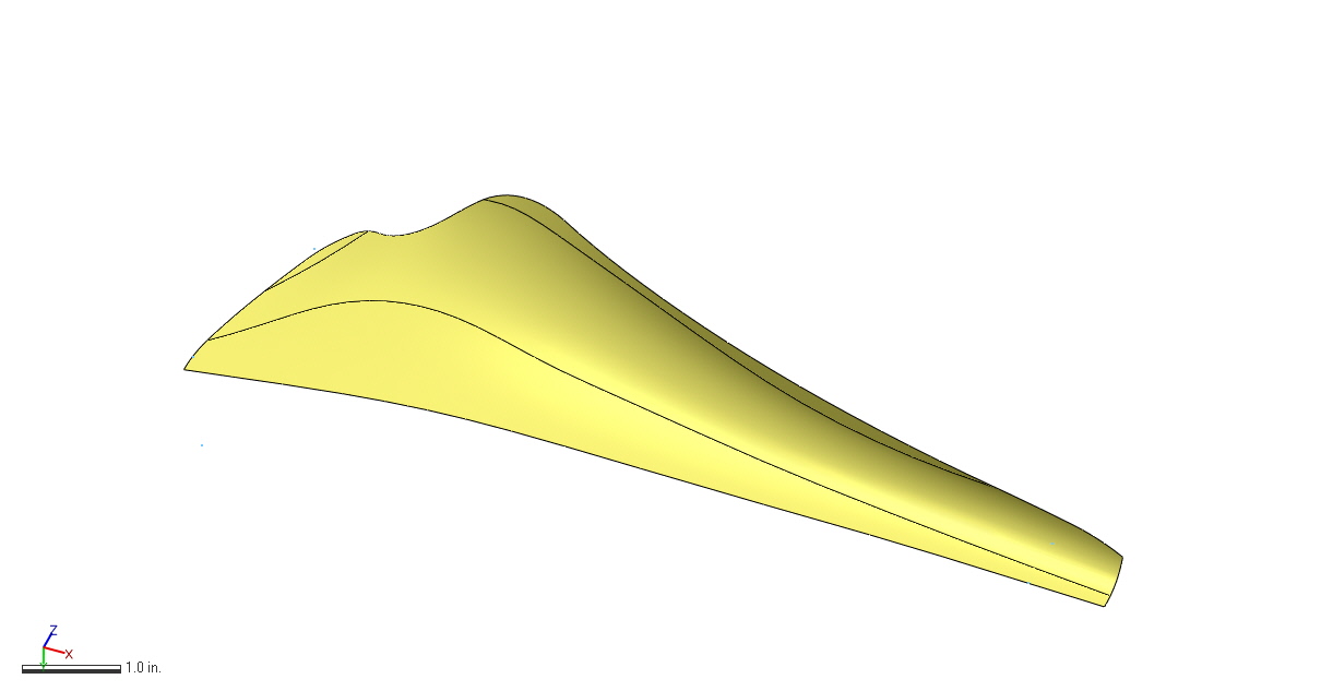
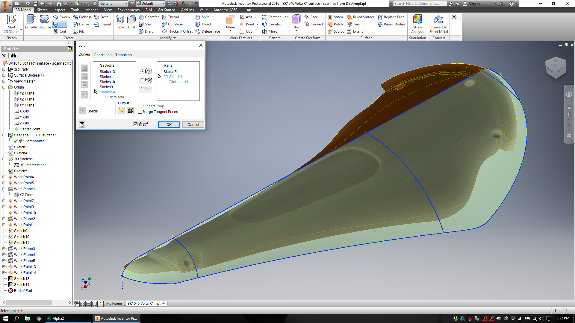
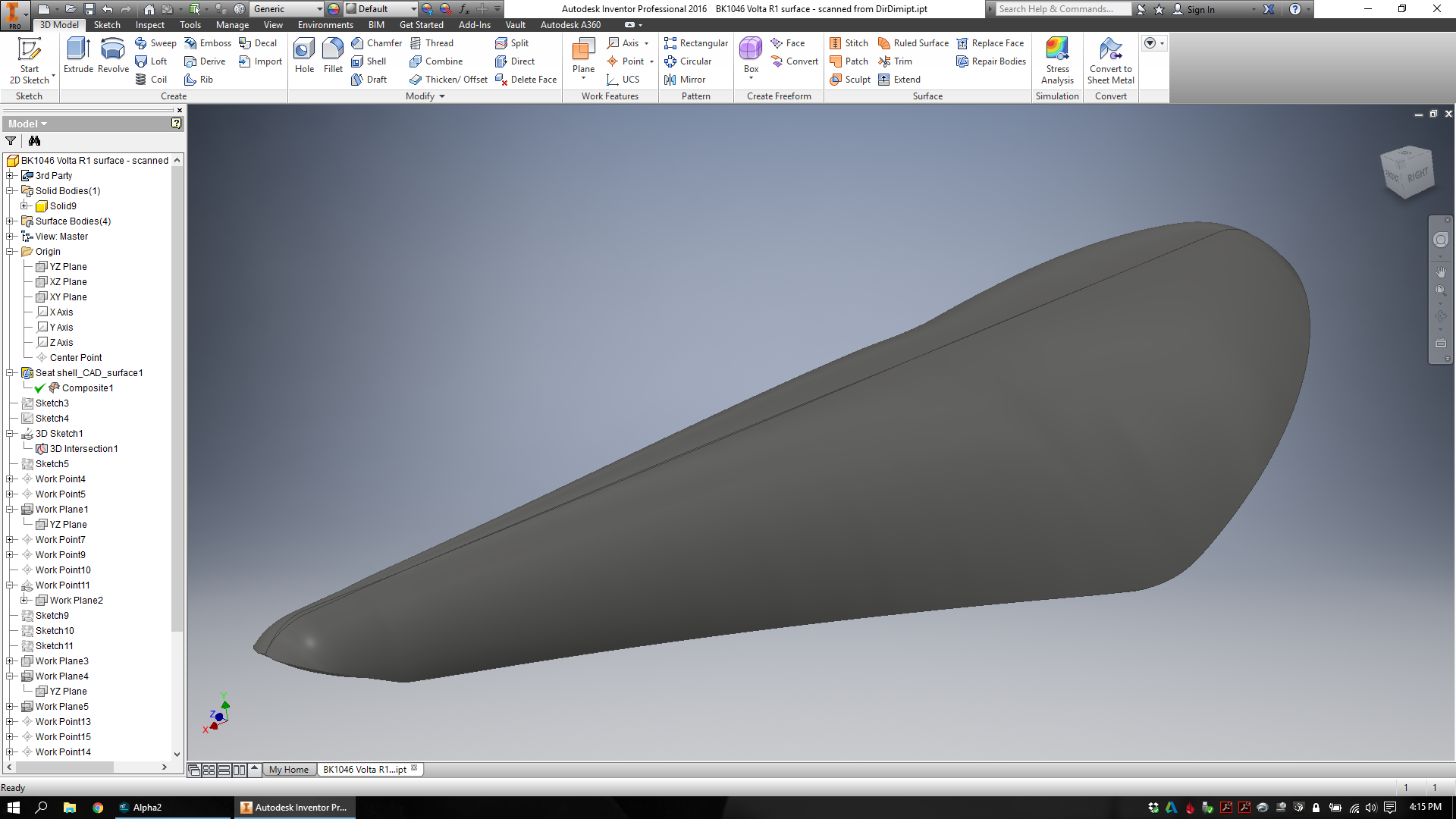
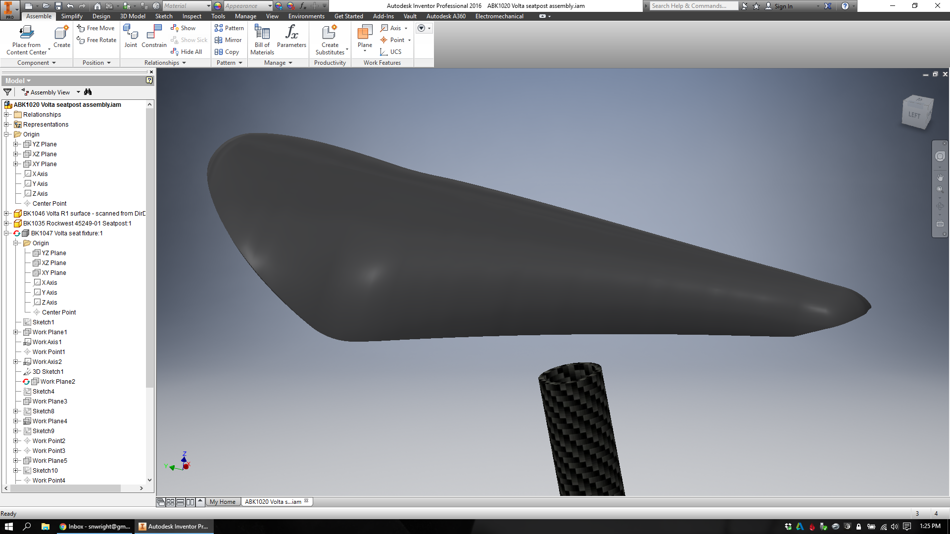
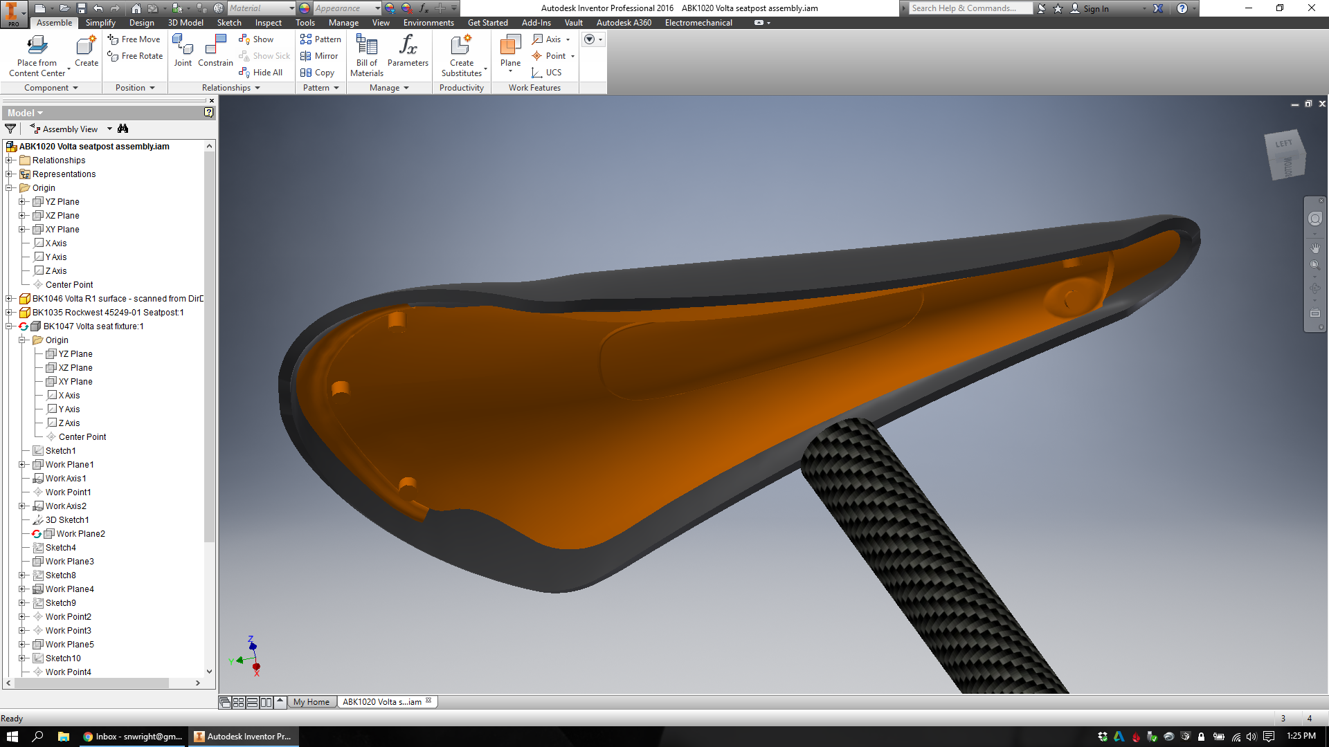
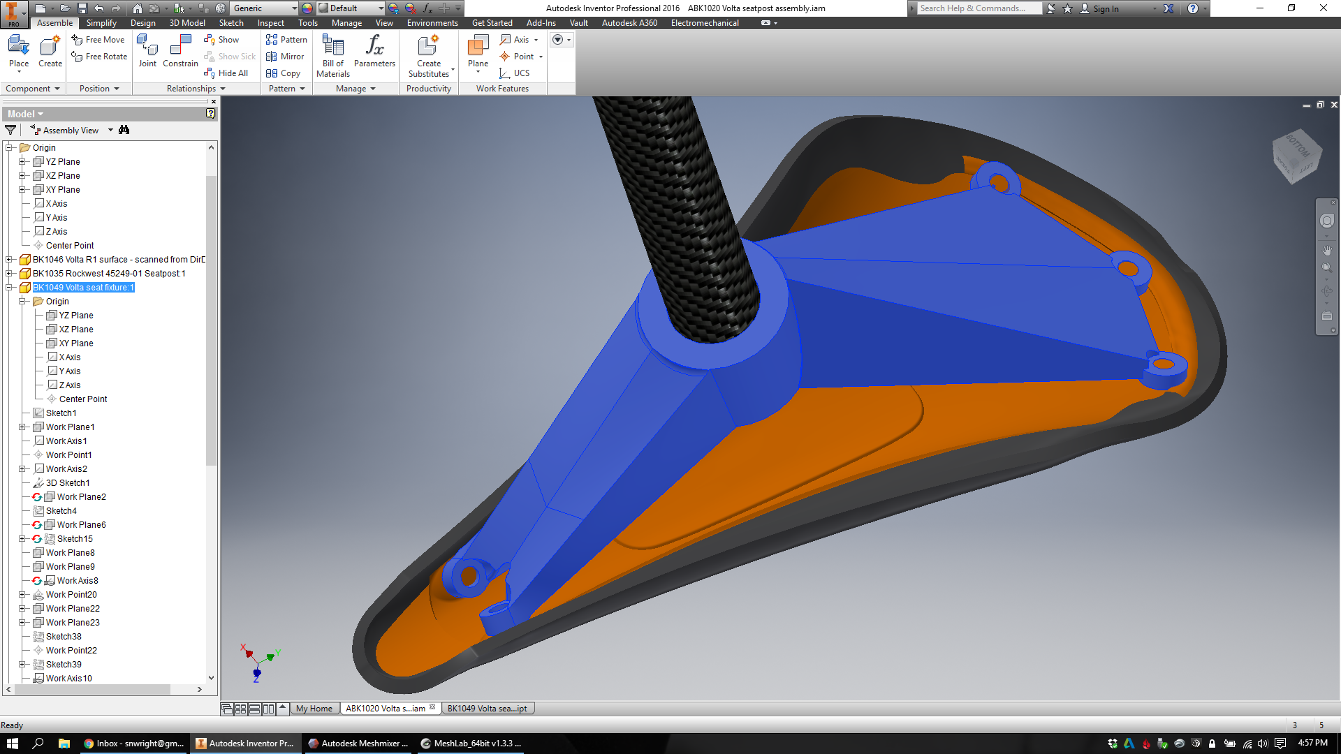
At this point, I finally had a model that I could begin to design around. I started by creating a quick lofted part that would stand in (just visually) for the saddle's exterior surfaces:
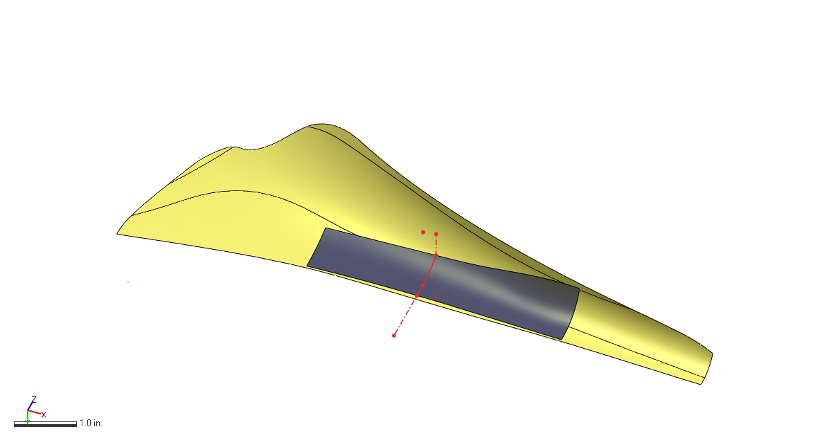
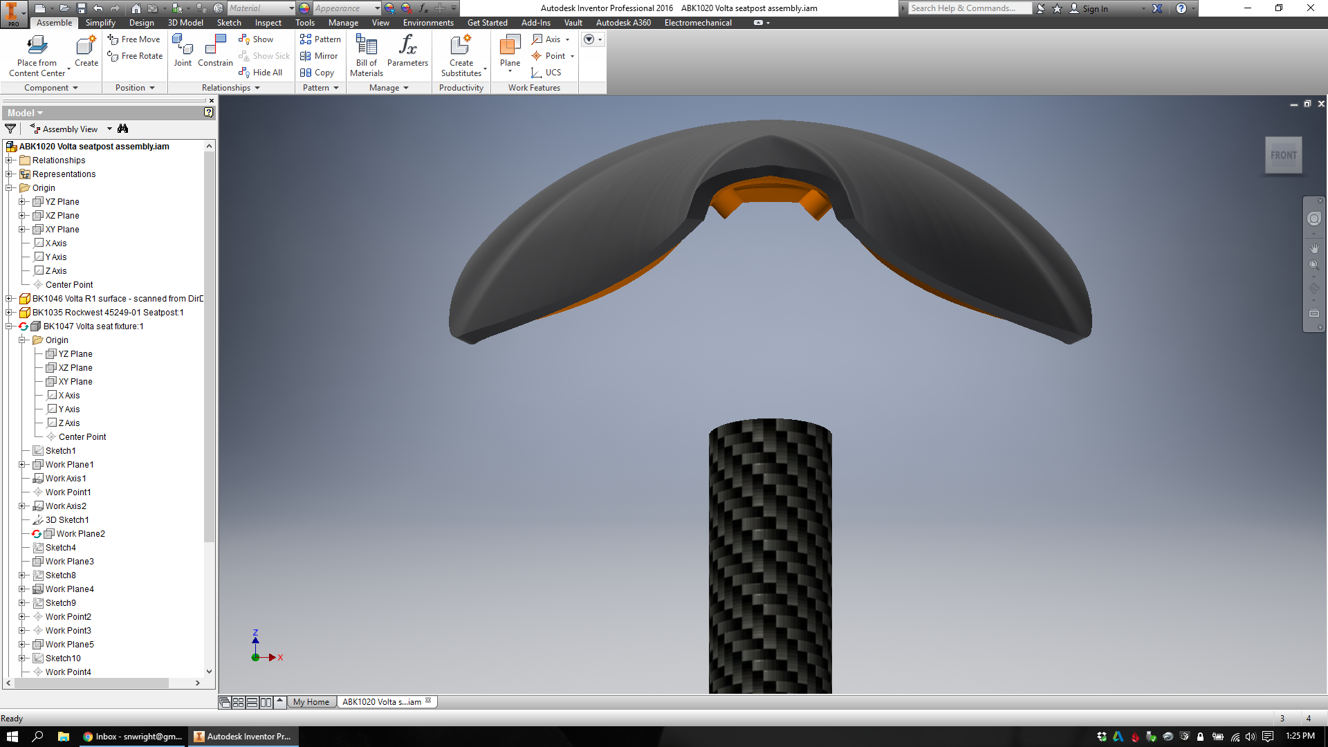
Then I placed the saddle (my lofted exterior + Direct Dimension's underside) into an assembly in Inventor, and added a carbon fiber seatpost to connect to.
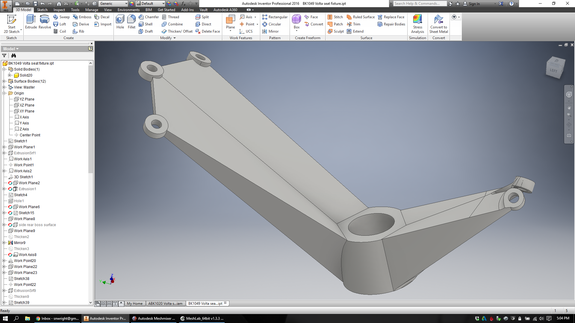
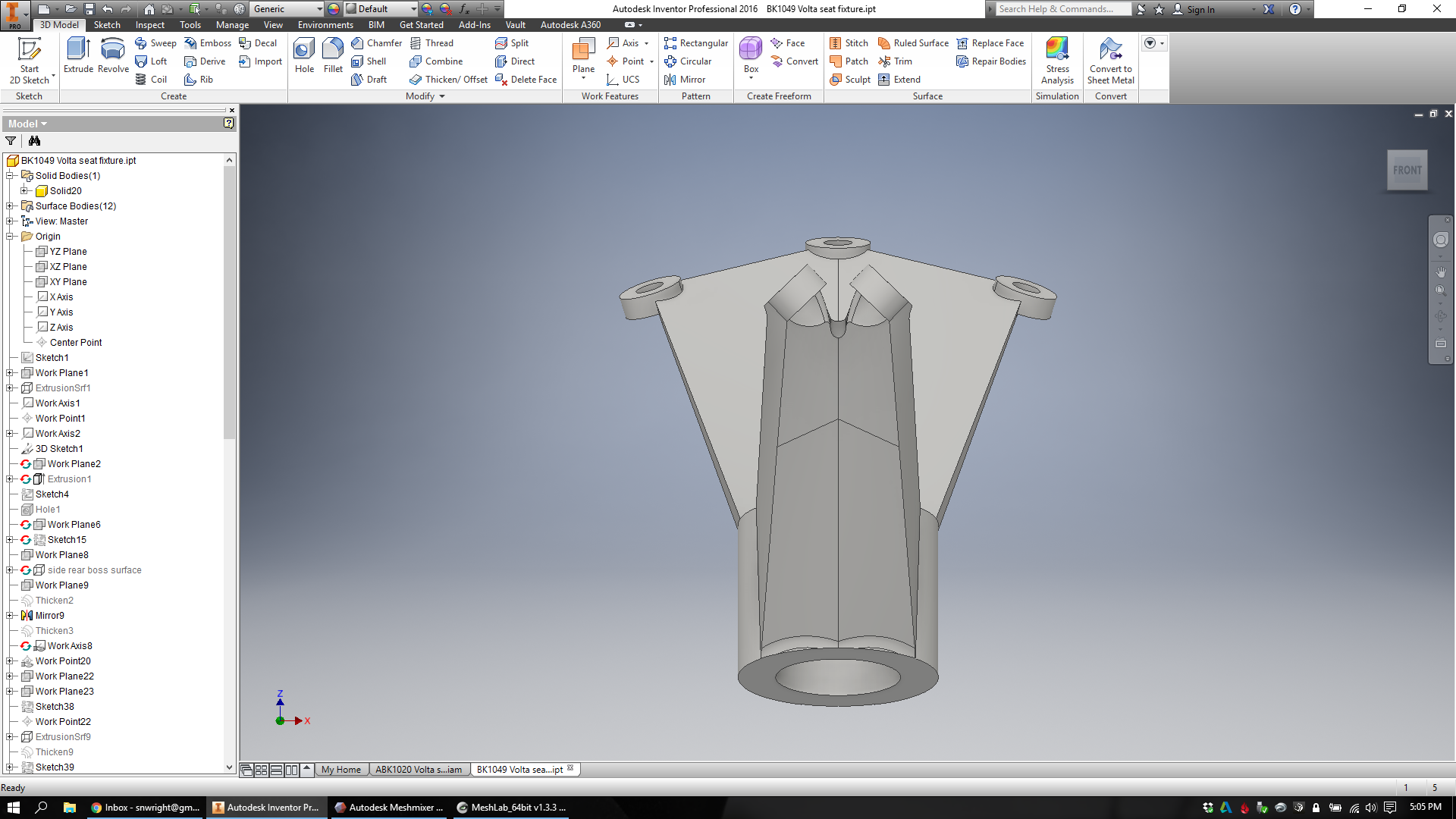
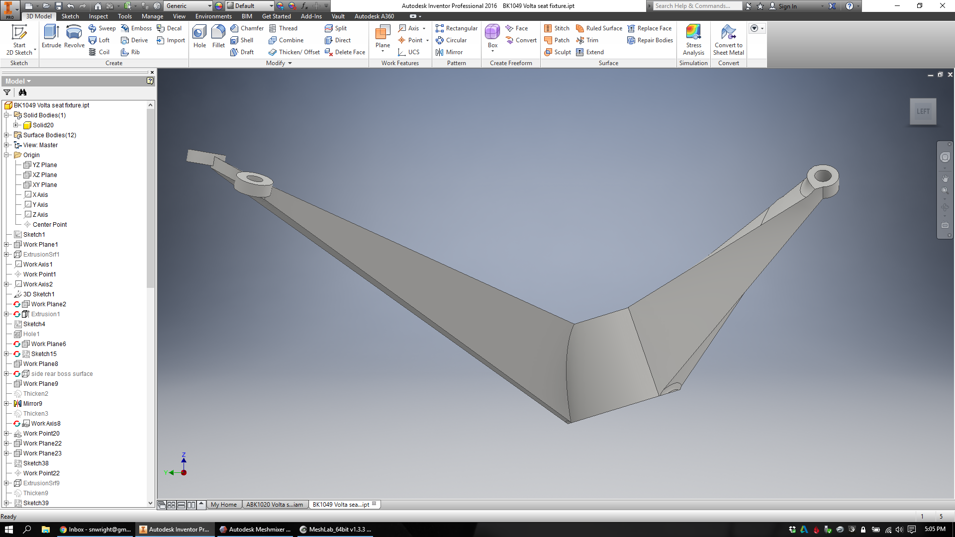
At this point I'm finally ready to start designing. I begin by creating a new part in Inventor that represents the design space available for my lattice:

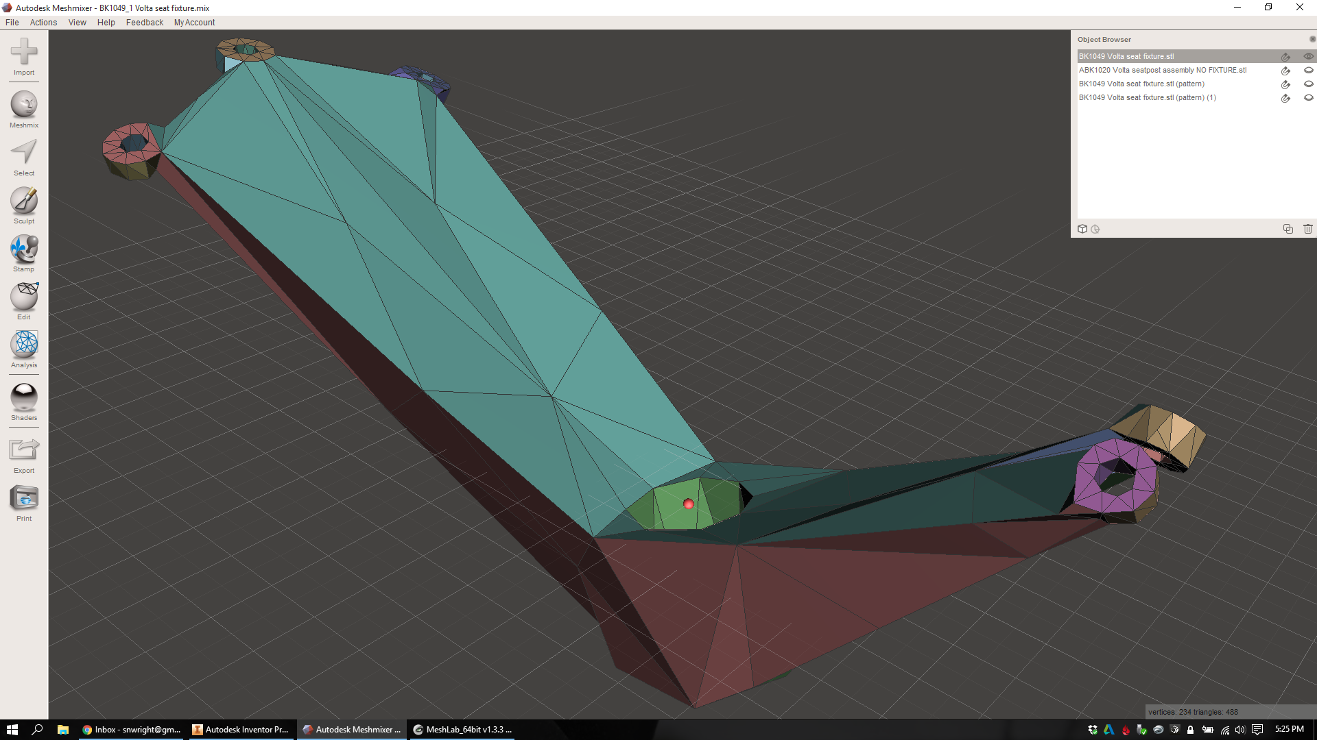
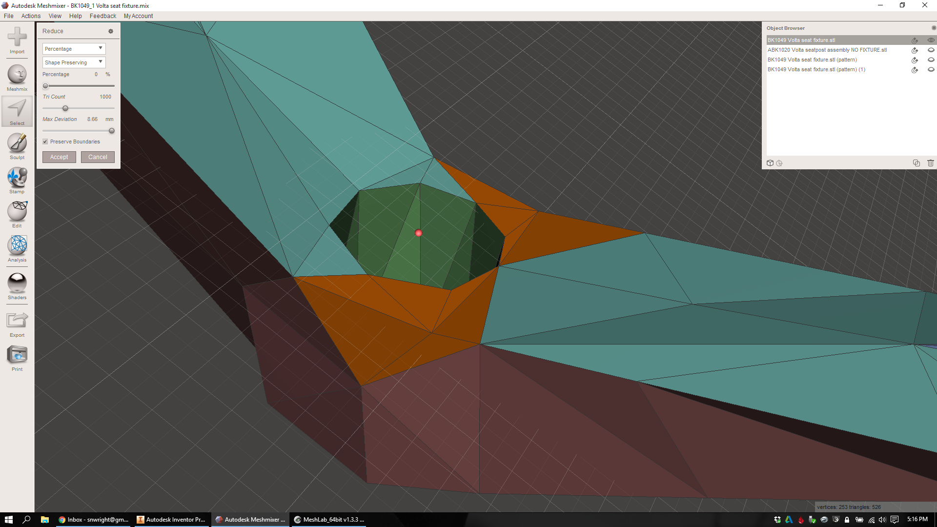
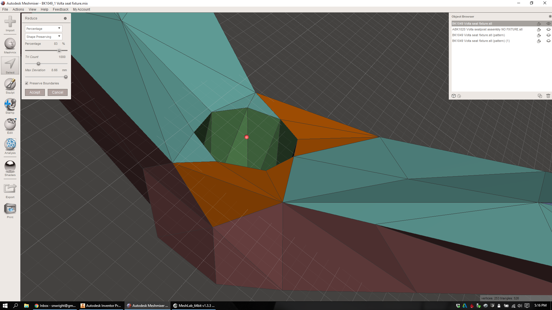
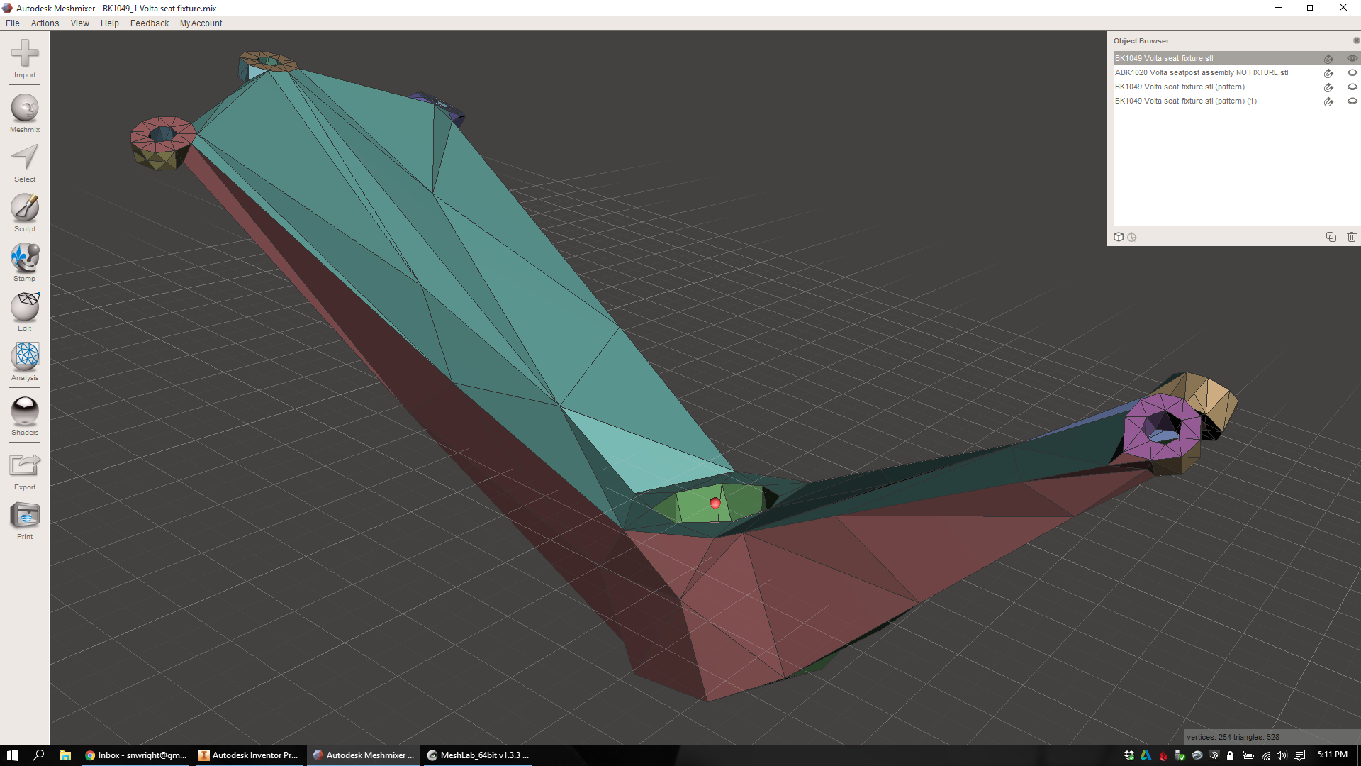
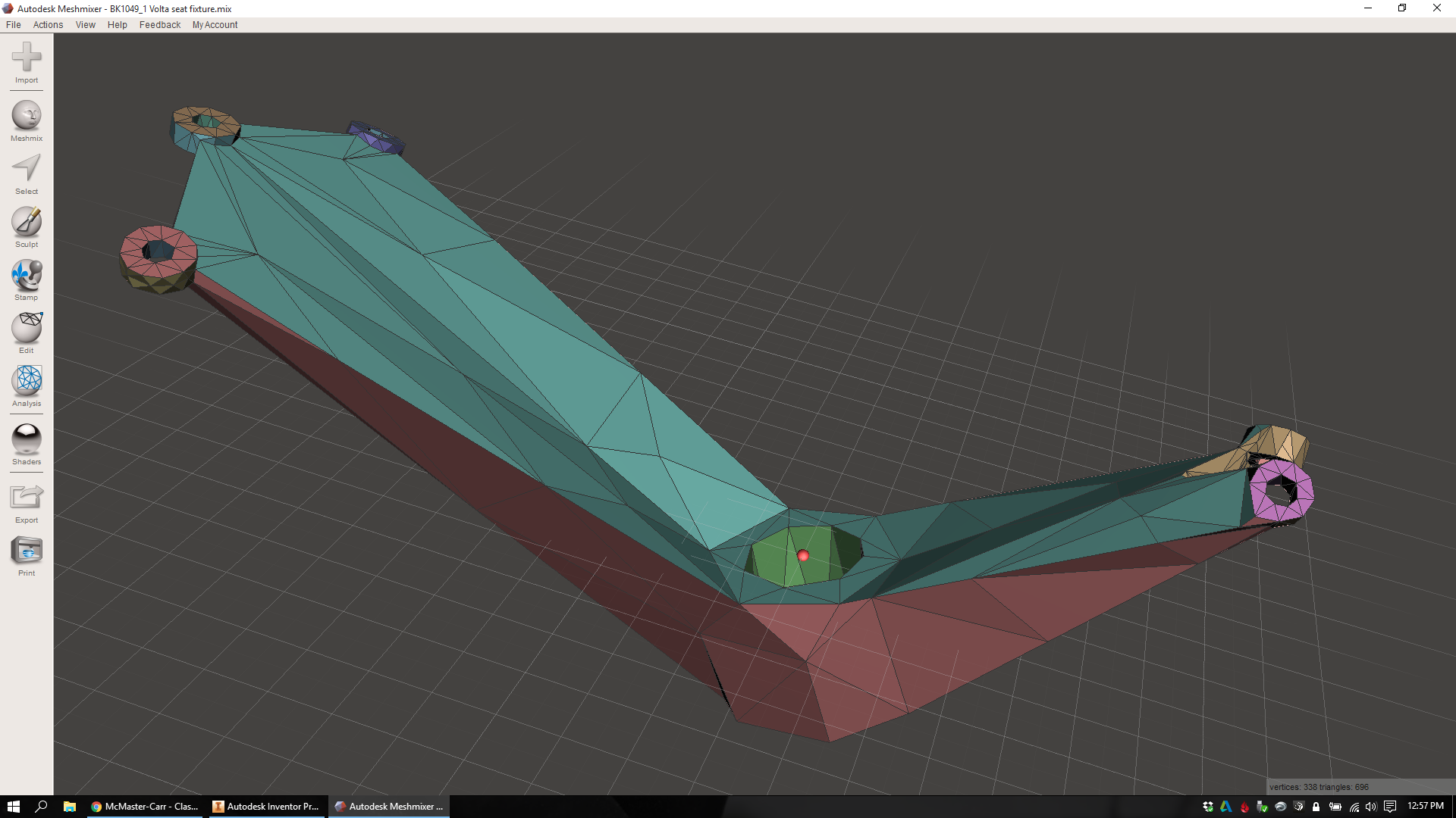
Then I bring an STL of the design into MeshMixer and make the mesh way, way less precise. This process involves selectively remeshing (and reducing the mesh quality of) face groups one at a time. Eventually I'll record a time lapse video of the whole thing, but for now you can see a little of the process below:
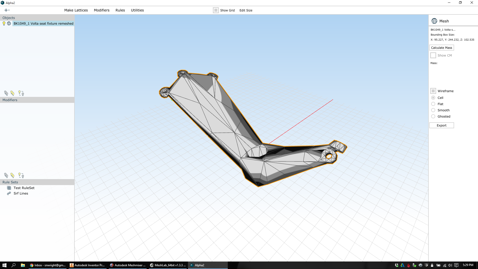
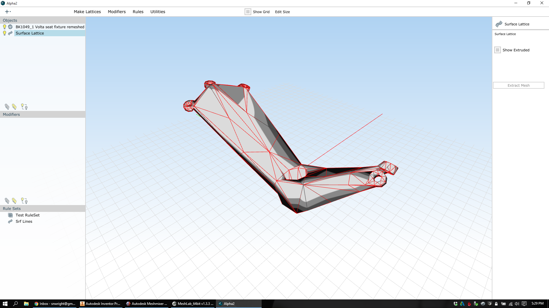
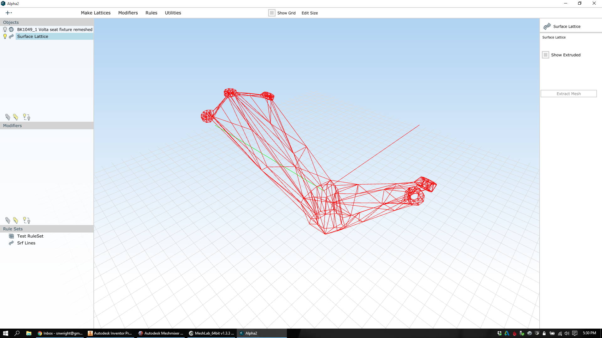
From this low resolution mesh I'm finally able to create my lattice. I export an OBJ file, bring it into nTopology Element, and create a surface lattice with beams at each one of every triangle's edges.
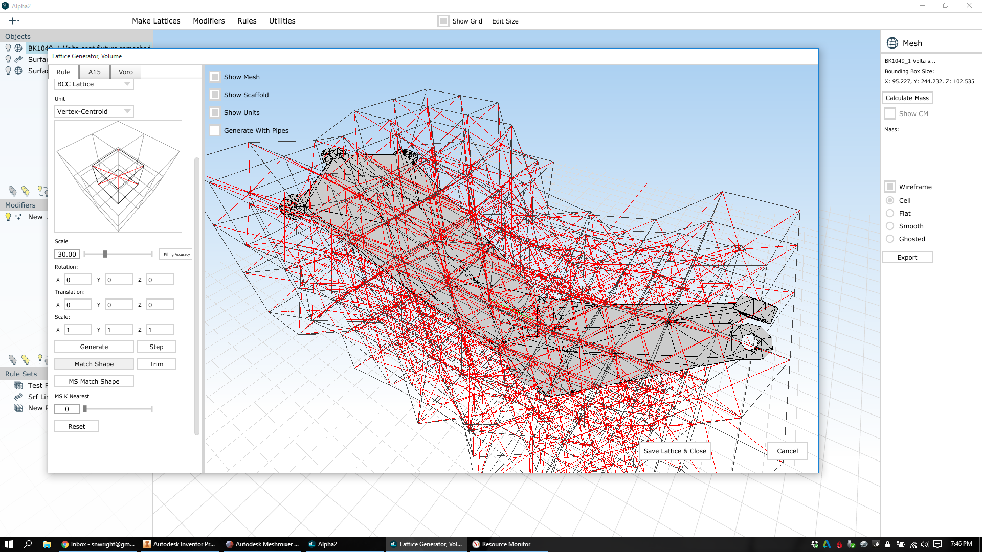
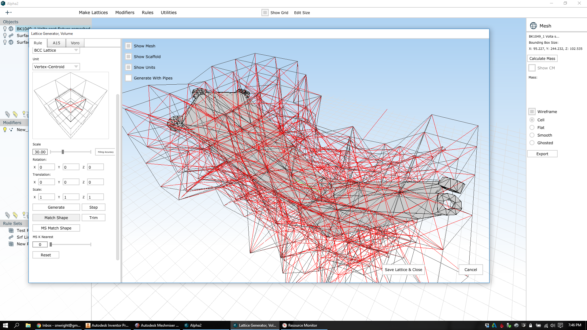
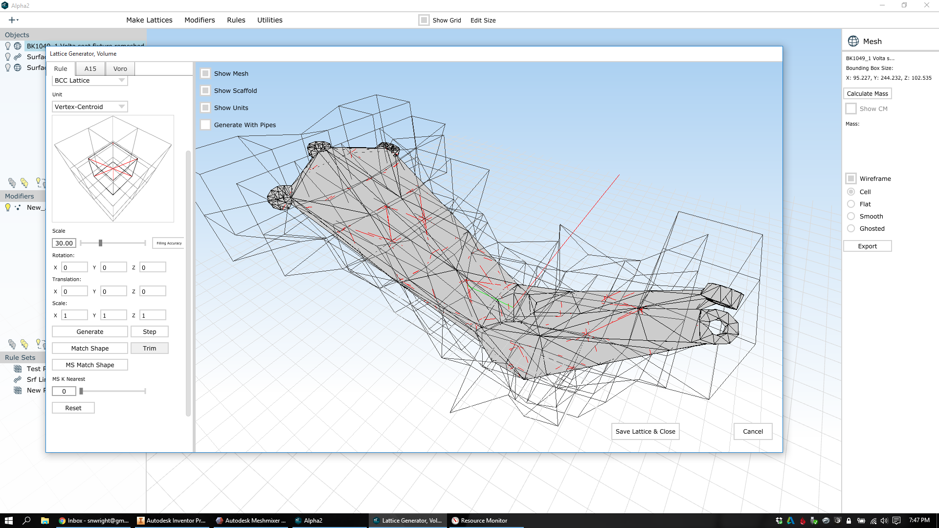
Next, I create a volume lattice on the inside of the part. I've chosen a large cell size and a vertex-centroid cubic cell structure. When I generate the lattice, nTopology Element only creates the lattice cells whose centers fit within the part. In order to make sure the whole volume is at least partly filled, I step the volume lattice out a few levels, and then warp it to conform to the volume. Then I trim the outlying cells, leaving only the beams that lie fully within the design space.


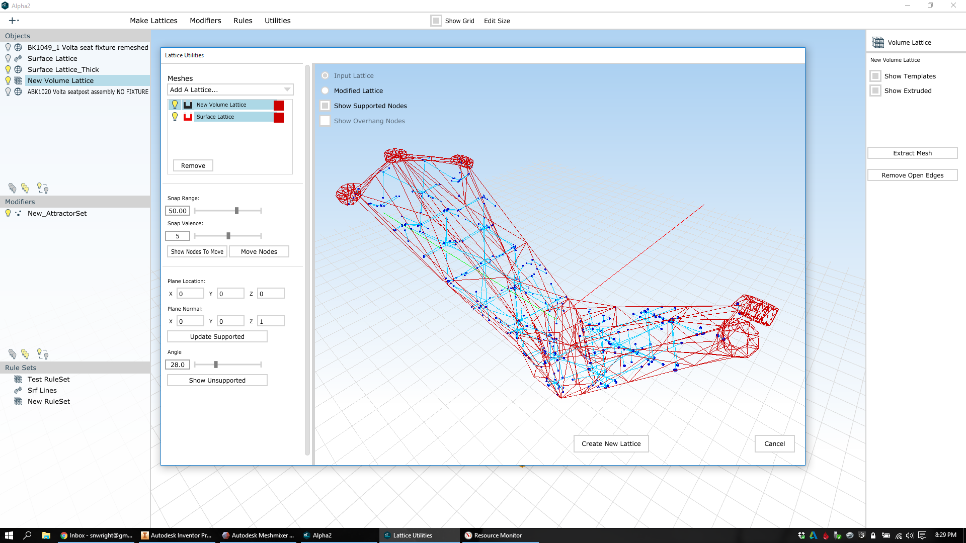
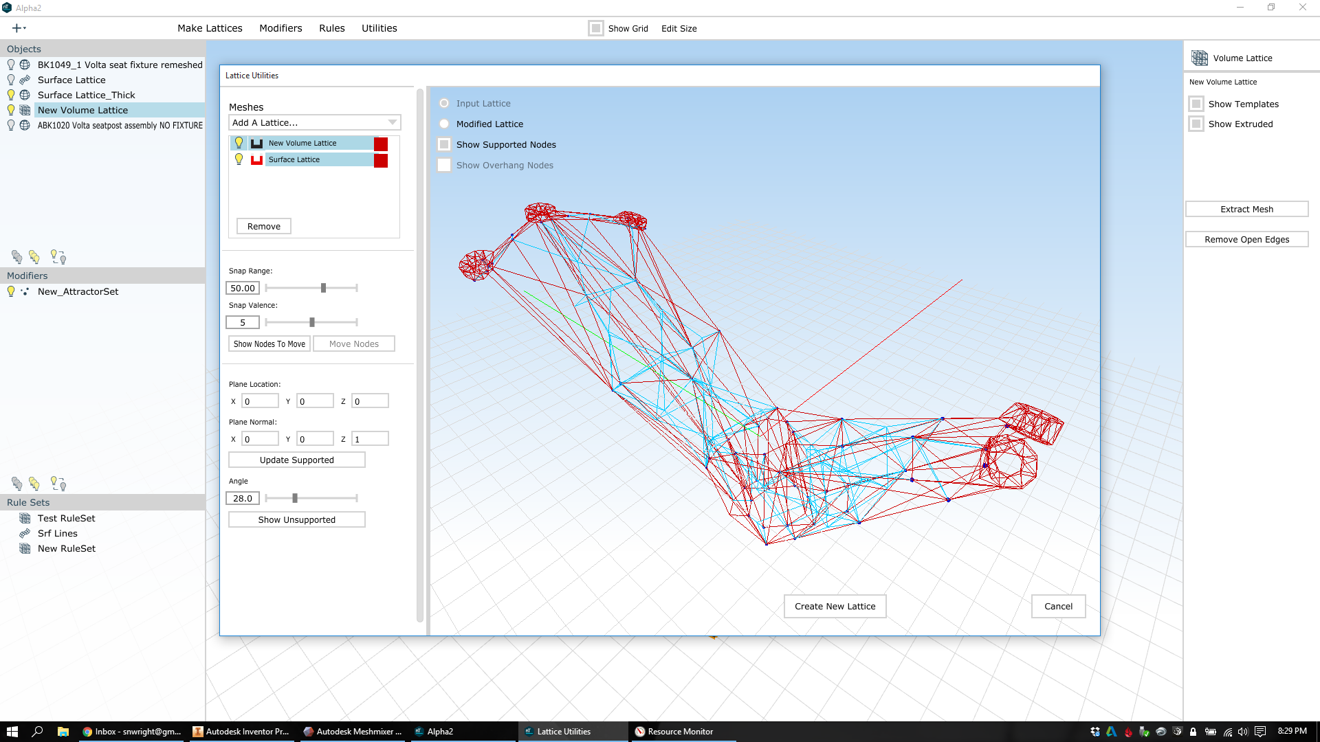
Now I go into the lattice utilities and set the surface lattice as an attractor. I select the volume lattice as the one whose nodes I want to move, increase the snap range to 50mm and valence to 5 (I want basically all of the volume lattice's nodes to move, except those that have 6 connections), and then move the nodes:

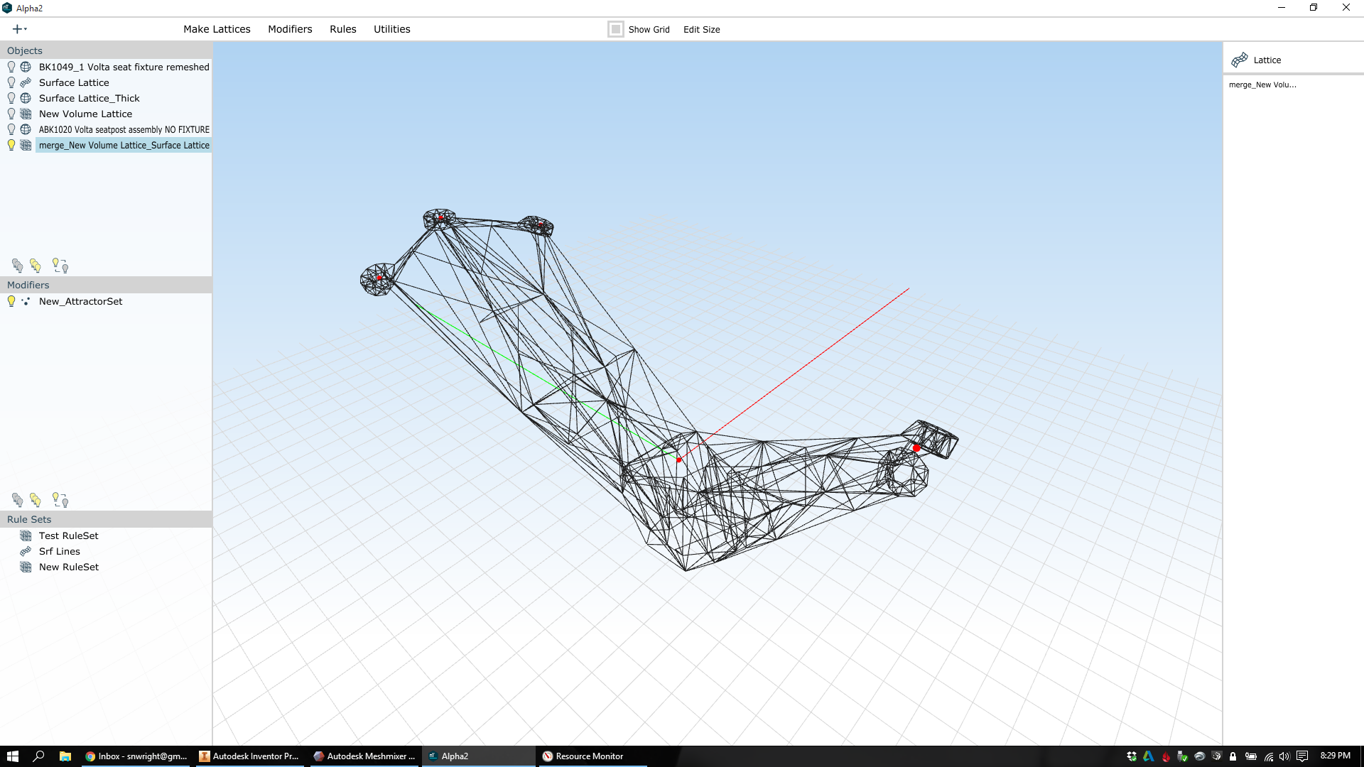
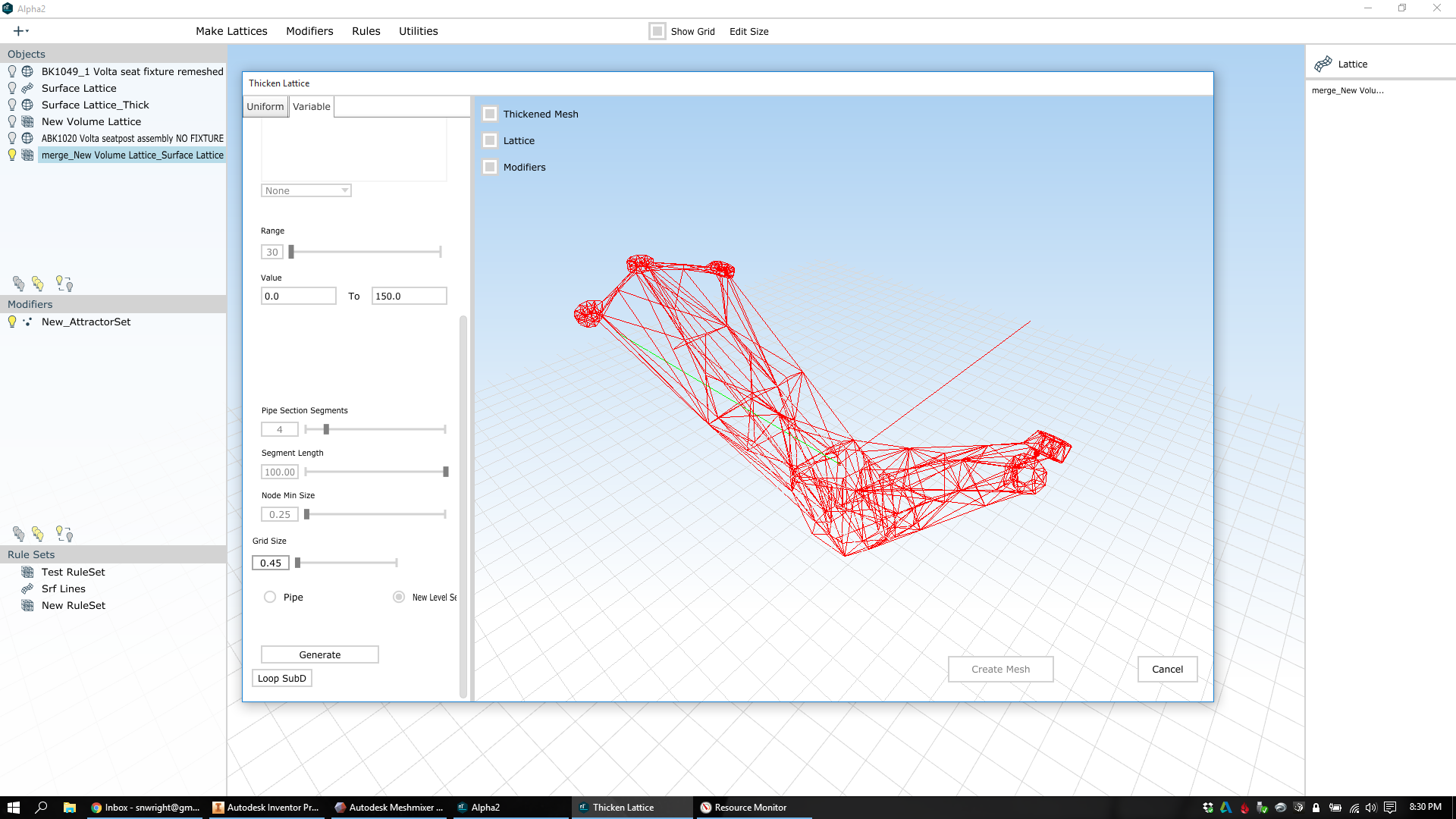
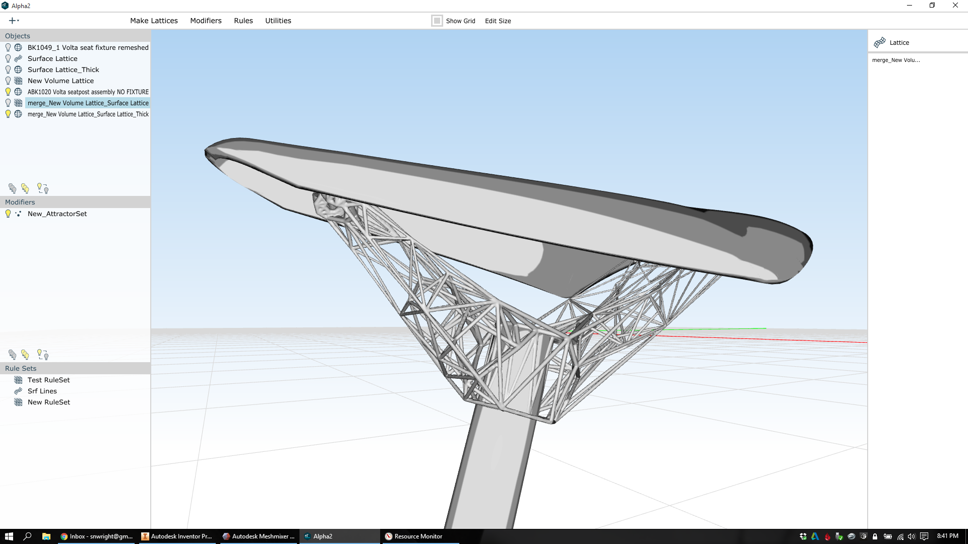
Now I've got a merged structure: A surface lattice and a volume lattice, and they share nodal connections so the whole thing is tied together. I'm ready to thicken the lattice and see what it actually looks like. As before, I've added attractors in the areas where the design has mechanical features. I set the thickness range from .5mm to 1.2mm, and let it run:
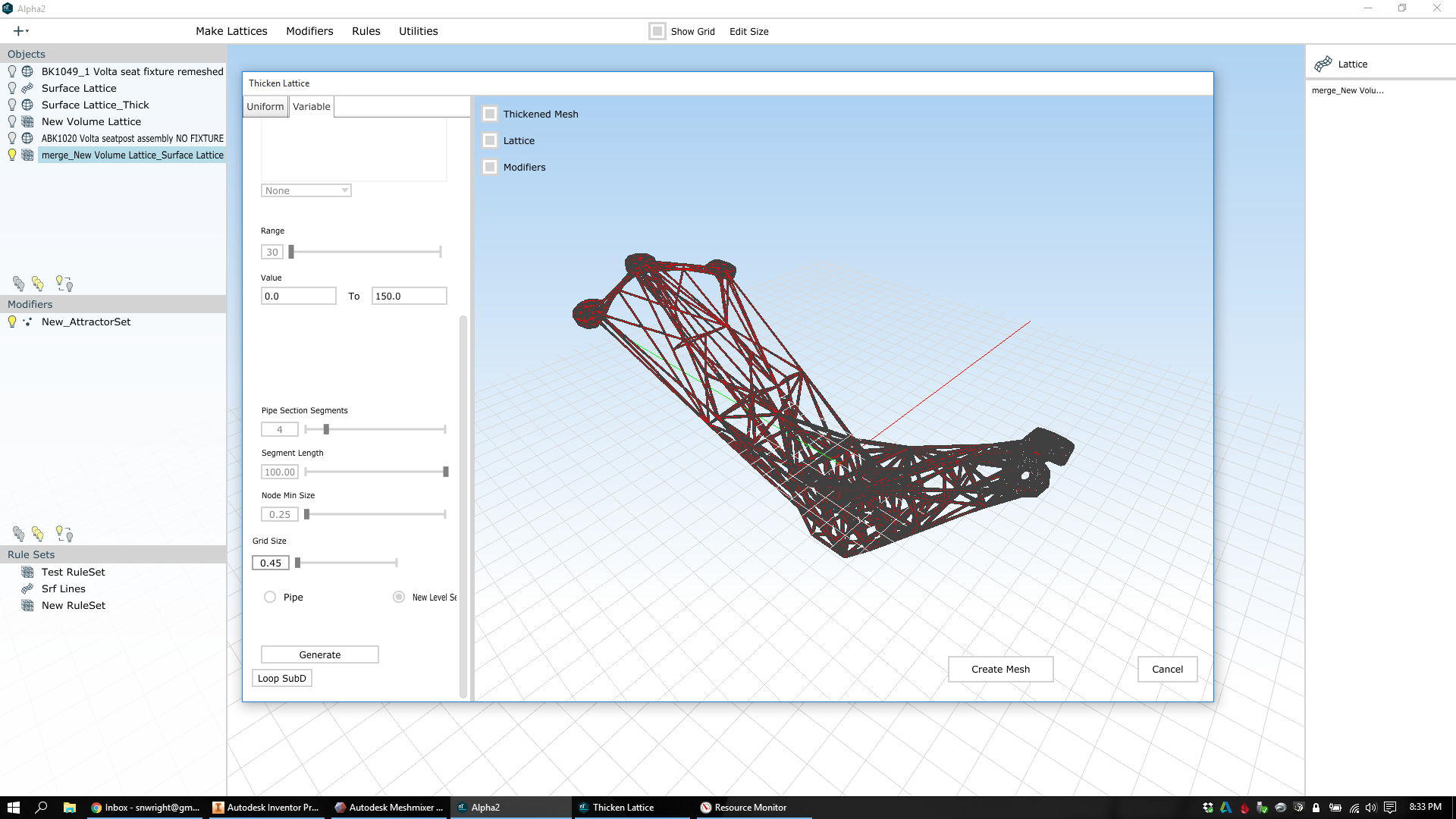
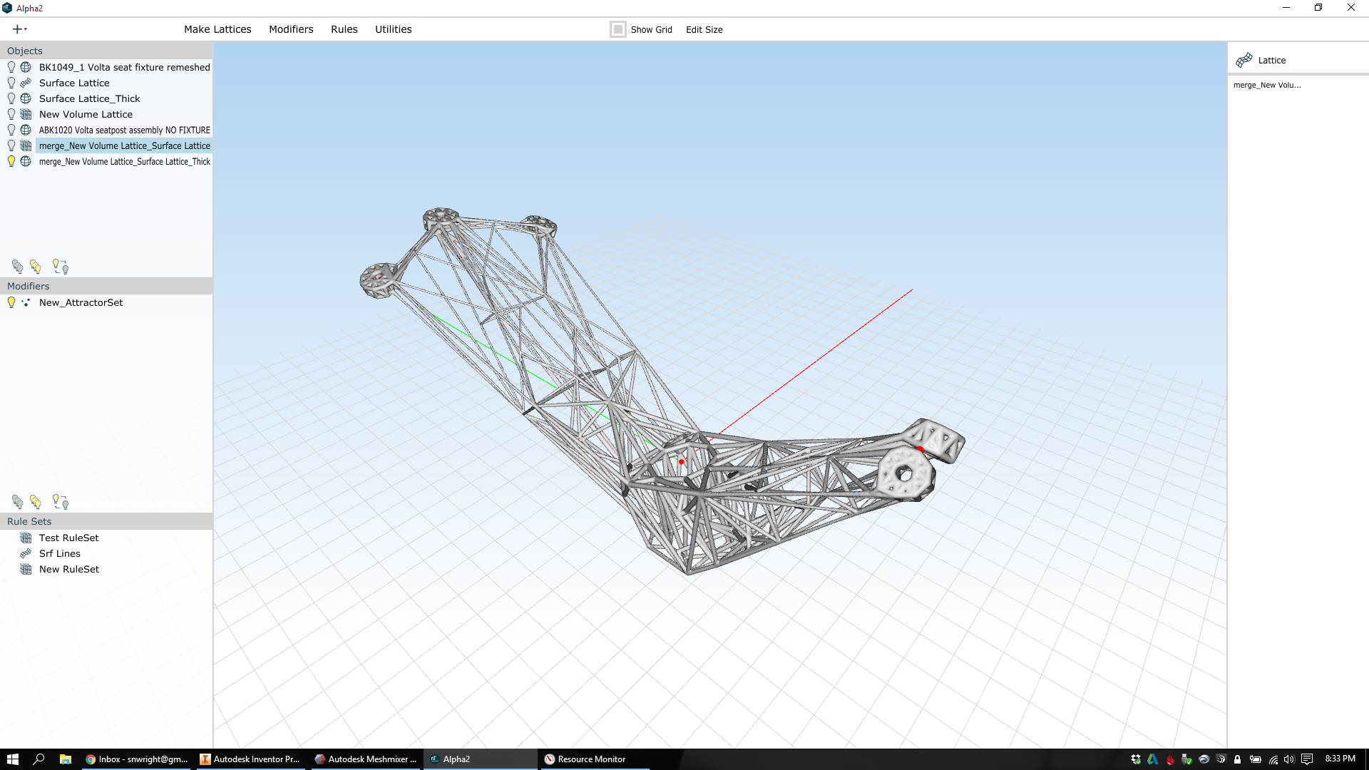
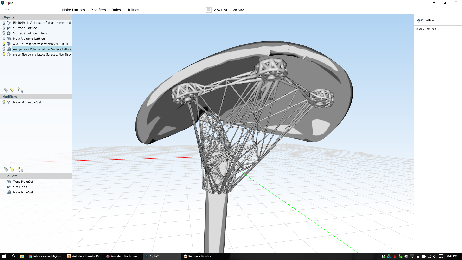
Here, you can see both the internal and external structures:
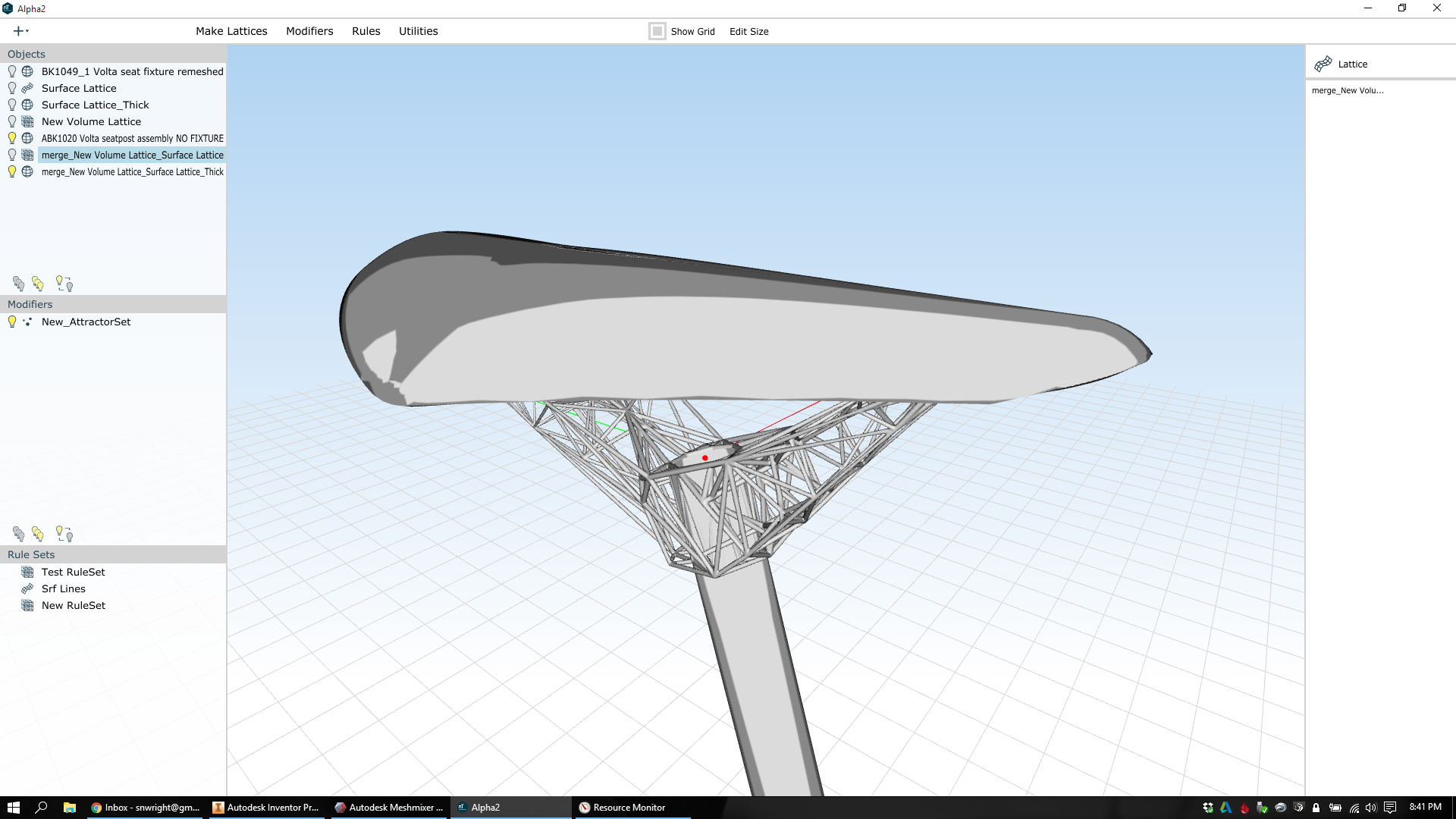
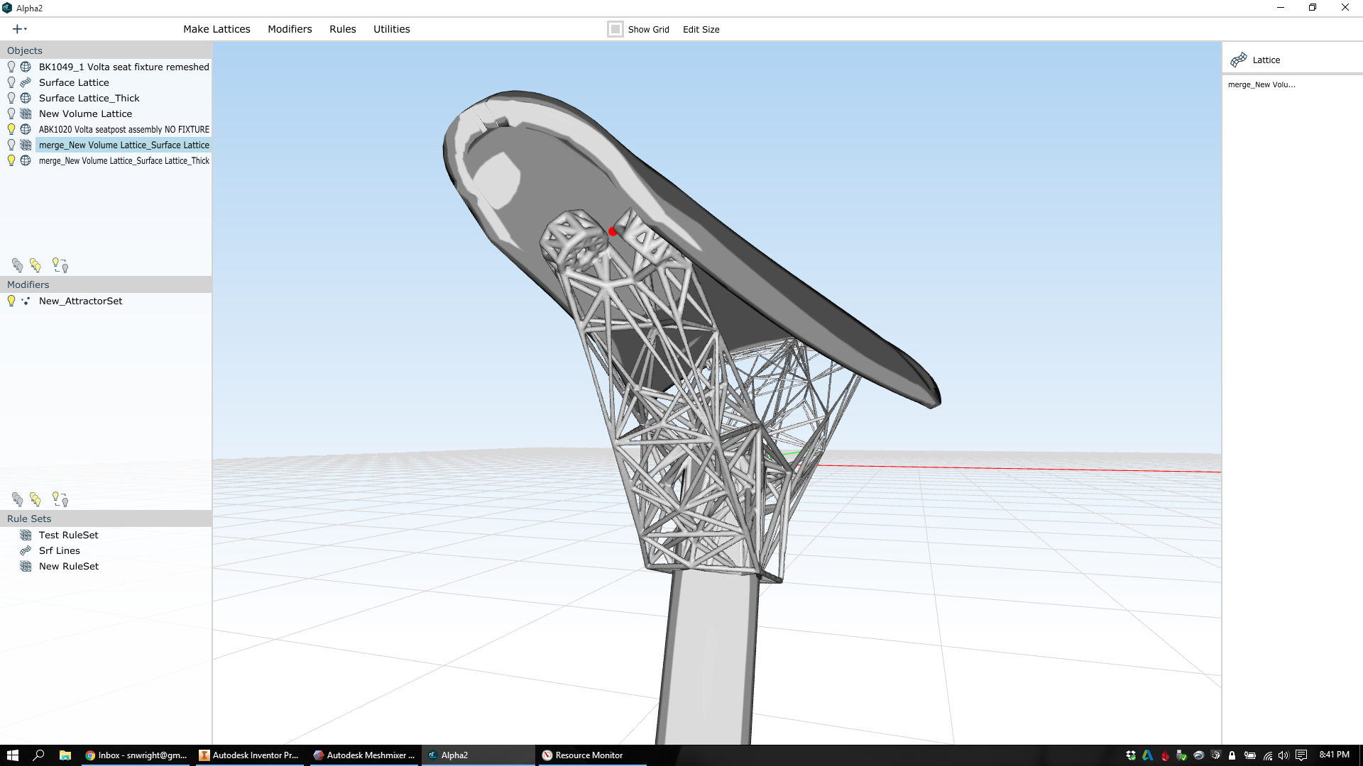
And here it is with the saddle and seatpost attached:
As it's designed now, the lattice part is 18141 mm^3. In titanium 6/4, the weight of the part is 81.76g.
That's light.
Now, this part still isn't really manufacturable - there are too many overhanging faces. It also hasn't been run through FEA, and its distribution of mass probably needs some adjustment.
But it's a pretty good start :)
More soon.