Manufacturing guy-at-large.

Filtering by Tag: seatpost

EBM and chemical surface finishing

Added on by Spencer Wright.

As I've written here before, the field of high performance surface finishes is fascinating - and complex. Surface finish plays a big role in the mechanical and aerodynamic properties of a part, and (in the case of consumer products) it can have a huge effect on marketability too. And so, as I've gone through the process of developing my titanium 3D printed bicycle seatpost, I've been conscious to evaluate many different surface finishing options to find a manufacturing process chain that's both effective and economical.

And so, this past spring, I reached out to Dr. Agustin Diaz to see how REM Surface Engineering could help my parts.

For a bit of context, allow me to quote myself (from EBM surface finishes and MMP):

The part's nomenclature

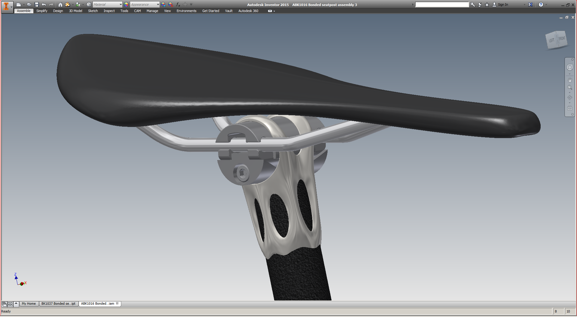
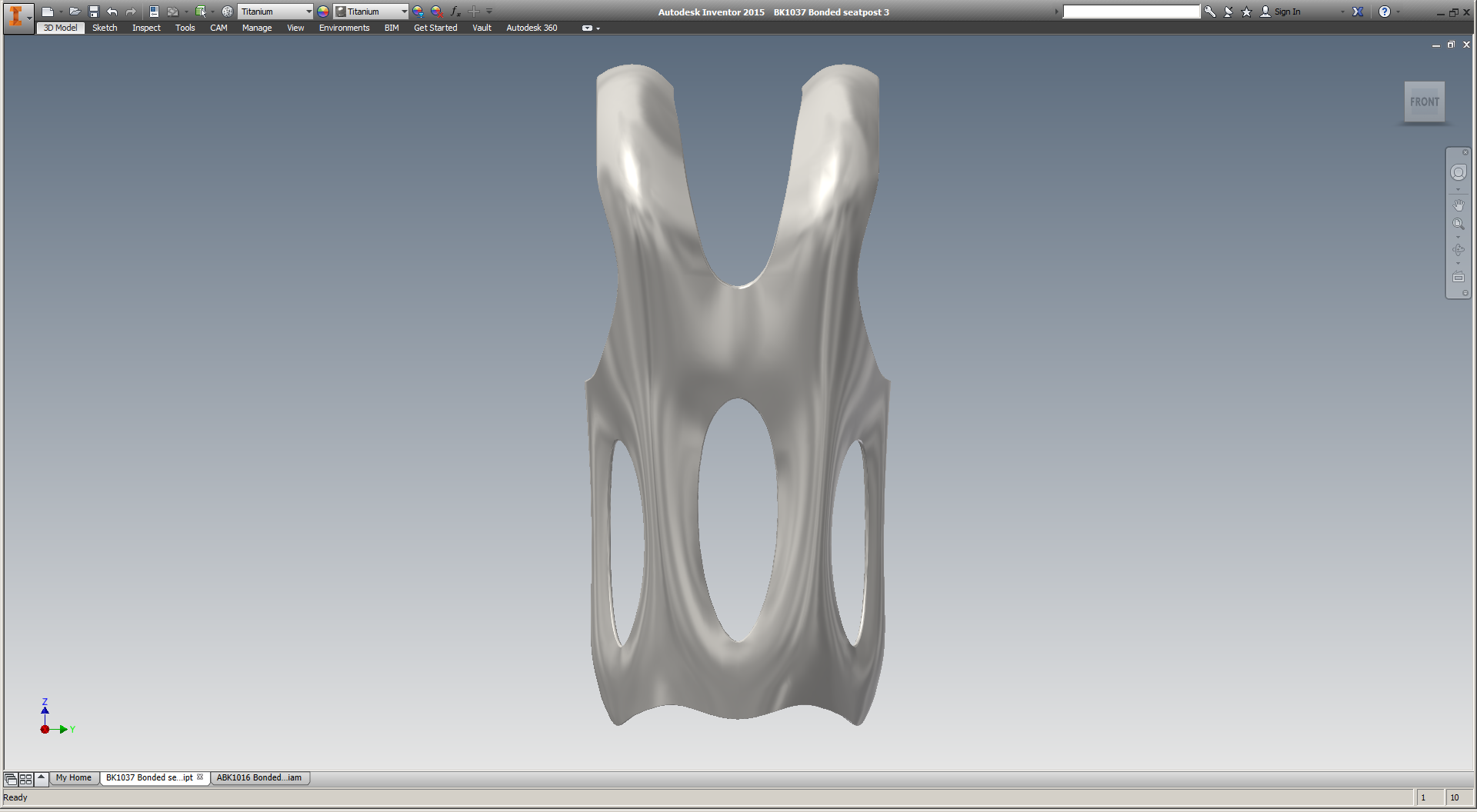
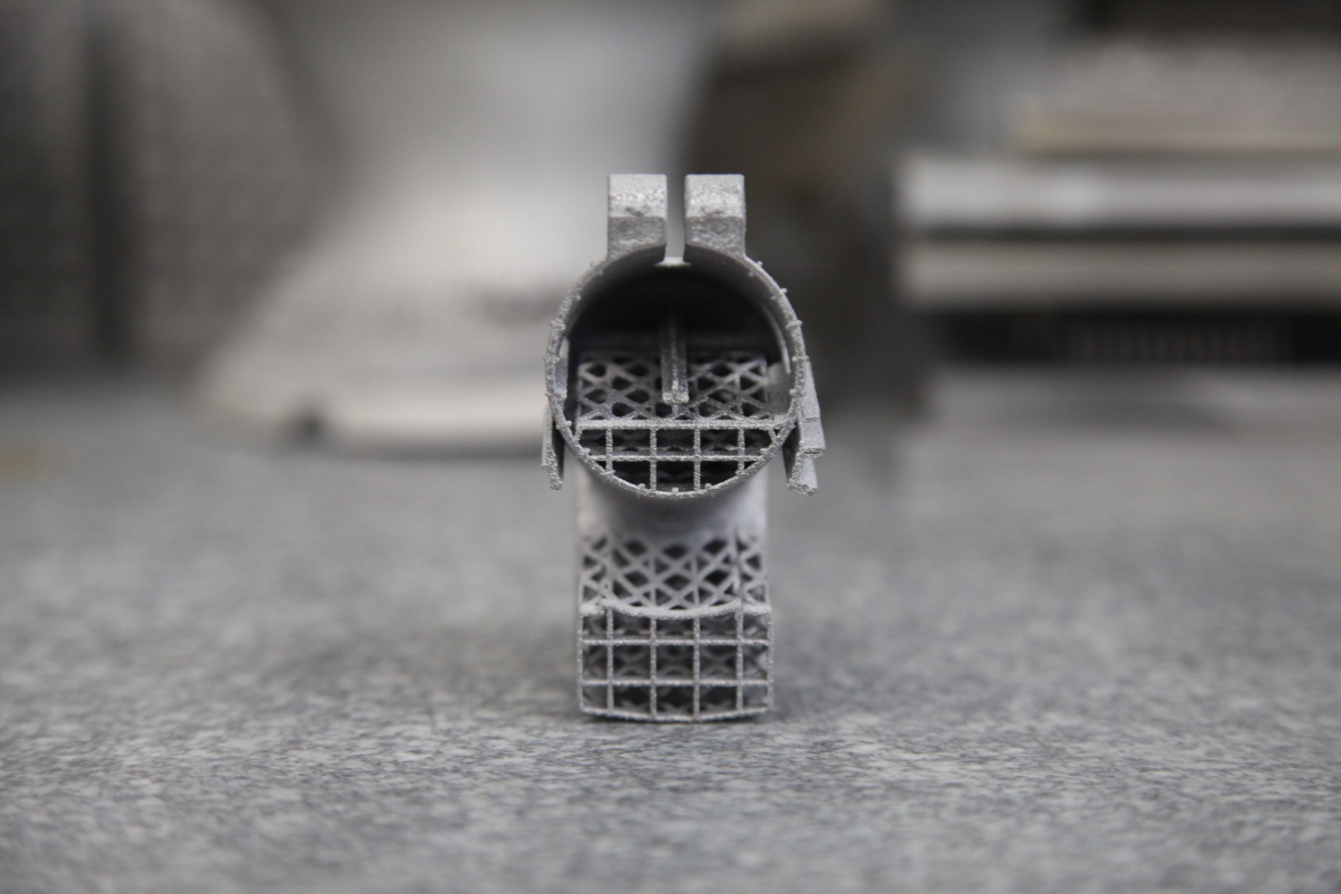
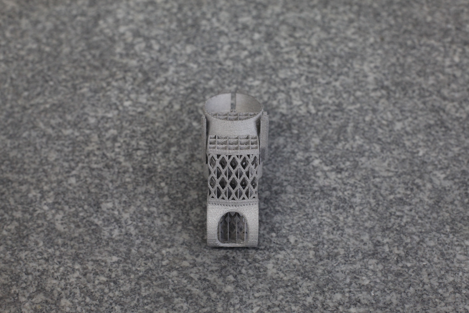
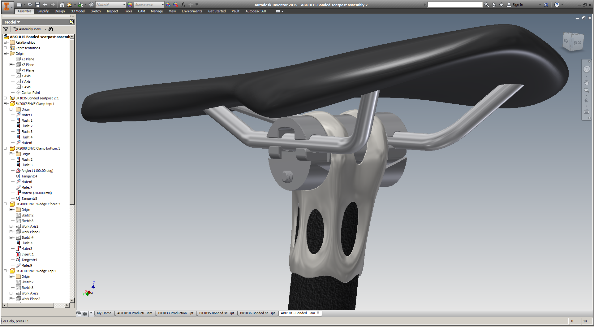
The part in question is the head of a seatpost assembly for high end road bikes. The part itself is small - about 70mm tall and with a 35mm square footprint. As built, it's just 32g of titanium 6/4. Add in a piece of carbon fiber tubing (88g for a 300mm length) and some rail clamp hardware (50g), and the entire seatpost assembly should be in the 175g range - on par with the lightest seatposts on the market today.

As a product manager who's ultimately optimizing for commercial viability, I had three questions going into this process:

  1. How do the costs of the different manufacturing process chains compare? 
  2. How do the resulting parts compare functionally, i.e. in destructive testing?
  3. Functionality being equal, how do the aesthetics (and hence desirability) of the parts compare?

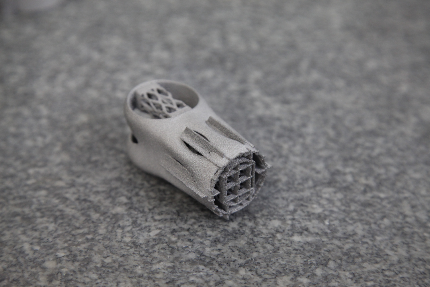
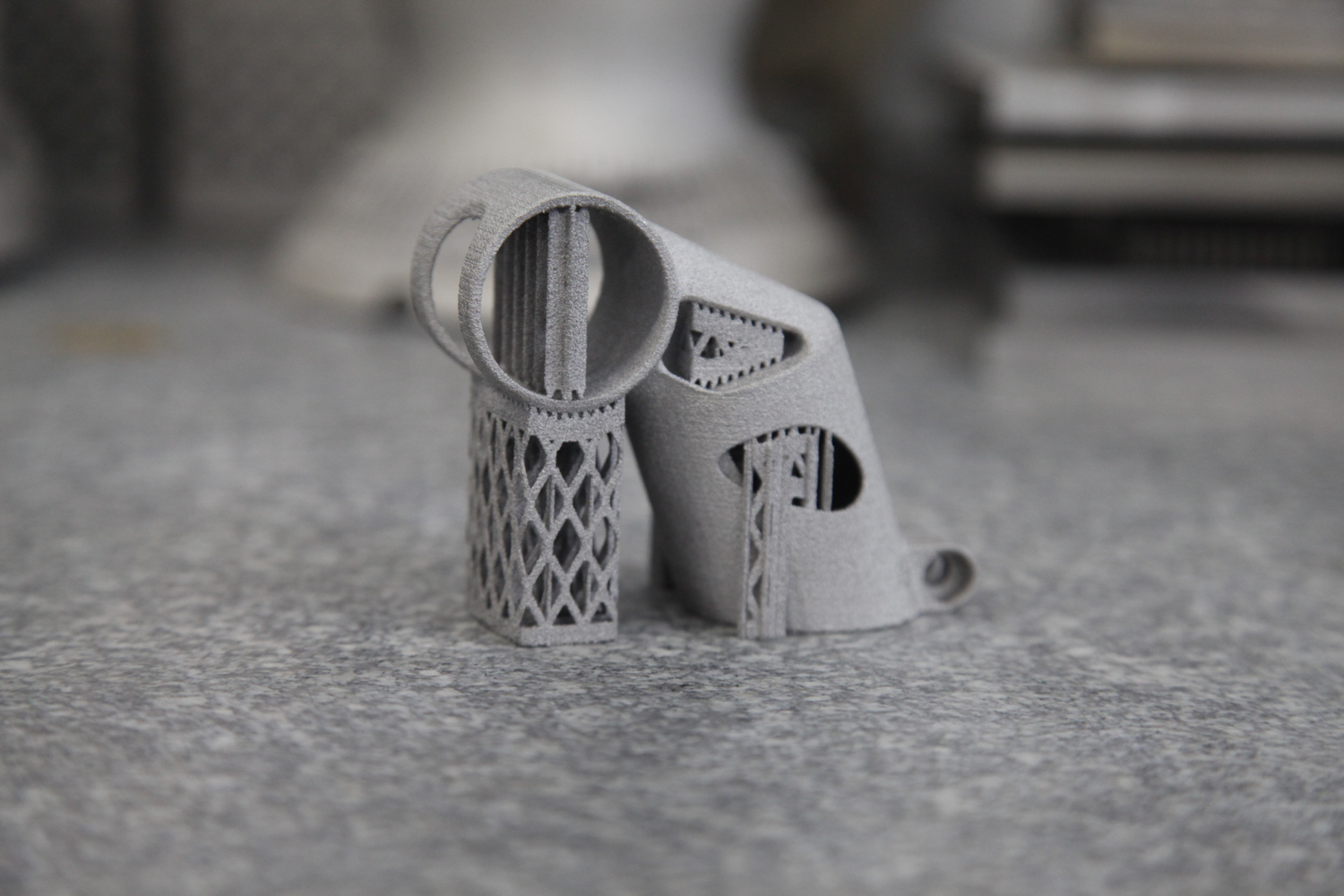
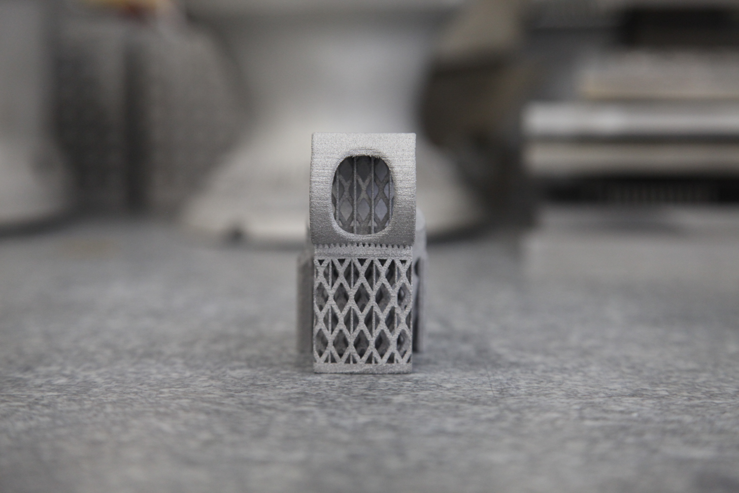
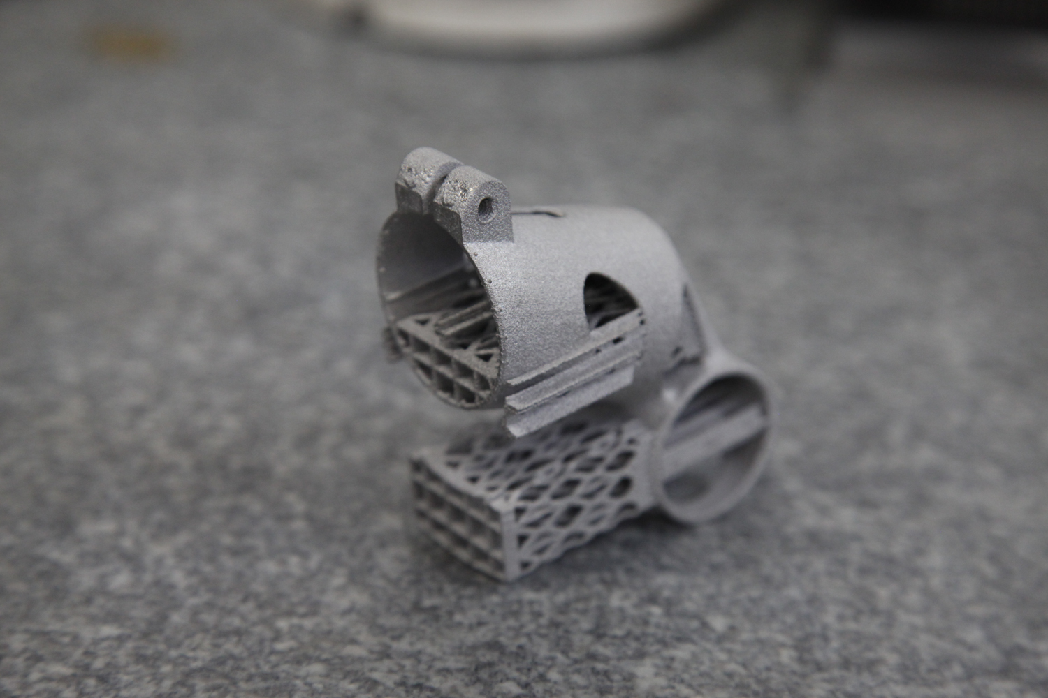
Towards these ends, Dr. Diaz and REM finished three parts for me:

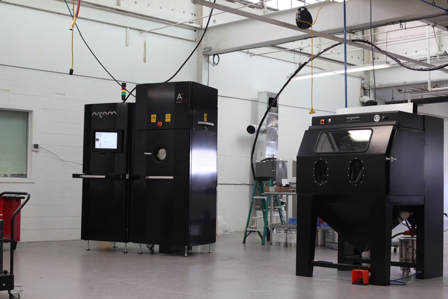
The parts were printed in titanium 6/4 on an Arcam A2X by Addaero Manufacturing. They were then HIP'd (hot isostatic pressing is a whole other area of interest - more on it soon, I hope) before being treated by REM's isotropic superfinishing process.

The results are very interesting, and contrast in many ways with MicroTek's MMP process. REM ISF is a chemical accelerated vibratory finishing process. In it, parts are placed in vibratory finishers with a nonabrasive media and a chemical activating agent. The chemical agents are selected by the part's composition: Different metal alloys will react to different chemicals. The media, on the other hand, is selected depending on the part's geometry: Parts with small features will require smaller media, etc.

As with any vibratory finishing process, then, REM tunes the frequency and amplitude of the machine to adjust the aggressiveness of material removal. The media chambers in these machines are shaped like toruses, and parts take a rotating helical path around them as they vibrate. Adjusting the frequency and amplitude of the vibration affects that helical path, and REM tunes the rolling angle to produce the result that's needed. "It's an art and a science," Dr. Dia zaddtold me.

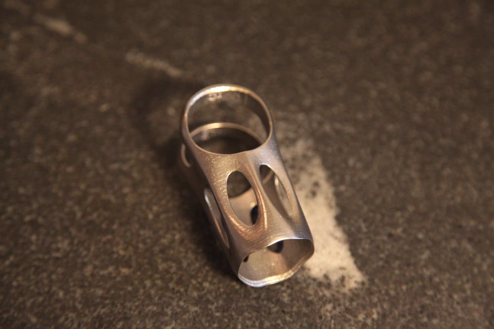
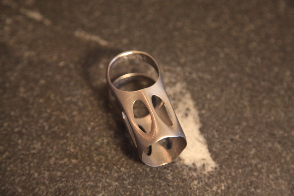
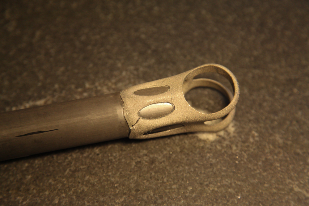
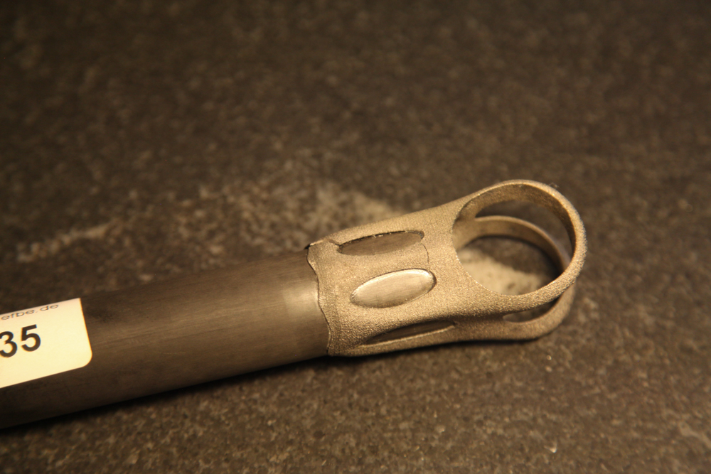
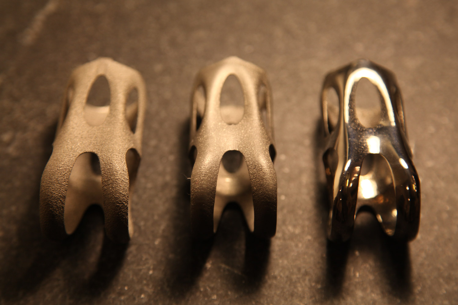
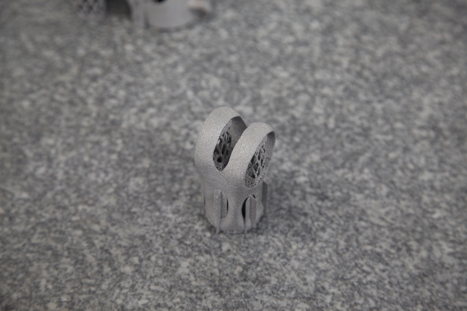
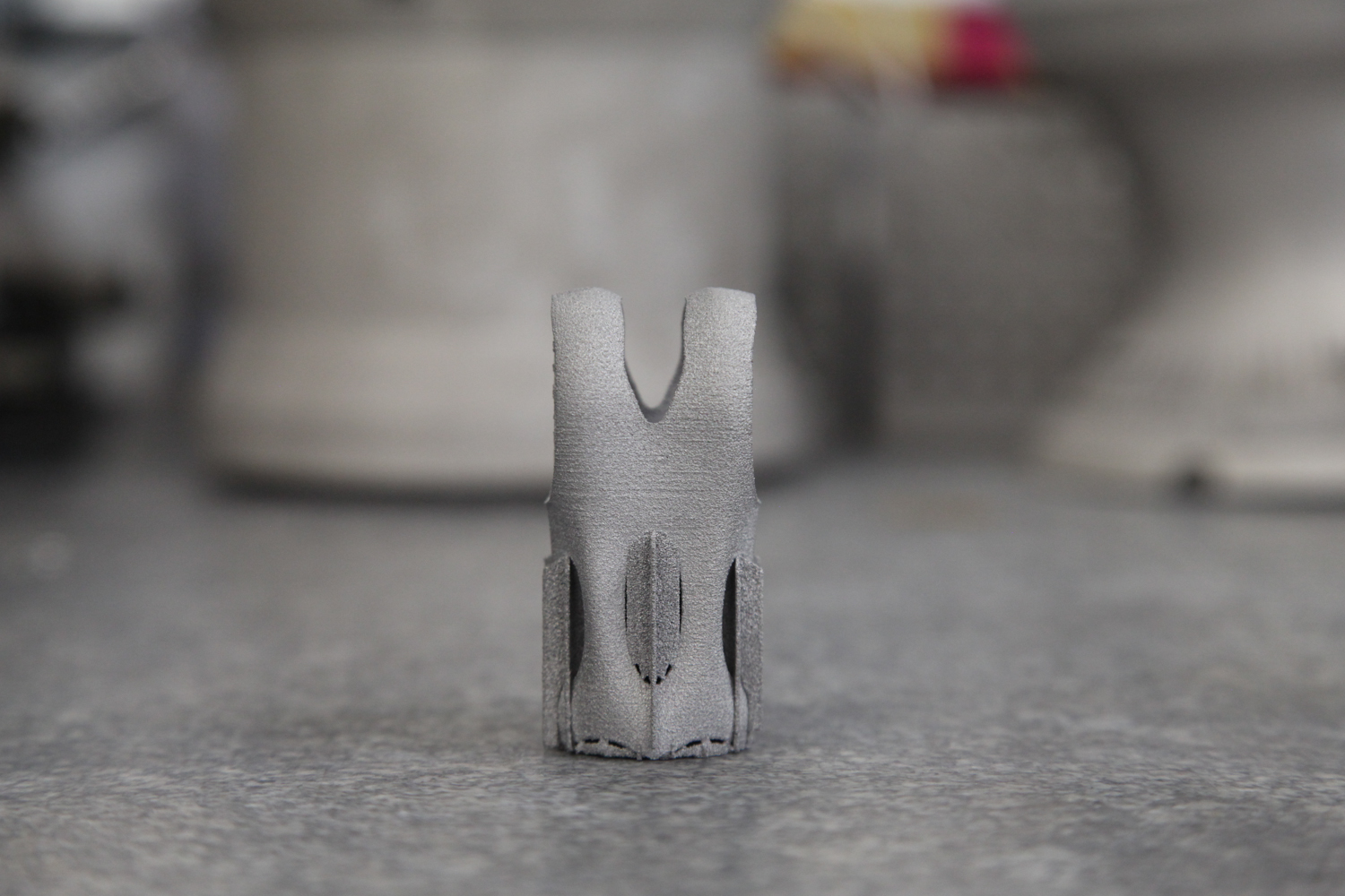
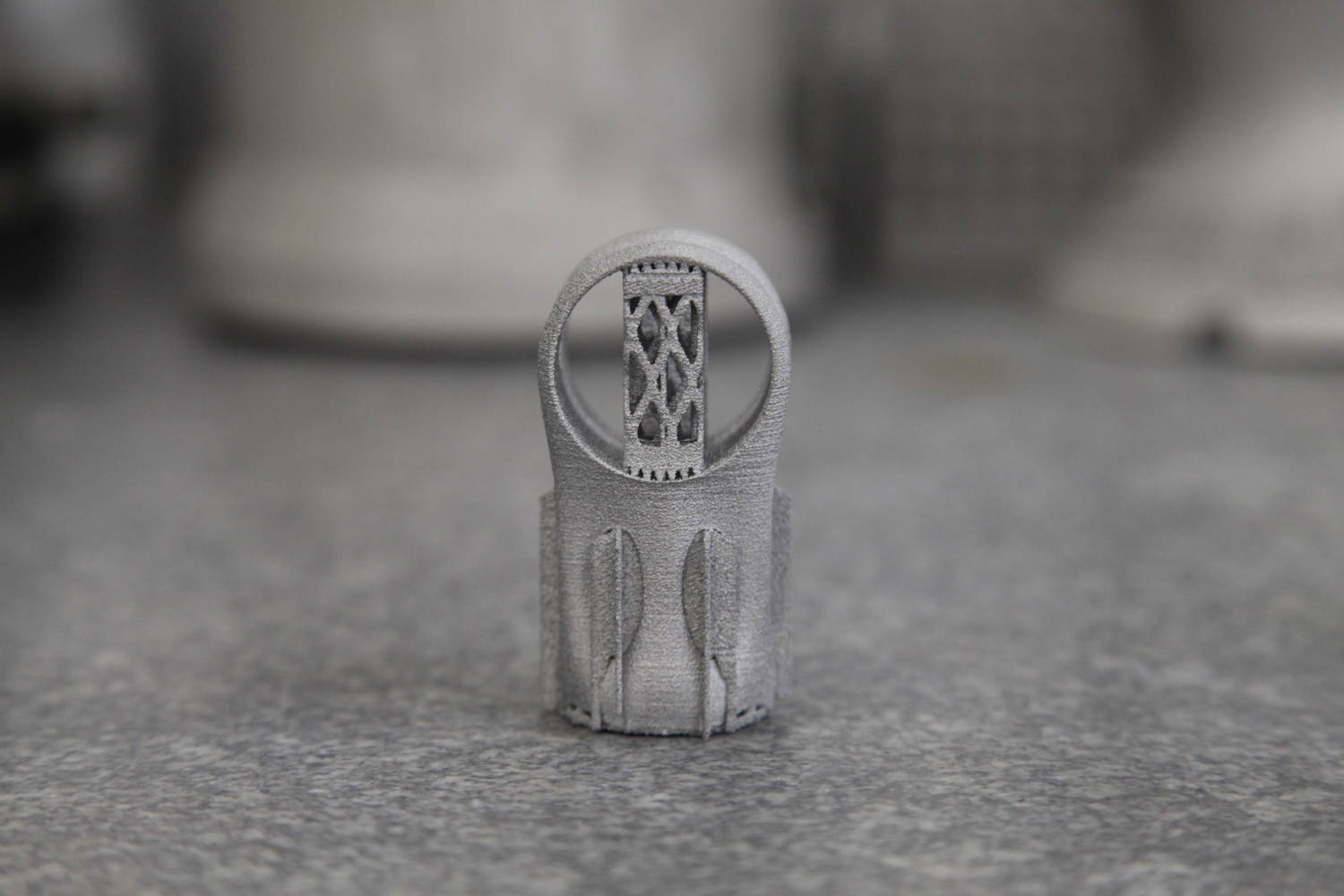
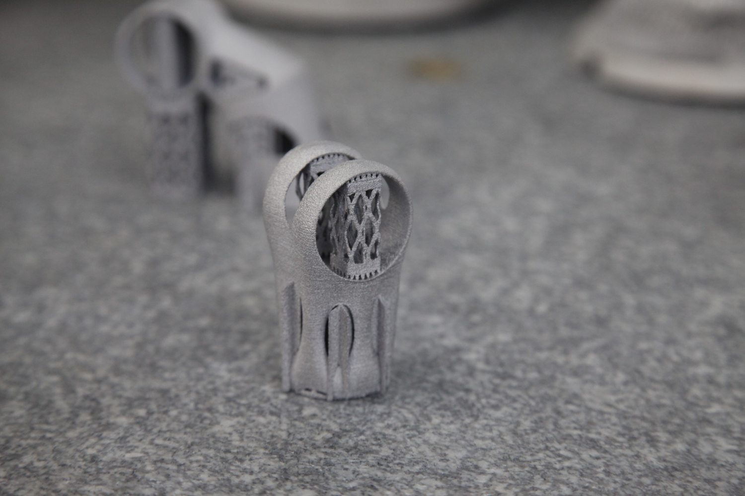
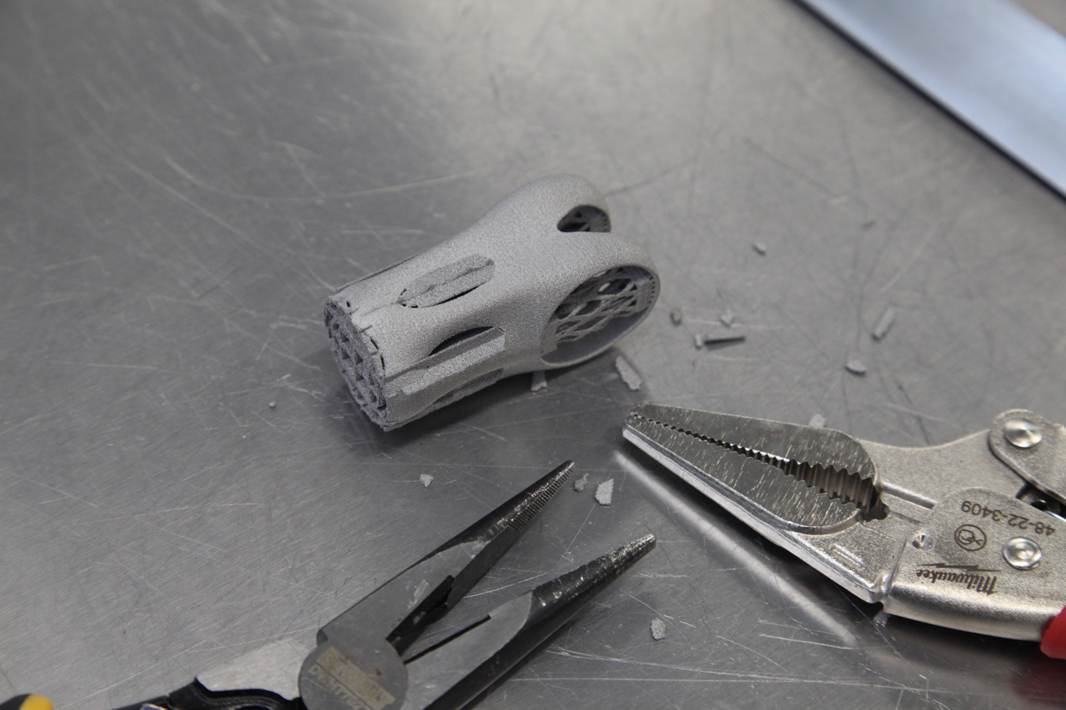
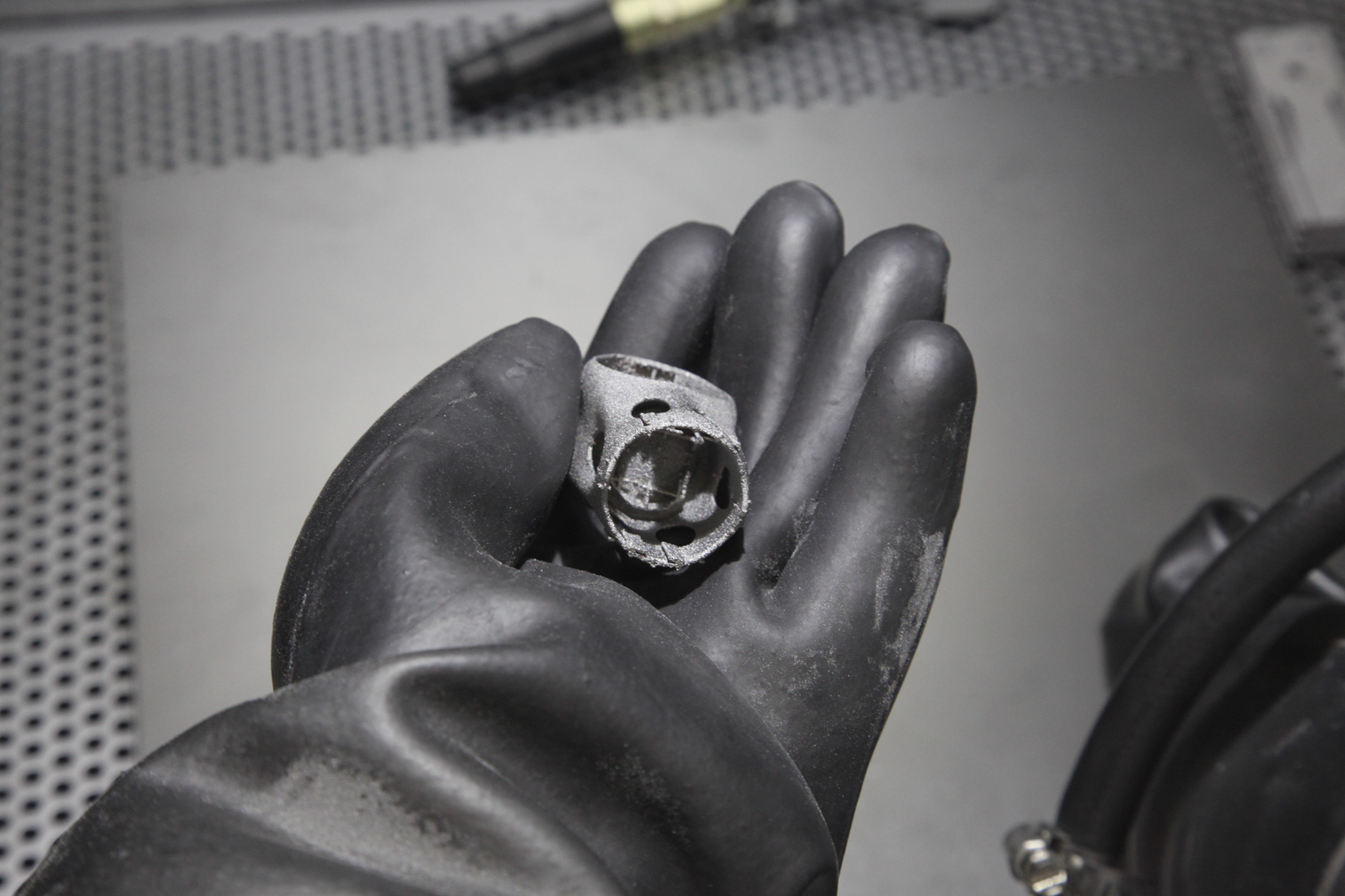
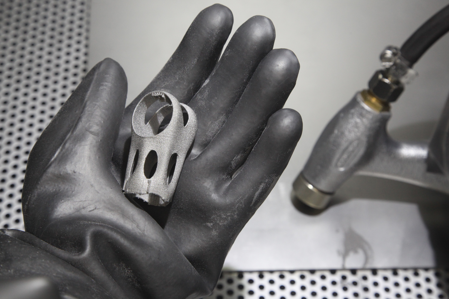
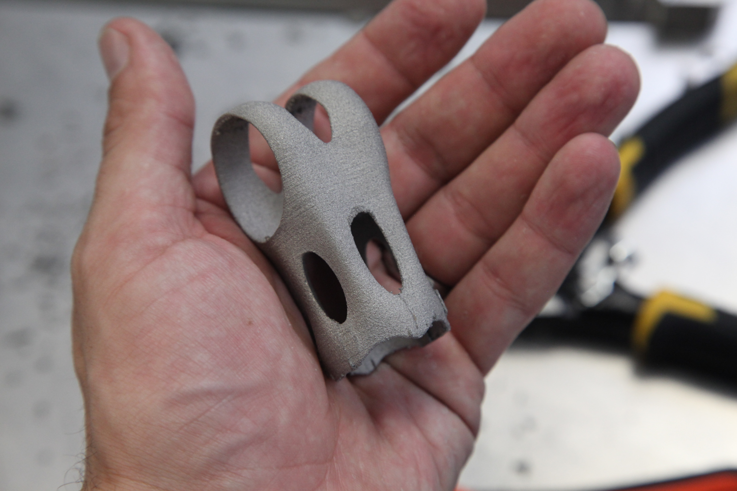
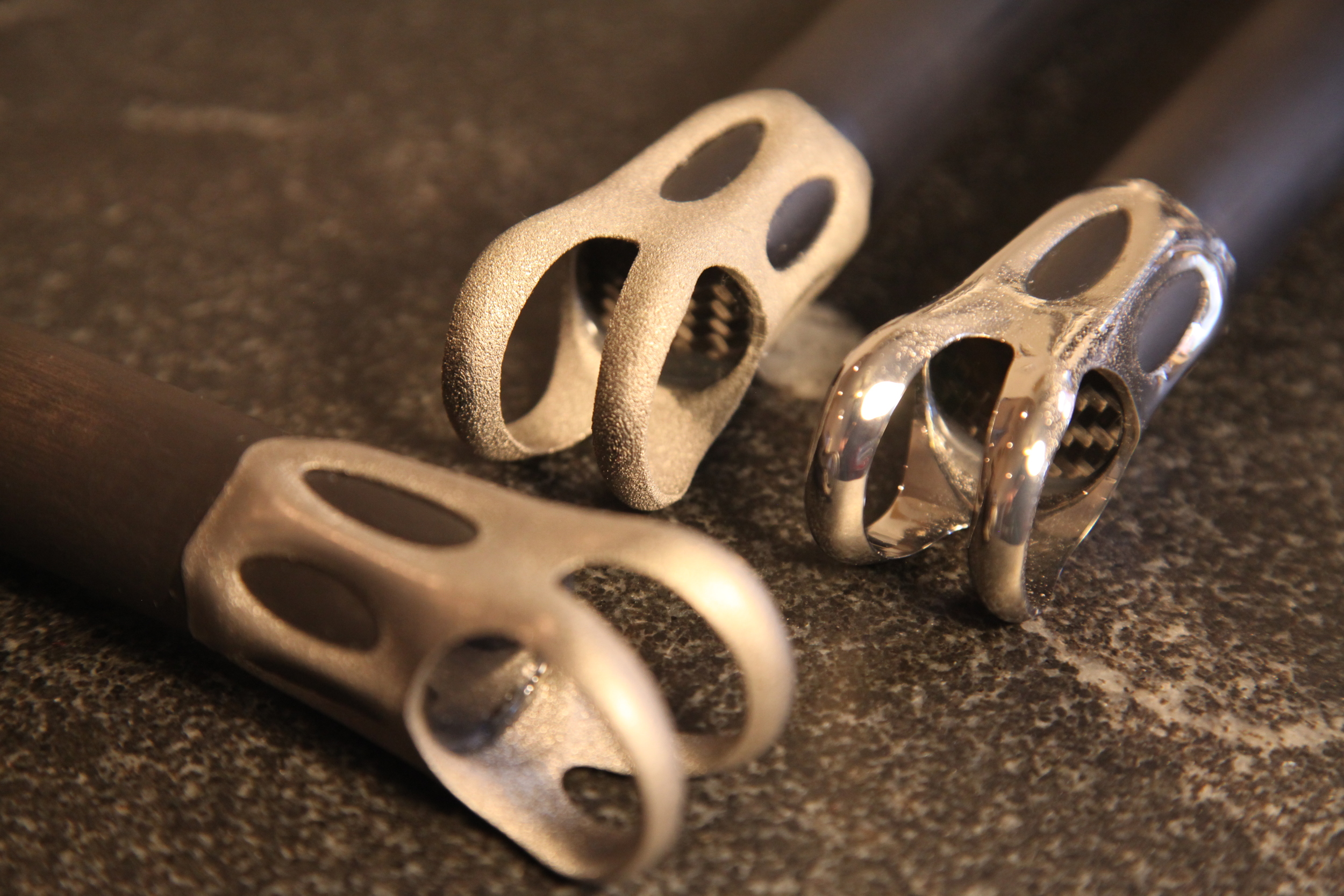
REM finished three parts for me, in two slightly different design variations. The first part went through their Extreme ISF process - a quick treatment that removes excess powder and some higher-order roughness. The second two parts went through Extreme ISF *and* an additional ISF treatment, removing .020" (about .5 mm) and producing a much smoother surface. In order to compensate for the material removal, one of the Extreme ISF + ISF parts was printed with .020" of  extra stock on all of its surfaces (if you look closely, you can see the additional stock as a stair-stepping effect on the inside of the skirt edge). The results are below - click on the photos to enlarge.

Incidentally, I found REM's process nomenclature a bit confusing at first. As described above, all of these processes include some chemical agent and some media. The difference in the different processes has to do with the balance of those two factors: Extreme ISF uses aggressive chemistry but relatively little media interaction, whereas ISF is a longer process with less aggressive chemistry and more media interaction. REM also offers a Rapid ISF process, which is to ISF much as a lathe is to a milling machine. In it, the parts are fixtured and then moved through the chemical/media mixture. It's a much faster process, but one which requires more tooling and setup and hence is reserved for high volume parts.

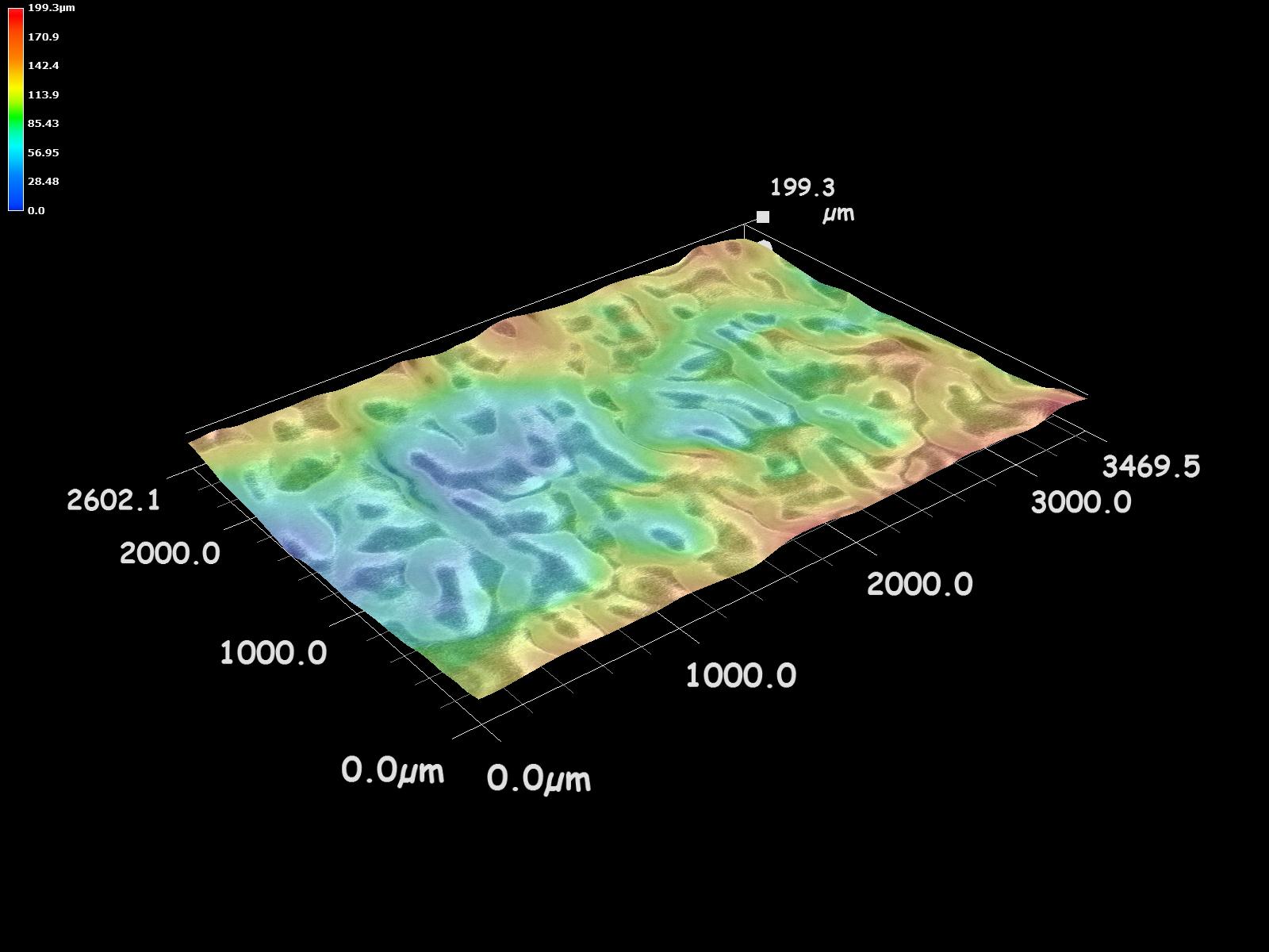
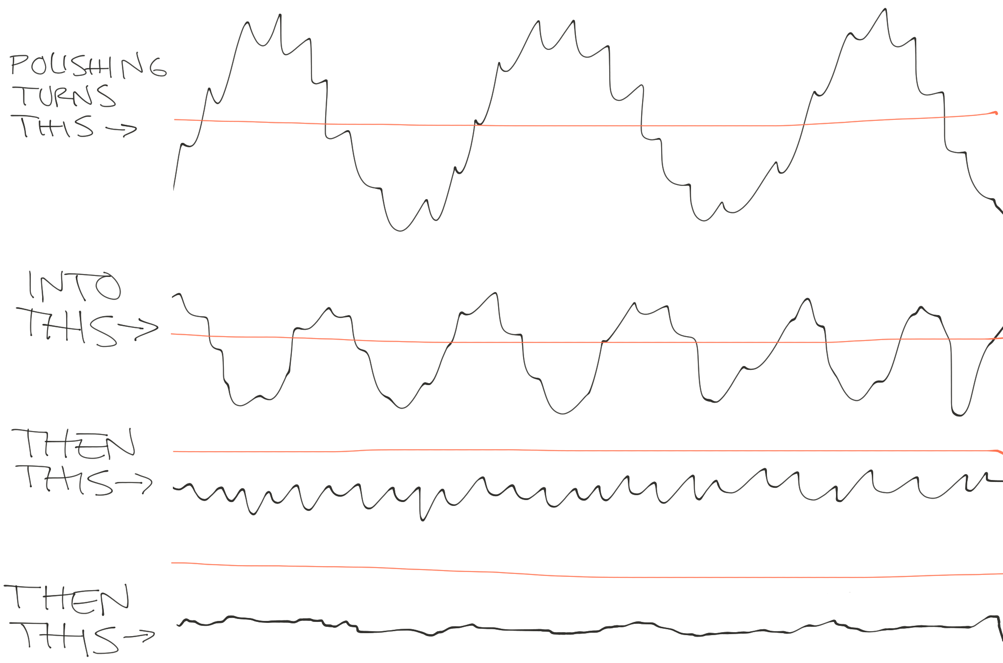
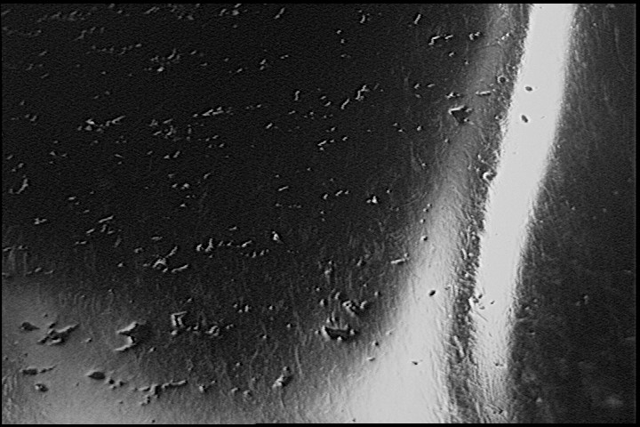
The surface character of the REM parts differs significantly from the parts that I had MMP'd. ISF interacts with the full surface of the part, with the result being that both peaks and valleys are rounded out. Note that the color scale in the images below are not constant; click on the images to see the color scale key.

The roughness values for the two methods are also quite different. The key metrics are below; full roughness profiles & filter data are here for Untreated, Extreme ISF, and Extreme ISF + ISF parts (thanks to REM).

Ra - Roughness average

All values in µm. Evaluation length = .5"

Rq - Roughness, root mean square

All values in µm. Evaluation length = .5"

Rsk - Roughness skewness

All values in µm. Evaluation length = .5"

Rt - Roughness total

All values in µm. Evaluation length = .5"

As with most things, the numbers above both a) capture interesting differences between these five finishing methods, and b) are abstractions which ultimately fail to capture the entirety of the physical parts. Such is the nature of data; in and of itself, it's not particularly insightful.

As I've described previously (and above), my interests are functional, aesthetic, and economical. The latter two of these sit more or less in balance, but the former is bound by the composition & arrangement of matter. To that point, Agustin referred me to a paper by Kwai Chan called "Characterization and analysis of surface notches on Ti-alloy plates fabricated by additive manufacturing techniques," which shows a correlation between notch depth and a shortened fatigue life in EBM parts. To quote:

The presence of surface notches is likely to promote crack initiation and reduce the fatigue performance of LBM and EBM materials. Since the depths of the surface notches correspond to the maximum valley depths on the surface, fatigue life of the various Ti–6Al-4V materials is expected to decrease with increasing maximum Rvm values...
To improve fatigue performance, the surface notches on the EBM and LBM materials must be removed by machining.

Of course, those last two words - "by machining" kind of begs the core question that I'm asking here. To wit, see the Rvm numbers from REM:

Rvm - Maximum valley depth

All values in μm. Evaluation length = .5".

The goal, here, is to improve fatigue life - and avoid the fate that my last parts met during testing. My hope - and one that's balanced by my lingering concerns about my glue joint design - is that the much reduced Rvm numbers here will help significantly.

More soon.

Seatpost testing post-mortem

Added on by Spencer Wright.

This week I got my seatposts back from testing at EFBE. As you'll recall, these failed ISO 4210-09:2014, 4.5.2. 

The part's nomenclature

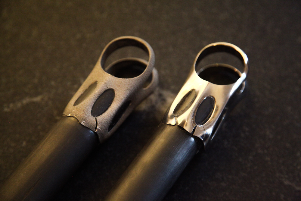
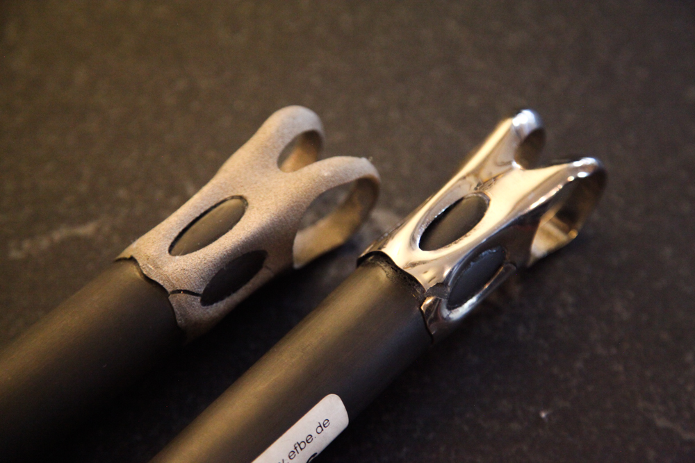
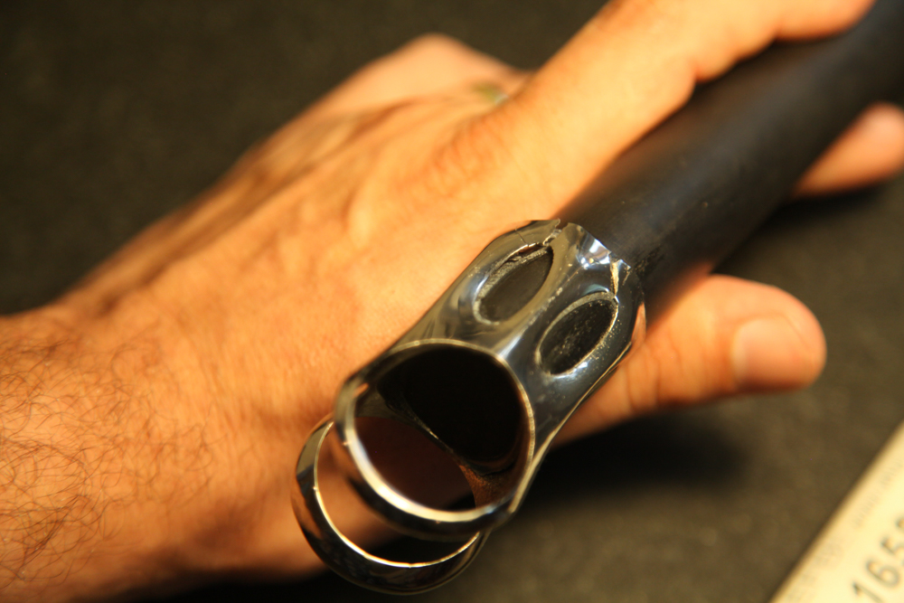
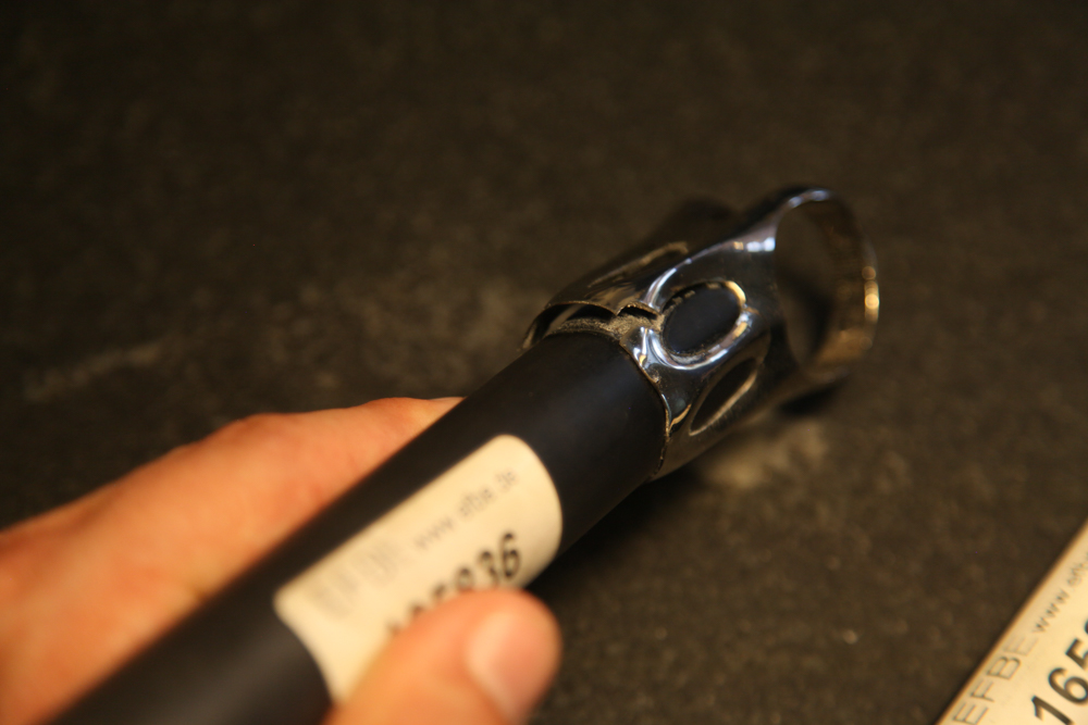
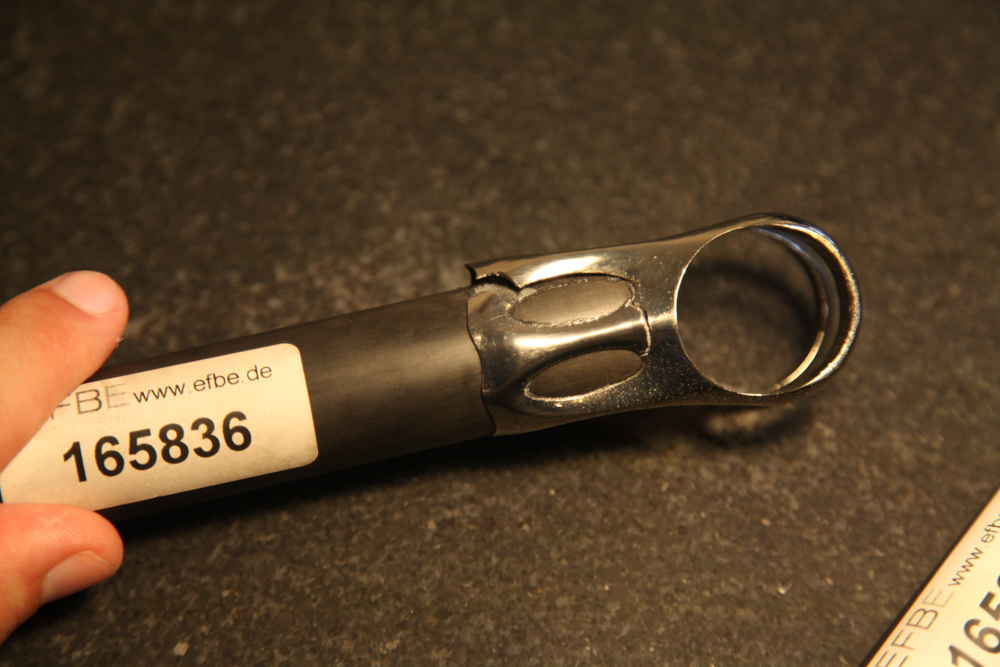
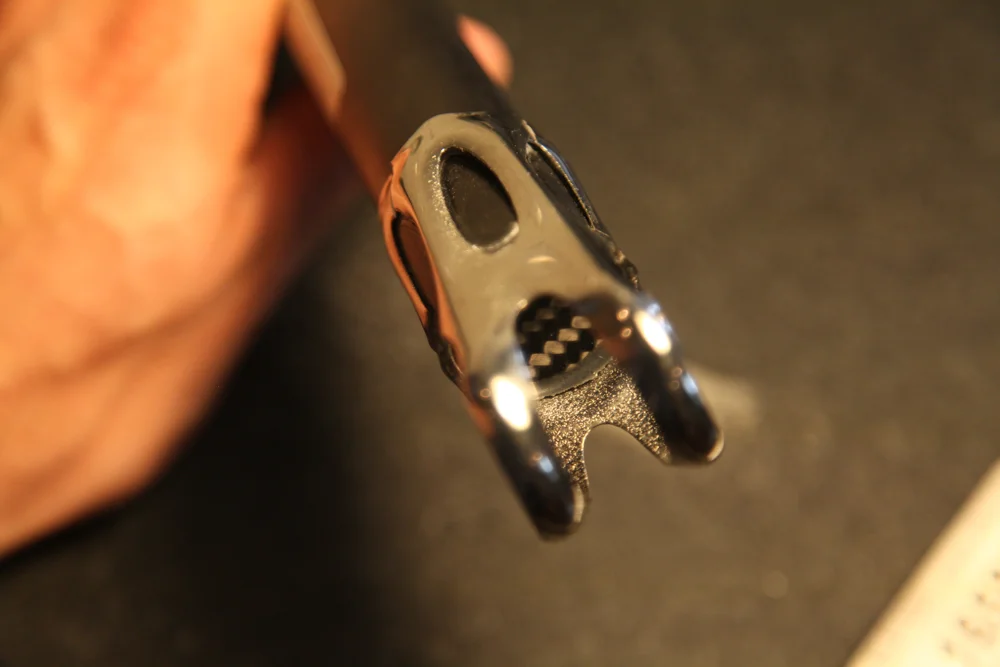
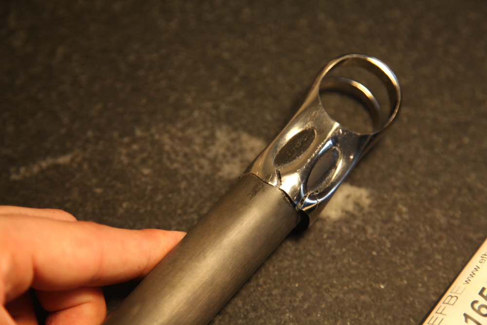
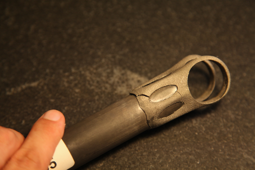
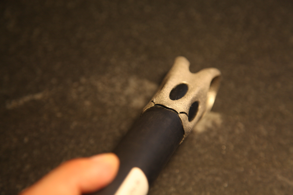
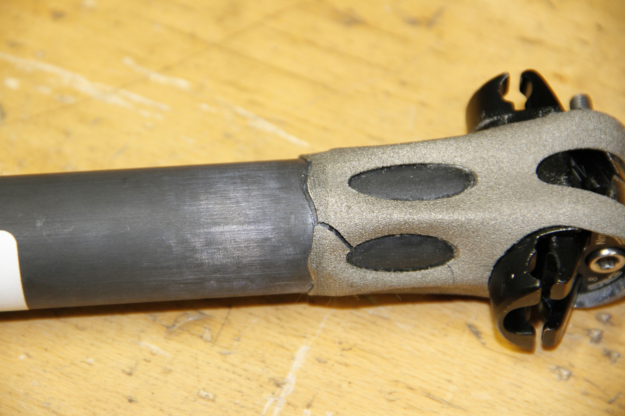
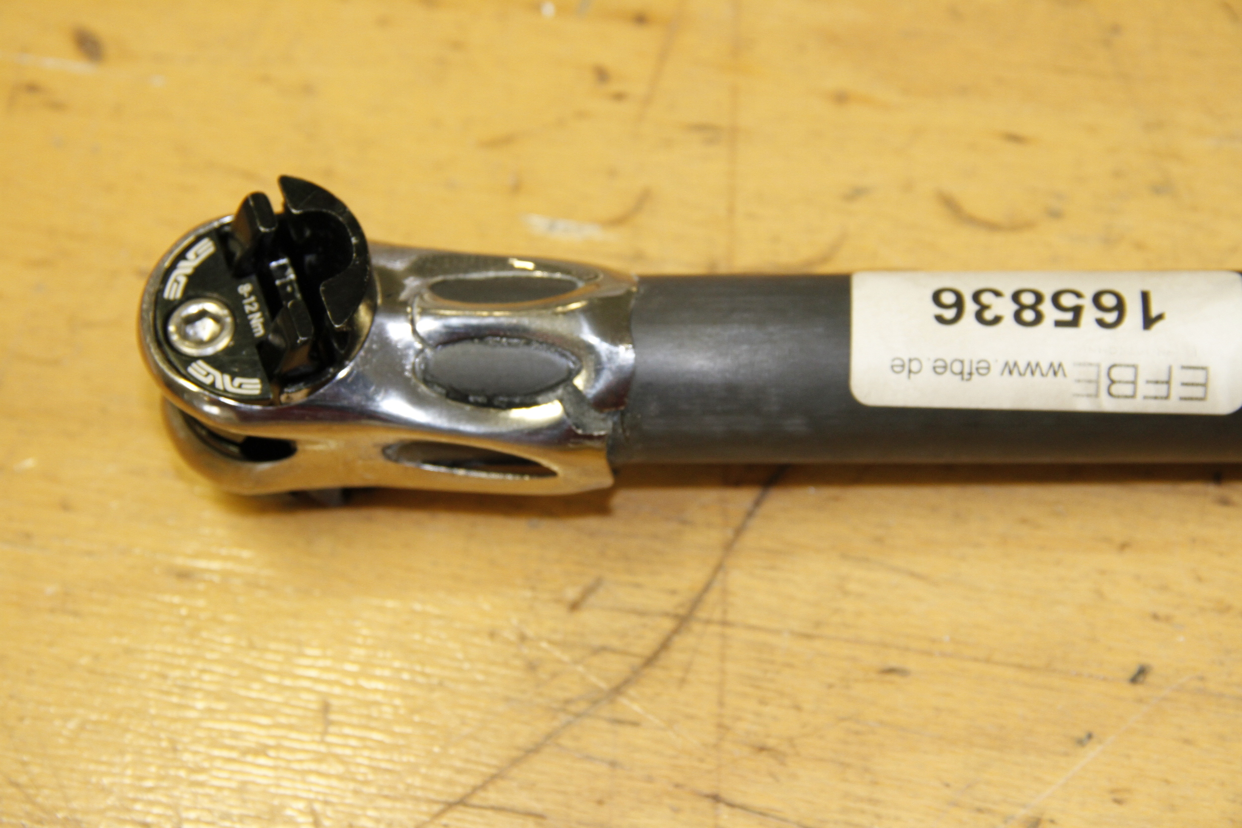
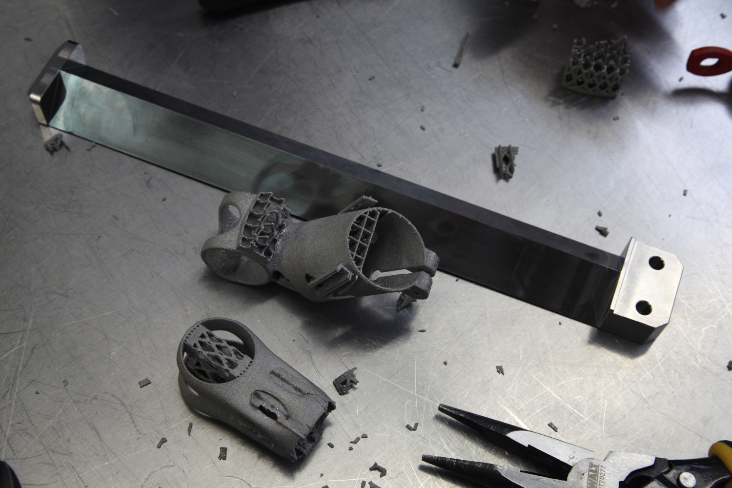
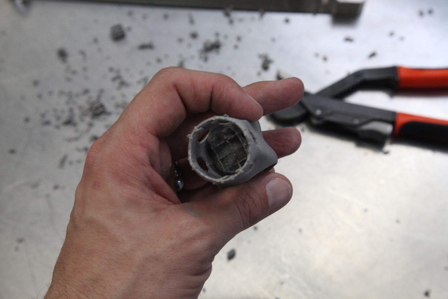
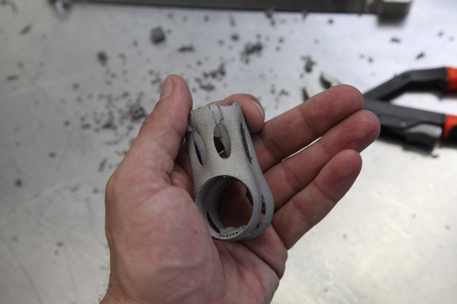
Both seatposts failed in essentially the same way: The shoulder straps rotated backwards, breaking the skirt in two locations and cracking both of the side legs as well. The front of the skirt separated completely from the carbon fiber post at the bottom, and the top/front of the seatpost cylinder appears to have slipped upwards (sheared) as well.

The "BLING" part (see this post for details on the difference between the two samples) failed slightly before the as-printed version, at 70,770 cycles. It's a bit hard to tell in the photos, but there are definitely some areas where I didn't have enough glue to form a complete bond. Part of this is operator error (i.e. my fault for not assembling the seatpost well), and part of it is engineer error (i.e. my fault for not designing the seatpost so that it could be assembled by any grease monkey). 

The as-printed part failed a bit later, at 80,904 cycles. Again, close inspection shows that the glueline had many defects.

I take a few lessons from this:

First, it's clear that my assembly design needs to be improved. It's possible that the part still would have failed with a better glue joint, but at this point in my process it's important that I'm able to isolate possible issues - and variations in bond quality makes that *really* hard. I suspect the best approach here is to make the glue cavity captive, such that during assembly the uncured adhesive is forced to fill the full volume between the seatpost head and the carbon fiber post.

This likely means eliminating the windows from the seatpost cylinder. It also means either creating a double lap shear joint (like Robot Bike uses) or making the joint blind on both sides (by capping the end of the carbon post, which I did on this assembly, *and* closing the top of the seatpost cylinder, which I didn't do). 

Second, I should probably be HIPing these parts - at least until I've isolated everything else and determined whether, and how, HIP affects performance.

Third, I'd like to dial in the inner diameters of both the seatpost cylinder and the saddle clamp cylinder. The latter can probably tolerate a bit of play, but the former directly affects the glueline and should probably be controlled more tightly.

On the upside: The failure mode on these parts wouldn't have hurt the rider, whereas failure in the shoulder straps could have been dangerous. In addition, I've got a chance to try this again - with the parts that REM treated for me recently. I won't be able to change the original design at all, but I can at least try to see whether a change in technique can improve the glue joint.

Regardless, it's good to get tested parts back. More soon!


Note: Thanks to Addaero Manufacturing for printing these parts, and to MicroTek Finishing for finishing them!

Seatposts, tested

Added on by Spencer Wright.

Today I got word from EFBE that two of my EBM seatpost had been tested - and failed.

These are the as-printed and the "bling" samples (see this blog post for details); they failed after 80,904 and 70,770 fatigue cycles (at 1230N), respectively. As a result of their failure, I decided to not test the third "fatigue resist" part.

I'll write up a longer description of the results soon, but two thoughts here:

  • These parts were *not* HIP treated - which might possibly have helped their fatigue resistance.
  • It appears that some delamination occurred between the printed parts and the carbon fiber post, which makes me question whether the glueline itself was faulty. If so, it's possible that by improving my glue joint I could have relieved some stress from the printed part. Regardless, I will note that the glueup process was kind of a pain in the ass - and I'd like to redesign that anyway.

As it happens, I have three more of these parts on my desk now. They *were* HIP treated, and I intend to glue one of them up and send it for testing. It won't be a perfect 1:1 test (these parts were treated by REM Surface Engineering, through a different process than MicroTek uses), but the results will be interesting at the least :)

Onwards!

Seatposts assembled

Added on by Spencer Wright.

Before I send these three seatposts out for testing, a quick update:

The seatpost heads (which I wrote a detailed post on a few months ago) are now glued to carbon fiber posts. I also added a thin carbon fiber disc to the top of each of the posts, so that water can't get into the bike's seat tube. The whole thing was assembled using 3M DP420 epoxy.

These are headed back to EFBE this week, where they'll go through the same ISO test as my seatmast topper was subjected to. More details soon!

EBM surface finishes and MMP

Added on by Spencer Wright.

When I visited MicroTek Finishing, a Cincinnati based precision finishing company, in late 2014, I was intent on printing my seatmast topper with laser powder bed fusion. DMLS's install base is relatively large, making it easy to source vendors and compare pricing. And while their surface finish and dimensional accuracy can leave something to be desired, DMLS parts can be put into service with minimal post processing.
But as I was saying goodbye to Tim Bell (my host at MicroTek) that afternoon, he planted a seed. I should try building my parts in EBM, he said - and see if MicroTek's MMP process could bring the rough parts up to a useable state.

That same day, I asked Dustin and Dave (both of whom I worked with on my seatmast topper) what they thought of the idea. Dave had extensive experience on an Arcam A2, and thought it was definitely worth trying out. Relative to DMLS, EBM is a quick process (for more details on Arcam and EBM, see the Gongkai AM user guide), and a big portion of the cost structure of metal AM parts is the amount of time they take to print. Furthermore, parts can often be stacked many layers high on EBM machines, allowing the fixed costs of running a build to be distributed over a larger number of parts. And while EBM parts do tend to be rough (and have larger minimum feature sizes than DMLS), they also tend to warp and distort less - making the manufacturing plan a bit simpler in that respect.

Shortly after that trip, I reached out to Addaero Manufacturing. I visited them soon after, and then asked if they'd be interested in exploring an EBM->MMP process chain. They were, and provided three identical parts to experiment on.
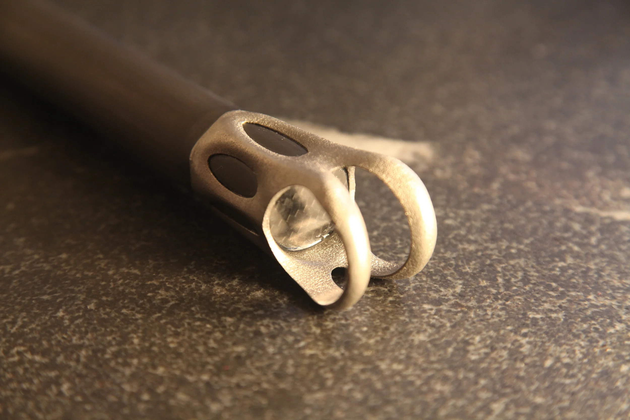
The part in question is the head of a seatpost assembly for high end road bikes. The part itself is small - about 70mm tall and with a 35mm square footprint. As built, it's just 32g of titanium 6/4. Add in a piece of carbon fiber tubing (88g for a 300mm length) and some rail clamp hardware (50g), and the entire seatpost assembly should be in the 175g range - on par with the lightest seatposts on the market today.

As a product manager who's ultimately optimizing for commercial viability, I had three questions going into this process:

  1. How do the costs of the different manufacturing process chains compare? 
  2. How do the resulting parts compare functionally, i.e. in destructive testing?
  3. Functionality being equal, how do the aesthetics (and hence desirability) of the parts compare?

I'll write more about the second point later; in this post, my primary aim is to introduce MMP and compare the different process chains from a financial and operational standpoint.

Basics of surface texture

As confirmed by a 1990 NIST report titled Surface Finish Metrology Tutorial, "there is a bewildering variety of techniques for measuring surface finish." Moreover, most measurement methods focus only on the primary texture - the roughness itself - and incorporate some method of controlling for waviness and form. From the same report:

The measured profile is a combination of the primary and secondary texture. These distinctions are useful but they are arbitrary in nature and hence, vary with manufacturing process. It has been shown, but not conclusively proven that the functional effects of form error, waviness and roughness are different. Therefore, it has become an accepted practice to exclude waviness before roughness is numerically assessed.

Surface finish is usually measured using the stylus technique:

The most common technique for measuring surface profile makes use of a sharp diamond stylus. The stylus is drawn over an irregular surface at a constant speed to obtain the variation in surface height with horizontal displacement.

The most common surface texture metric is Ra. (For a good, quick, technical description of the varieties of surface texture metrics, see this PDF from Accretech.) Ra measures the average deviation of the profile from the mean line (the related Rq also measures deviation from the mean line, but using a root mean square method), and is used across a variety of industries and manufacturing methods. But it's incapable of describing a number of important aspects of a part. For instance, it's critical (for both aestetic and functional reasons) that my parts have Rsk (skewness) values close to zero - meaning that their surfaces are free from flaws like pits and warts. In other words, I'd take a consistent, brushed surface over one that's highly polished but has a few deep cuts/pits.

I should note, of course, that surface finish is a result of the total manufacturing process chain. If the near net shape part (straight out of the EBM machine) is rough and pitted, then it'll be difficult to ever make it acceptable - and the methods required to do so will vary widely. 

MicroTek and MMP

MicroTek is just one in an international network of companies that perform MMP, which grew out of a Swiss company called BESTinCLASS Industries. The MMP process is closely guarded; neither MicroTek nor BiC disclose enough about the process to really understand how it works. From MicroTek's website:

MMP Technology is a mechanical-physical-catalyst surface treatment applied to items placed inside a processing tank.  MMP technology is truly different from traditional polishing processes because of the way it interacts with the surface being treated.
MMP Technology uses a mechanical cutting process at a very small scale (not an acid attack or any other process that could alter the part's metallurgical properties), meaning it can distinguish between micro-roughness and small features. The process actually maps the surface as a collection of frequencies of roughness, removing first the highest frequencies, then removing progressively lower frequencies.
Unlike other polishing processes, MMP Technology can stop at any point along the way, so now for the first time it is possible to selectively remove only the ranges of roughness that you don't want on the surface, giving you the option of leaving behind lower frequencies of roughness that could be beneficial to the function of the part.

To hear Tim and JT Stone tell it, MicroTek essentially does a Fourier transform on the topography of the part. They analyze the surface finish as the combination of many low and high frequency functions, and begin the MMP process by characterizing those different functions and identifying which ones to remove. Then, by selecting "an appropriate regimen of MMP Technology from the several hundred treatments available," they selectively remove the undesirable aspects of the surface finish - while still preserving the underlying form of the part.

This is worth highlighting: traditionally, polishing is a process whereby a part is eaten away by abrasive media. With each successive step, progressively smaller scratches are made in the part's surface. You're constantly cutting down the peaks of the part, and as a result the form gets smaller and smaller over time. With MMP, you have the flexibility to remove fine frequencies while keeping longer ones - maintaining the original intended shape.

The parts

Addaero printed three identical parts for me. I sent two to MicroTek. They processed one for fatigue resistance, and the other they "made BLING."

(Note that you can click on the photos above to see a larger version.)

MicroTek sent detailed inspection reports with the parts, and the picture they paint is fascinating. MMP reduced both Ra and Rq drastically, and Rt dropped significantly as well. Rsk is a bit of a different story, however: in one of the measurement locations ("Side of leg"), it dropped well into the negative range. You'll recall that the absolute value of skewness is really the issue here; a negative number (indicating pitting) is just as bad as a positive (indicating warts/spikes) one.

I've put the raw data in a Google Sheet, here; the full inspection reports are here and here. The charts below show most of the relevant information, broken down by the area of the part being tested. A helpful description of the part's areas ("V-neck face," etc) is here.

Ra - Roughness average

All values in μm

Rq - Roughness, root mean square

All values in μm

Rsk - Roughness skewness

All values in μm

Rt - Roughness total

All values in μm

MicroTek also sent a series of photos taken with a Hirox digital microscope at a variety of magnifications:

If it's not clear from all of the photos and charts above, the improvement on the parts due to MMP is really remarkable. The as-printed part is really rough - on average, it's about as rough (Ra/Rq) as 120 grit sandpaper (see this for a good analysis of sandpaper surface texture). MicroTek was able to eliminate the vast majority of the total and arithmetic mean roughness; both parts they processed feel very much like finished products.

The pitting, however, is a problem. To be clear, it's not a result of the MMP process; all they did was expose flaws that were already in the part. Many of these could probably be eliminated on future batches. First, printing the parts on a newer Arcam system (like the Q20) might improve the as-printed texture significantly. And second, MicroTek can investigate more complex treatments that allow for the offending frequencies to be eliminated more thoroughly. I'll be exploring these (and other) options in the coming months.

Assembly

Before putting the seatposts together, a little bit of prep was necessary. The inner diameter of both the seatpost and saddle clamp cylinders were slightly undersized, and there were warts (remnants of support structures) left on the undersides of the shoulder straps. I had intentionally left these untouched when I sent the parts to MicroTek, as I wanted to see how little post processing I could get away with. The MMP process took them down slightly, but not nearly enough to put the parts into service.

Fixing that was pretty straightforward - just a few minutes each with a file. In future iterations, I'm hoping that by making some light design modifications - and by dialing in the EBM build parameters - will minimize this work. If not, then I'll probably add CNC machining into my process chain (after printing and before finishing).

With the inner diameters trued up, the parts could be dry fitted to the carbon fiber tubing I'm using as a seatpost:

I'll be gluing the assemblies together with 3M DP420 this week, and then I'll send them out for testing. These parts will be put to the same ISO standard that my seatmast topper passed last summer, and I'm particularly curious to know whether the different levels of post processing has any effect on their strength. In high fatigue cycle applications (this paper defines "high fatigue cycle" as N>100,000, which is exactly what my parts will be tested to), improvements in surface finish (lower Ra) have been shown to increase fatigue life. If some form of surface finishing (MMP or otherwise) means that I can print a lighter AND stronger part, that'll definitely help justify the expense.

Cost

With my current design and a batch size of 275 (a full batch in an Arcam Q20) my as printed cost will be under $100. MMP will cost an additional $40-75 (depending on finish level), though those numbers were based on smaller quantities. I'd hope that the rollup cost to me is under $150.

In addition to these parts, a full seatpost requires about $25 worth of carbon fiber, a few dollars worth of glue, and (I suspect) under ten minutes of assembly time. They'll also require saddle rail hardware, which I'm budgeting an additional $25 for, and some packaging - under $10. All told, my cost of goods sold would be about $215.

That's a fancy seatpost, but it's not completely unreasonable. My goal, at the moment, is to get that price down to $150.

More updates soon :)


Thanks to Addaero and MicroTek for their ongoing help with this project.

Coming soon

Added on by Spencer Wright.

Today I *finally* found time to photograph the parts that I got back from MicroTek a few weeks ago:

As you can probably see, the part on the left is unfinished. In the middle is an intermediate finish (~25µ" Ra), and on the right is a fine finish (~1.5µ" Ra). All three of these parts were printed on Addaero's Arcam A2X; their raw finish is about 600µ" Ra. 

Incidentally, I'll note that photographing the surface finishes on these parts has been remarkably challenging. I probably need a strobe or something, but hey - it's a labor of love.

I'll be writing up the results in the next few weeks. Stay tuned!

My writing in Metal Additive Manufacturing Magazine

Added on by Spencer Wright.

I'm extremely proud to say that my writing is featured in the current issue of Metal Additive Manufacturing Magazine. The article summarizes much of my work over the past two years, and includes many of my thoughts about how the industry can be better in the future. You can read the full article here.

Thanks so much to Nick Williams and the rest of the Metal AM for asking me to contribute!

DMLS vs EBM titanium parts

Added on by Spencer Wright.

Note: Below, I use the term "DMLS" to refer to laser metal powder bed fusion. Some will have issues with this usage; I encourage readers to ignore the (possibly trademarked) terms themselves and focus on the information contained within them.
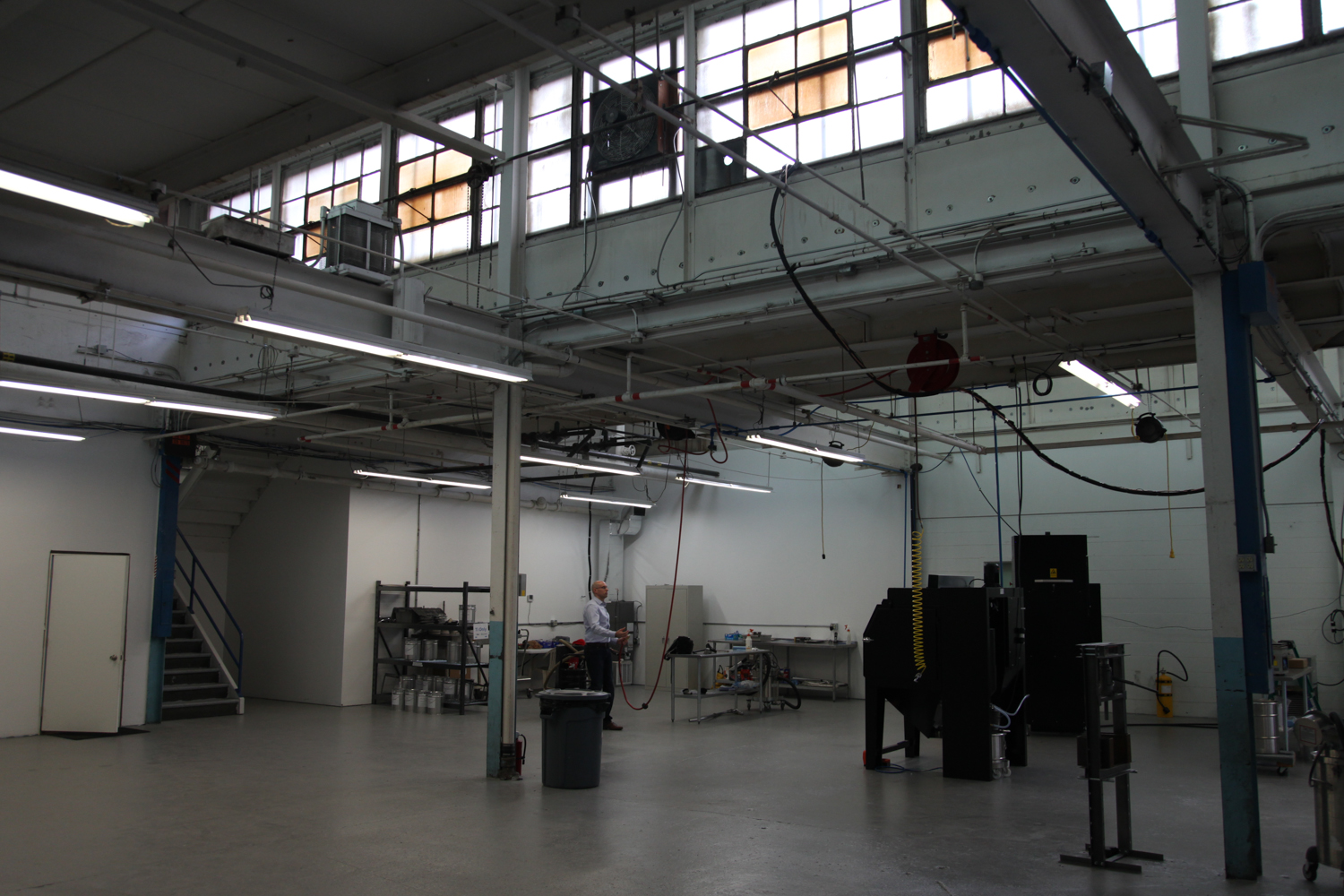
Over the past few months I've spent a lot of time trying to determine whether DMLS or EBM would be a more suitable technology for the titanium bike parts I'm working on. Early on (in my collaborations with DRT and Layerwise) I focused on DMLS, and more recently I've worked with Addaero on EBM. These two technologies are in many ways complementary, and in truth I expect to work with both of them - but their design constraints and total manufacturing process chain are a bit different, and I wanted to spend some time understanding how that will affect the cost and quality of the parts I'm working on.
In the video below, I show some of the basic differences in surface quality and support structures. Of course there are many other factors that are worth exploration, starting with minimum feature size and built-in stress, probably; I'll get to those in future updates.

This video gives an overview of the differences between DMLS and EBM titanium parts. I show basic surface finish characteristics, support structures, and support removal.

Incidentally, I'm *really* interested to see the differences between DMLS and EBM in printing the lattice structures I've been working on. More soon :)

New EBM prints from Addaero

Added on by Spencer Wright.

Yesterday I went up to visit Rich, Dave, and Cesar at Addaero, and came home with a few new EBM prints. These are an iteration on the parts they printed me a few months back, and should be easier to post-process (and are lighter to boot :). 

I'm working on getting a better understanding of the differences in manufacturing process chain in DMLS and EBM (a life-cycle assessment of sorts), and one big difference ultimately will be surface finish treatments. As a result, I'll be sending these parts off to a few special places to get some very special surface treatments applied to them - and then will send them to EFBE for testing. It's likely that different treatments will result in different mechanical properties, and they'll definitely result in different cost structures as well. Stay tuned for updates :)

Improved laser build

Added on by Spencer Wright.

Learning new software is fun. This is me after a few hours playing with Materialise Magics 19 and SG+.

I've made a few modifications to the standard build:

  • Changed the surface selection angle to 50°. This build is set up for laser metal powder bed fusion (aka DMLS), which will print angles a bit below that, and it's very possible that 50° isn't optimal.
  • Changed the upper supports so that they're angled. In my last post you'll notice that if these are vertical, they'll rest on the bottom face of the cylinder. While that may be fine structurally, it means that I'd have that much more to clean up, and I think I'd rather have the supports go all the way down to the build plate instead. It's *possible* that this will reduce the amount of post processing necessary on the part - you'd need to run multiple builds with different configurations to be sure.

It's worth noting that this part is too far off the build plate right now - I'm still trying to get used to Magics' UI, and figured it didn't matter for now. I should probably also orient the part at a slight angle from vertical (see my recent post, here, for more details on this); again, I'll play with that a bit more later.

Oh, and I probably want to add additional reinforcements to the short ID, to make sure that it prints round. I'm looking at a few methods of doing this, most of which would require some work back in solid CAD (Inventor), or *possibly* some volumetric mesh generation software (like nTopology). 

I'm definitely still getting used to Magics' philosophical perspective on the additive process chain, too. I have some thoughts on what this is, but will play around more before I share them :)

Stay tuned.

Some quick modeling

Added on by Spencer Wright.

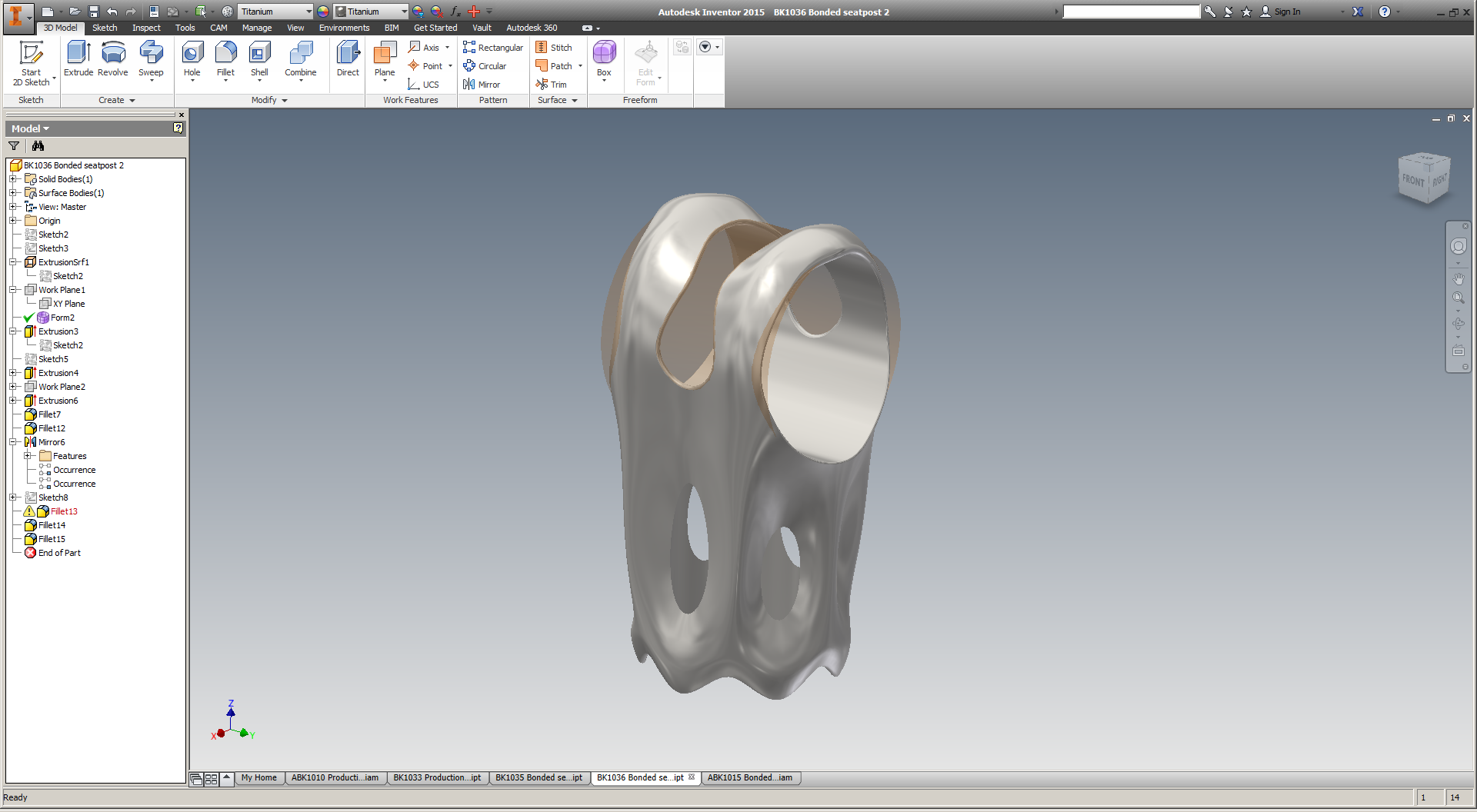
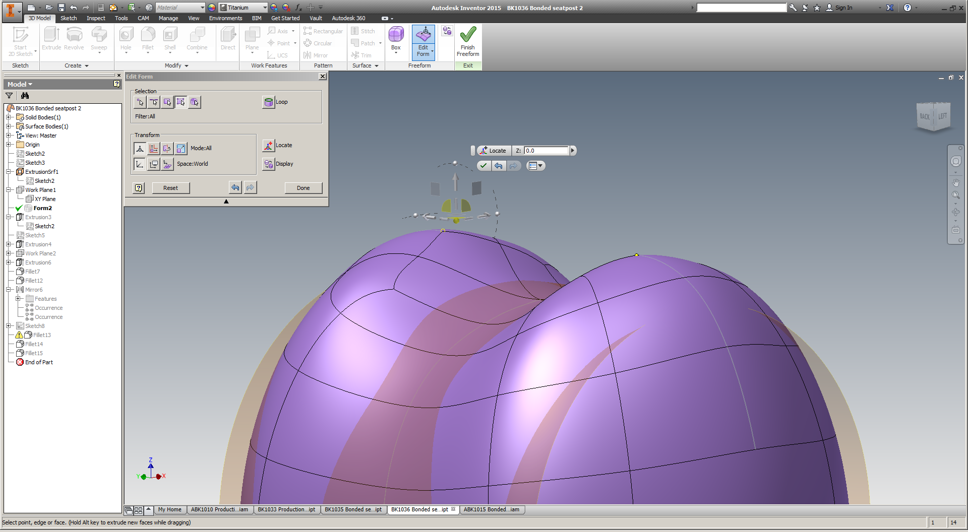
It's been a little while since I've played with this design, and I enjoyed getting back in to it. To be honest I'd like to spend a few days working on the model (I'd probably tear it down completely and start from scratch) but for now this is looking pretty nice.

Incidentally, T-splines continue to be *really* weird - and super cool. I really wish I had a more powerful computer; I suspect that would improve the experience significantly.

Planning for post processing

Added on by Spencer Wright.

The other day I got an email update from Rob Oliver, a machinist in Brooklyn who's helping me post process the EBM printed titanium parts that I got from Addaero recently. There's still a bunch of work to be done, but I wanted to write a bit about how we're thinking of the manufacturing plan - and the constraints that we're facing in the process.

While electron beam melting tends to produce much lower internal stress than laser powder bed fusion does, it's still a decidedly near net shape process. In further iterations I hope to get the as-printed part much closer to the final dimensions, but at this stage the parts I have deviate significantly from the intended tolerances. Specifically, most outer dimensions seem to have grown, most inner dimensions seem to have shrunk, and there are a number of locations where support structures have left unacceptable surface finishes.

My main focus right now is getting both inner diameters to within .006" of their designed size. It's difficult to get a reliable measurement of where they are now (due mostly to surface finish, and the presence of leftover support material), but they both appear to be about .040" undersized. In addition, I suspect that the shorter cylinder is slighly ovalized - though not to the extent that it'll be an issue in the end.

Although there are other conceivable options, the most obvious way to get the IDs within tolerance is milling. By using either a CNC toolpath on an end mill, or a boring bar on a conventional mill, it should be very easy to get well within .006" of nominal dimensions on both areas of the part. However, the issue of fixturing is nontrivial. I designed this part with T-splines, and its outer surfaces aren't orthogonal at all. As a result, we'll need custom tooling to hold the parts in a milling vise.

As an aside: Anyone who says that additive manufacturing eliminates the need for custom tooling has no idea what they're talking about. 

In order to securely fixture this part, Rob is machining its negative into a set of aluminum blocks, which can then be clamped securely into a milling machine vise. This technique (which I'll refer to here as "soft jaws," although technically what we're making is more of a coped fixturing block) is used extensively in subtractive manufacturing to hold irregularly shaped parts. 

The process of making soft jaws is relatively straightforward, but designing them for this part is somewhat complicated by the dimensional variation that EBM produces. Put simply, feature sizes in EBM parts tend to deviate from the design in the X and Y axes, but stay relatively true to size in the Z. That's because the Z axis is at least partly controlled by the Z stage drive system; the powder bed is lowered a predictable amount with each new layer, keeping features in the Z close to their designed dimensions. But in the X and Y, deviations in feature size are partly driven by the electron beam diameter, and partly driven by the distance that the feature is from the center of the build platform. 

As a result, my part has grown anisotropically, and Rob will need (to some extent or another; soft jaws tend to be somewhat forgiving) to compensate for the as-printed dimensions differently in the XY plane than he does in the Z.

In the end, though, the most practical way of determining the final dimensions of the soft jaws is to make a set, test them on the as-printed part, and iterate as necessary. It's conceivable that the first try will work, and it's also possible that if we make the negative a bit too big in all directions, we could use a piece of soft material (for instance, blue tape) to take up the gap.

It's also worth noting that there's an alternative path that I decided *not* to take. A common way to make parts - both with additive manufacturing and conventional - is to design fixturing features into an intermediate stage of the part. These can then be used to hold the part while secondary operations are performed; they can then be removed in a subsequent step. I considered this option, but find it undesirable for the simple reason that it would likely result in more post processing steps. Worse yet, it would probably require the surface of the part to be blended where the fixturing element had been removed, which would be either labor intensive, or unattractive, or both.

Regardless, we should have the first iteration of our soft jaws machined shortly. Expect updates!

First EBM prints

Added on by Spencer Wright.

A few weeks ago I visited Addaero Manufacturing, one of the very few EBM (electron beam melting) service providers in the US. After my recent trials (and successes) with laser powder bed fusion, I wanted to try building parts with EBM. EBM is used extensively by aerospace and medical OEMs, but its penetration into the job shop world is way behind laser. Addaero, whose founders (Rich Merlino and Dave Hill) both worked at Pratt & Whitney before striking out on their own, is located just a few hours from New York City, and they were gracious enough to build two parts for me to evaluate the process.

I'll be writing up a longer post on the unique design considerations that EBM poses, but for now I wanted to share the pictures I took while there:

At this point, the parts Addaero made for me still need post processing before they can be assembled and tested. I'll be working on that over the coming weeks, and will update soon on my progress.

T-spline redesign

Added on by Spencer Wright.

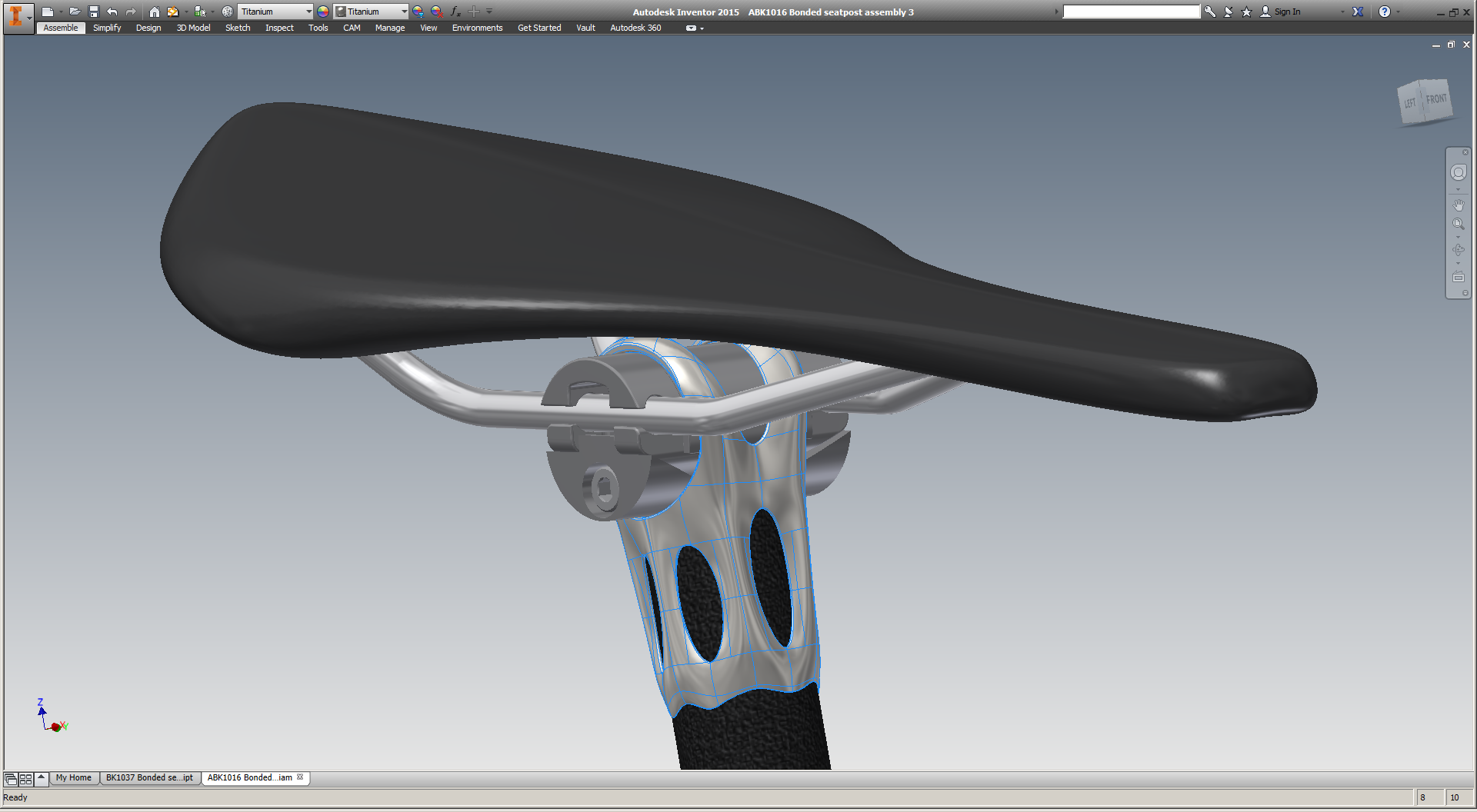
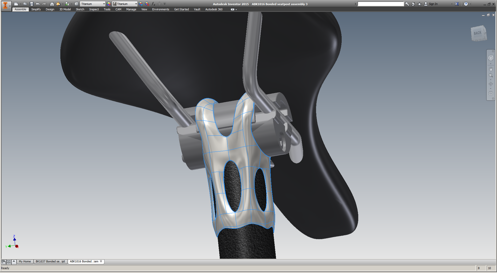
As my seatmast topper has been moving towards destructive testing, I've been playing with a new seatpost design. This part would probably be EBM'd, and then bonded (with 3M DP420 or similar epoxy) to 27.2mm carbon fiber seatpost stock. I suspect that this design will be a bit more economical, and would work on a wider range of bicycles - including my own.

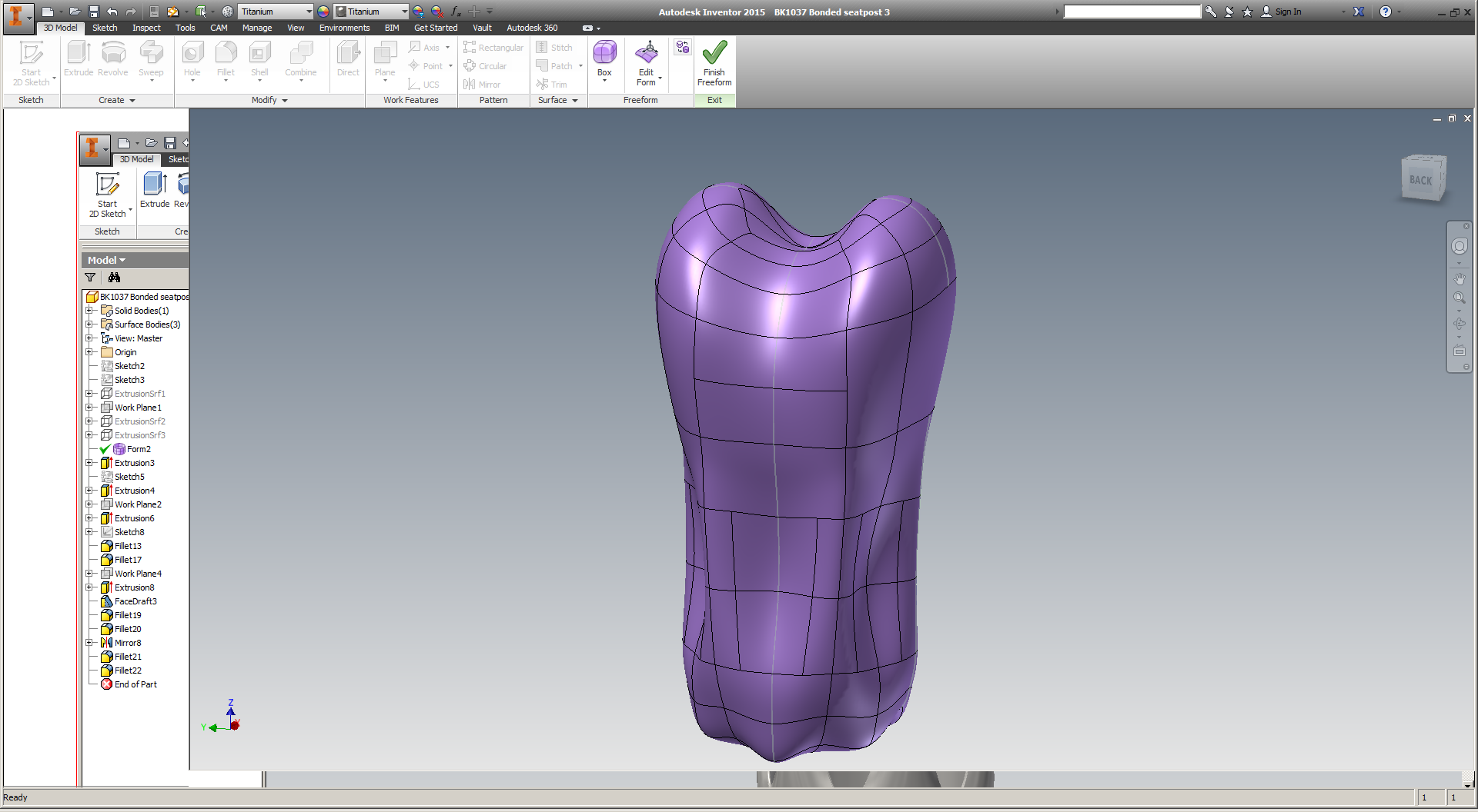
I've been pursuing the redesign in a few ways. First, I've been working with a few NYC folks to develop designs that incorporate either topology optimization, or lattice structures, or possibly both (more on this soon). Second, I got a trial license of SolidThinking Inspire, and have been using that to reduce mass within a design space that I set up in Inventor. And third, I took a crack at designing the part from scratch with T-splines in Inventor, which I *really* enjoy.

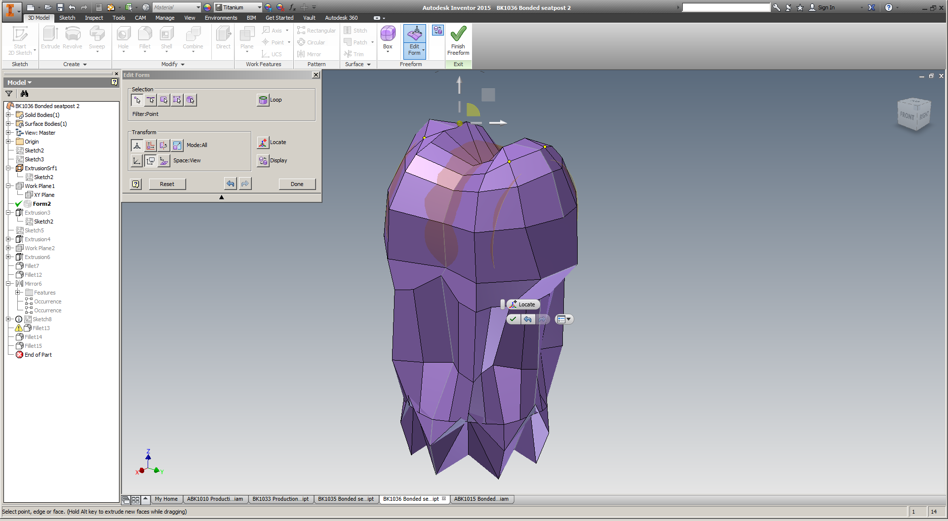
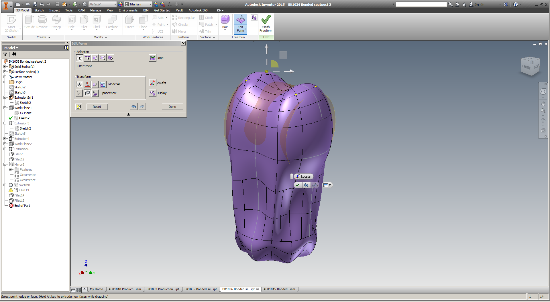
T-splines are a totally different way of approaching design, and they allow you to manually create organic looking structures. Once I've created the organic shape, I apply a bunch of features to it in Inventor's solid environment - allowing me to blend precise mechanical aspects within an otherwise fluid shape.

Ultimately, I'm optimistic that topology optimization & lattices will offer a less labor intensive workflow. T-splines are *awesome,* but editing them is a bit of an art, and I'd like to be able to redesign the part quickly to accommodate different saddle offsets, strength limits, seatpost diameters, etc.

Expect more progress soon :)