Note: Special thanks to Bradley Rothenberg (of nTopology) and Ryan Schmidt (of MeshMixer/Autodesk) for their continued help on this workflow. Also, both of them make awesome (and very weird ;) software that you should check out.
A scenario: You've got a part that you want to manufacture with metal powder bed fusion. You've got a few mechanical features that you know you need (to mate up with other parts in an assembly) and a general sense of the design space that's available for the part you're designing. You know the mechanical properties you need (via an ISO test that the part needs to pass) and you've got a target mass (which is basically "less than the competition"), and a target cost (which is basically "similar to the competition, taking into account a ~35% margin for me").
I've spent a lot of the past week going back and forth between Inventor, MeshMixer, and nTopology Element, trying to make a 3D lattice structures that are both mechanically effective and easy to manufacture. My workflow has been decidedly emergent, and it's also been counterintuitive at times; I've often found myself working backwards (away from my final design intent) in order to create the conditions where I can make progress down the line. My end goal is to design a bike stem that's sub 125g and which has minimal post-processing costs and requires minimal support structures (I'll deal with the actual dollar cost later, as it'll depend on a bunch of factors that aren't under my direct control).
I've got 27.7 cubic centimeters of titanium to play with. Where do I put it?
I began in Inventor. Setting up a design space is, counterintuitively, kind of a hard thing to do. Very few parts that I've designed have hard and fast design space boundaries; most of them could always be a little bigger, or a little smaller, and the rest of the assembly would stretch or squish to accommodate it. Nevertheless, I need to start somewhere, so I created a T-spline form that was close to what I thought I'd want:
I export it as an STL at low resolution (where we're going, resolution doesn't matter :) and bring it into MeshMixer:
From here, things start to get complicated. The way I see it, this part essentially has three components:
- The mechanical features. This includes the two clamp cylinders (one, the handlebar clamp, is 31.8mm in diameter and split; the other, the steer tube, is 28.6mm and slit along the back side) and the four bolt holes (all M5, and all with one counterbored part and one threaded part) that do the clamping.
- The design space's exterior surface. In general, the stiffness of the part will be determined by how much volume it takes up, and I should generally make the part as stiff as possible. Therefore the exterior surface of the part is going to be made up of a big non-Euclidian 2D lattice.
- The volume of space between the mechanical features and the exterior surface. I'll want some bracing here to tie the whole part together and transfer loads from the mechanical parts over to the exterior lattice.
For this design, I'm using lattice structures throughout the part. I won't design any skins (I'm generally anti-skin, unless you've got fluid separation requirements in your design), instead opting to let the lattices vary in density from zero (in the middle of the part) to 100% (in areas like the threaded and counterbored bolt holes).
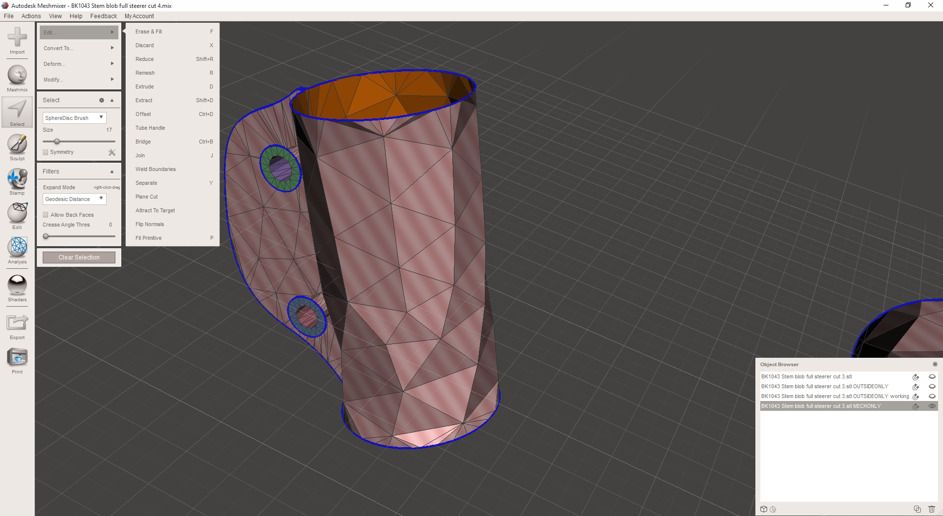
Because the different surface regions of the part (the mechanical features and the exterior surface) will have different mechanical requirements, I begin by duplicating my lattice in MeshMixer and isolating each of them in its own object:
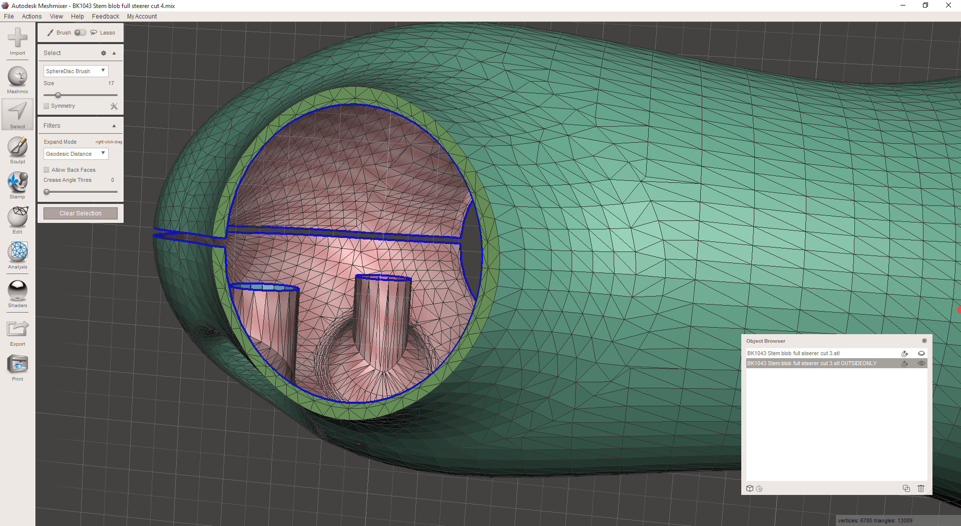
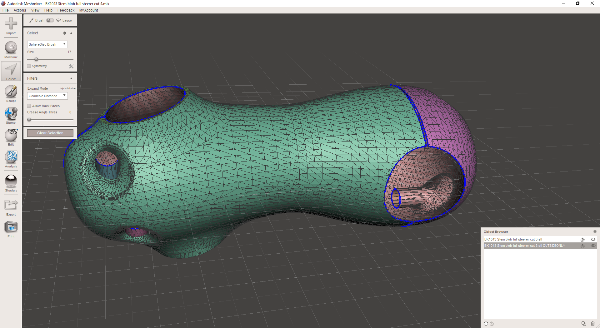
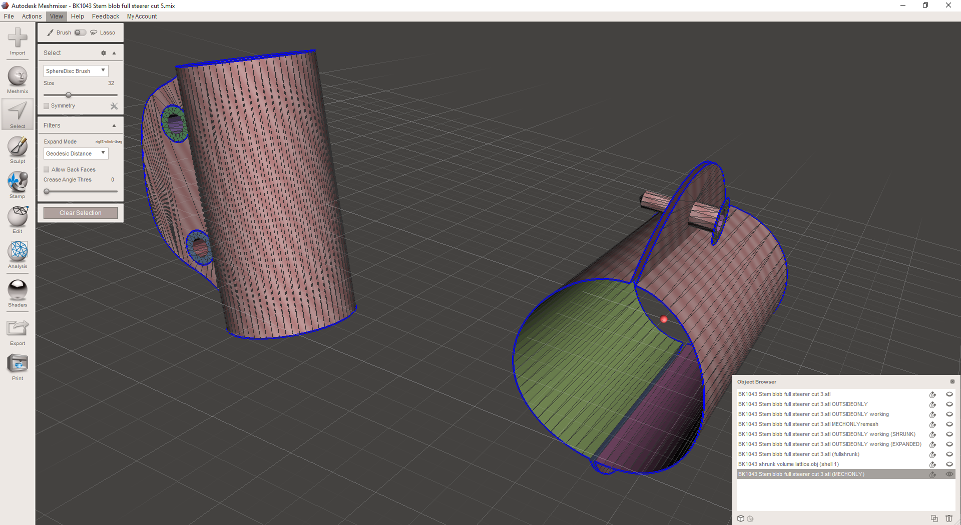
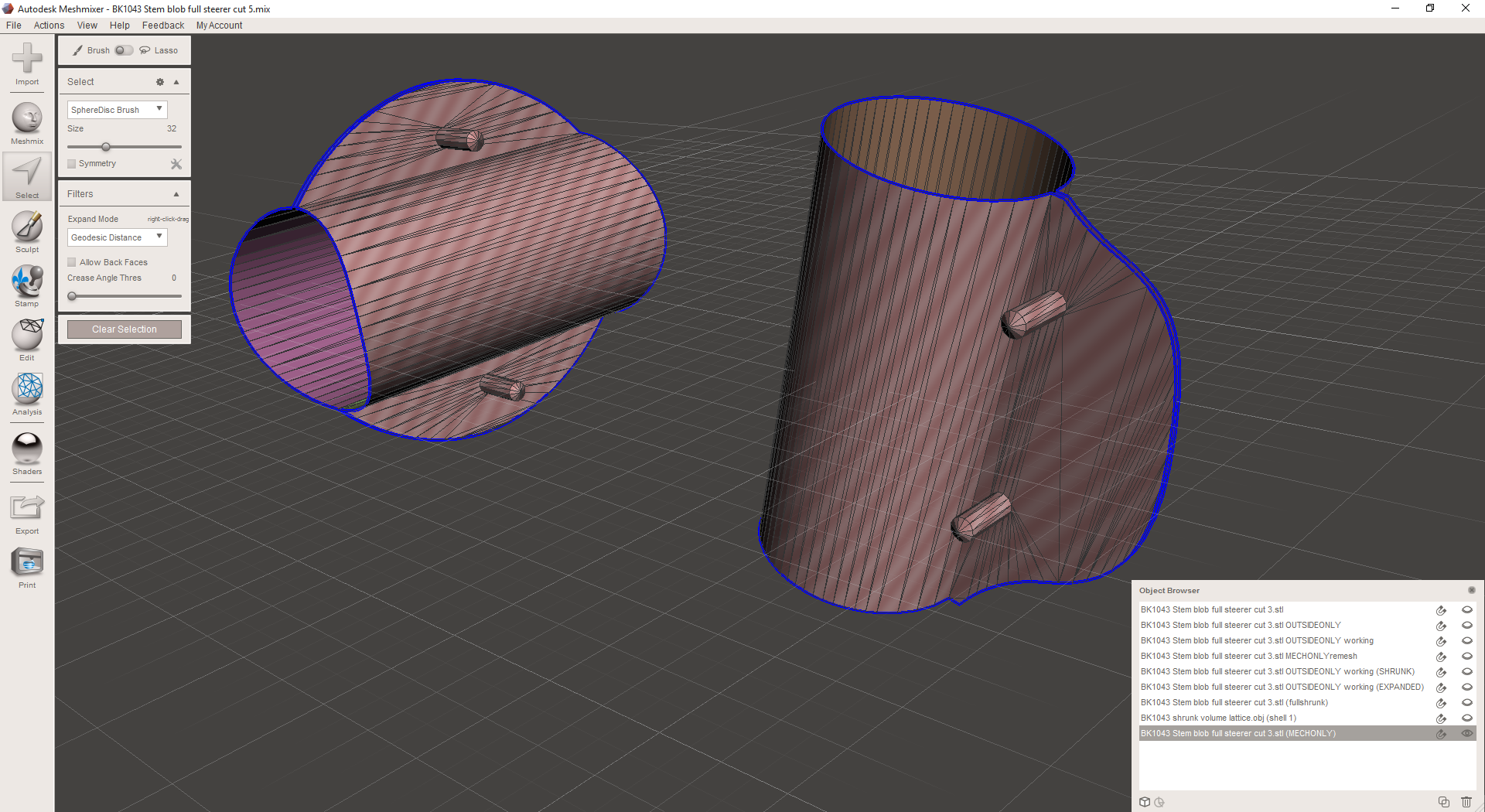
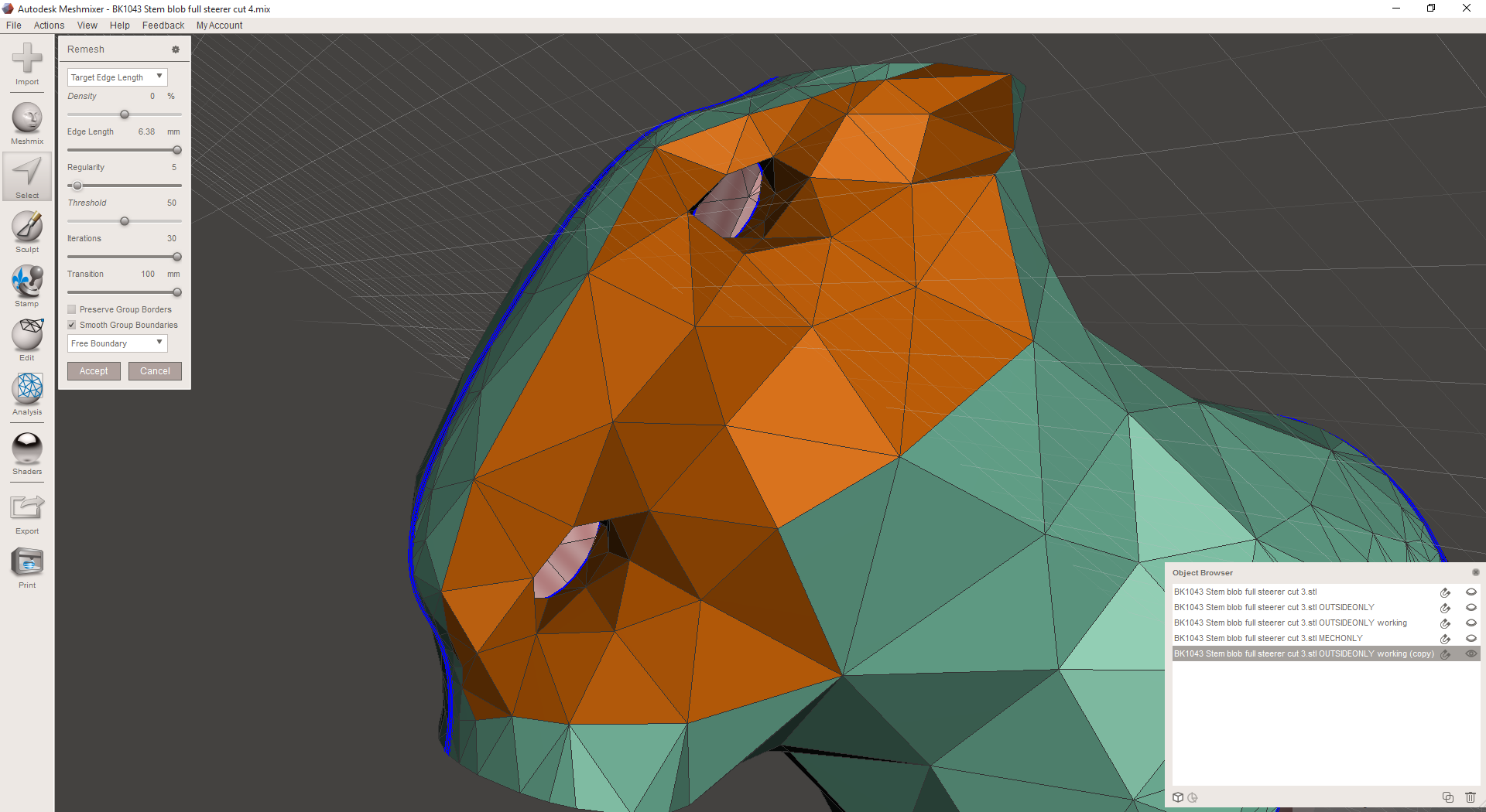
I then go through each region and remesh it in MeshMixer. A few notes here:
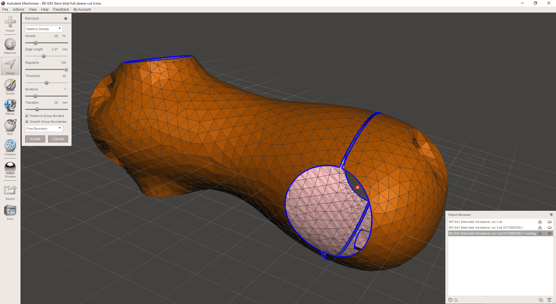
- I generally begin by remeshing the entire object at a medium-high resolution, just to get rid of the dense lattices that Inventor creates at edges and small fillets.
- I then choose the area that I want to be at the highest resolution (which is almost always lower than the one I chose in the first step) and remesh it. On the part's exterior, that was the bolt counterbores.
- Then I work my way down to the lowest resolution areas. On the part's exterior, I targeted edges in the 15mm range, but I play around with the remesh settings a *lot* until I get something I like.
- Then I'll go back and find areas that are still a bit high-res and remesh them again until they look good. There's a bit of back and forth here, and I haven't really figured out a one-size-fits-all workflow yet.
I DON'T worry about geometric accuracy much during this process; I assume that I'll need to clean up the geometry at the end (after I've generated the full lattice structure - more on this in a future post) anyway.
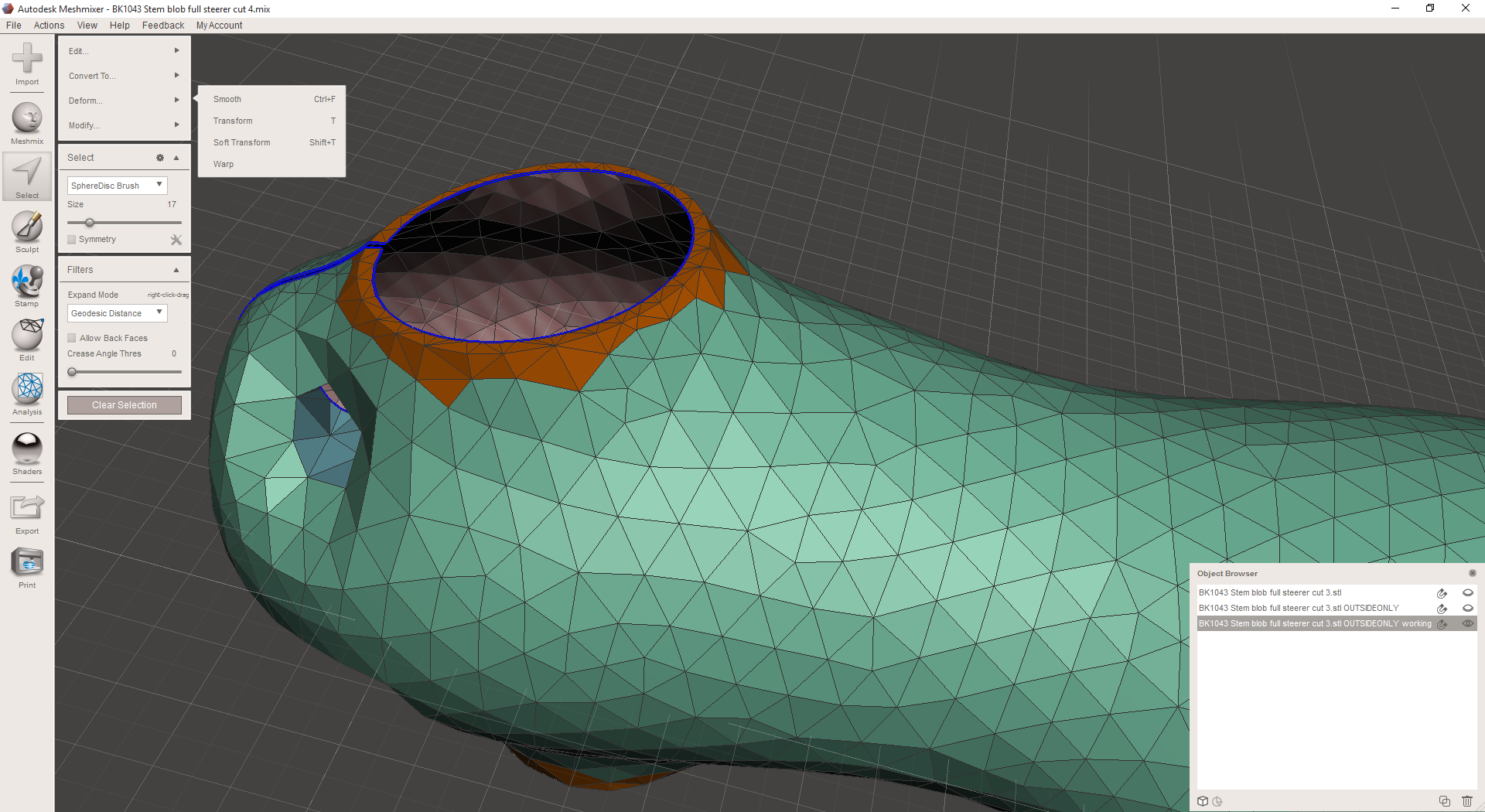
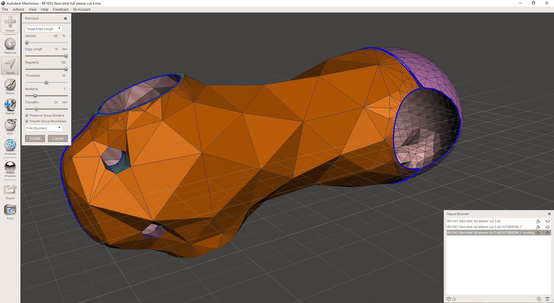
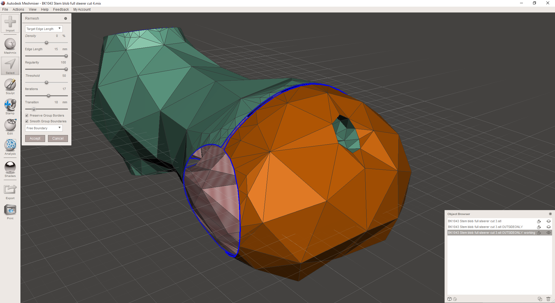
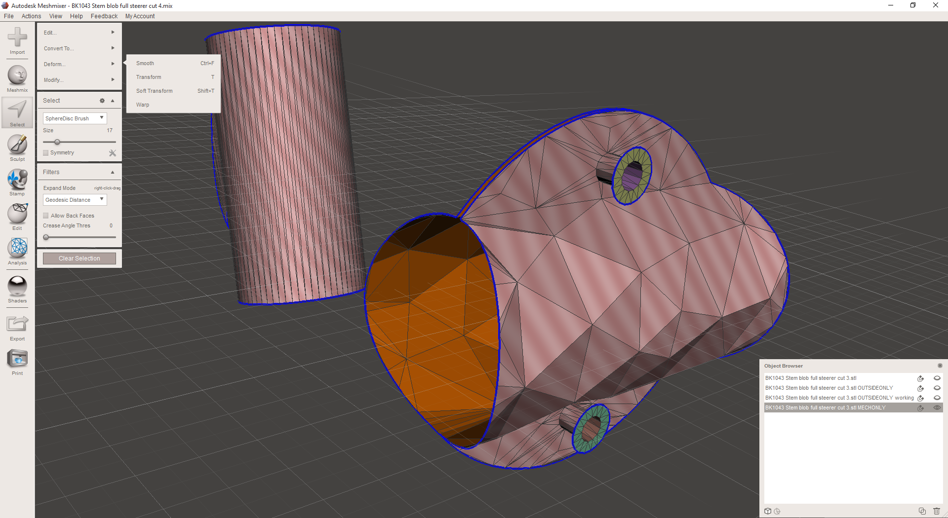
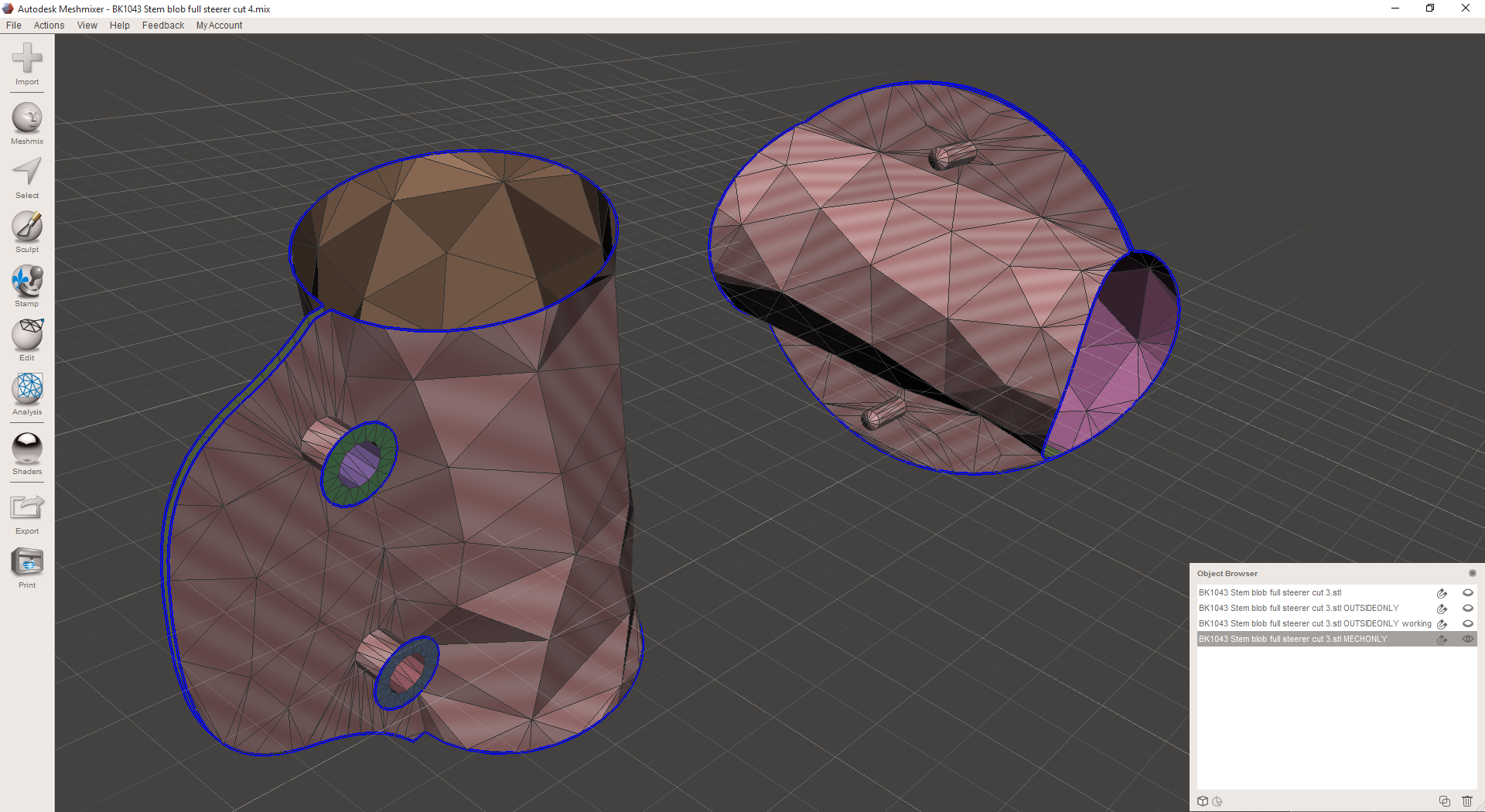
Then I export the lattices as OBJs, bring them into nTopology Element, and see what they look like:
At this point, I decided that I really wanted to stretch the entire exterior lattice out so that more of the beams would be horizontal. The part will probably be built on its end, so these will be easier to build as a result. So I go back into MeshMixer, transform the part down (it happens to be the Z axis here) by 50%, and remesh the outer skin. Then I transform it back up to 100%, stretching everything out.
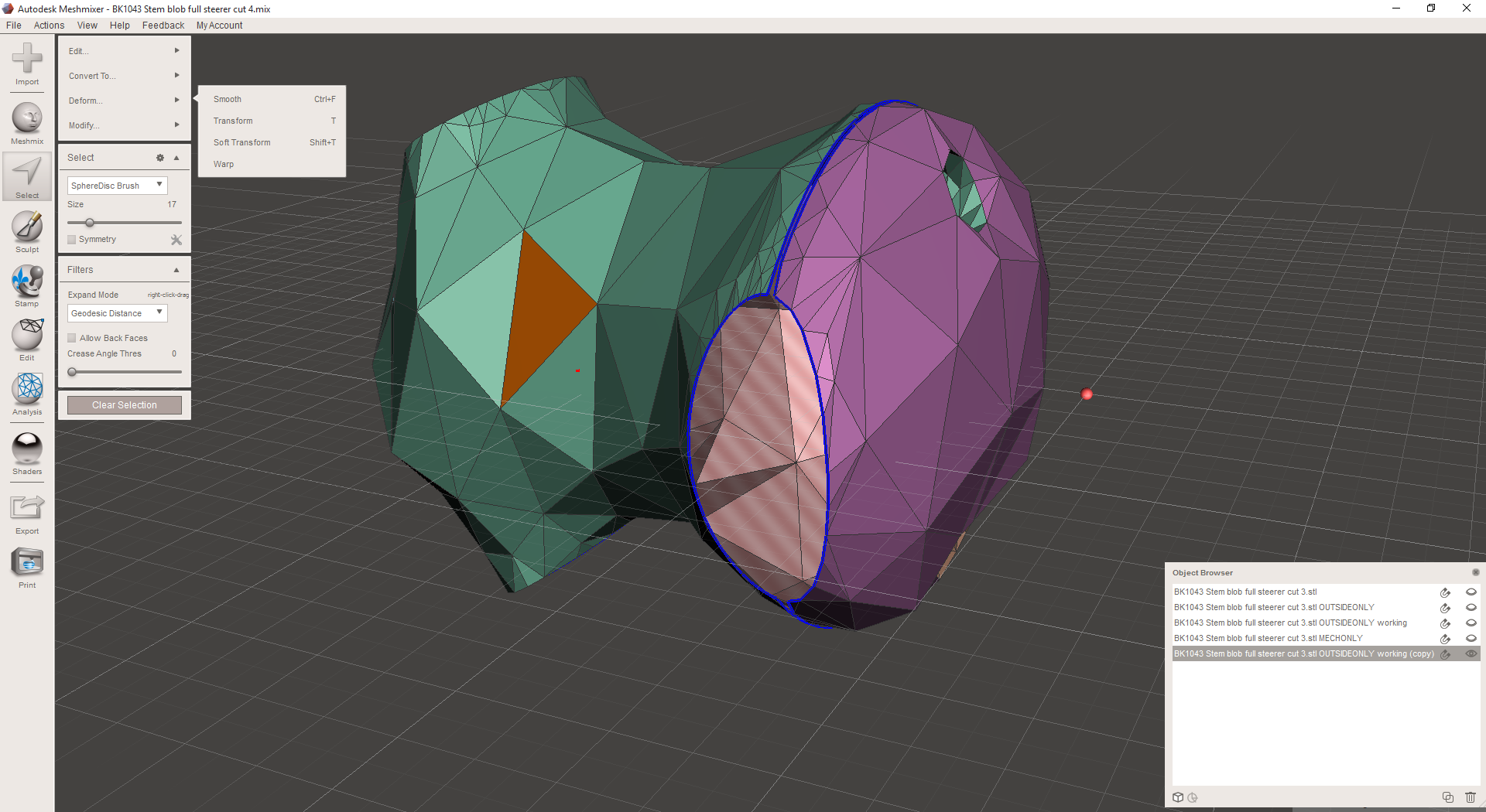
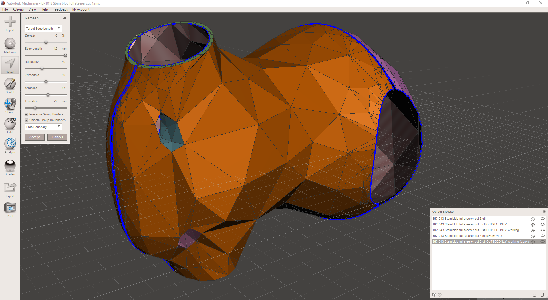
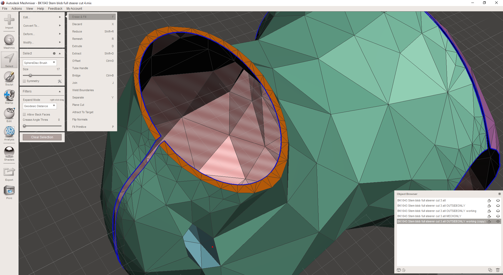
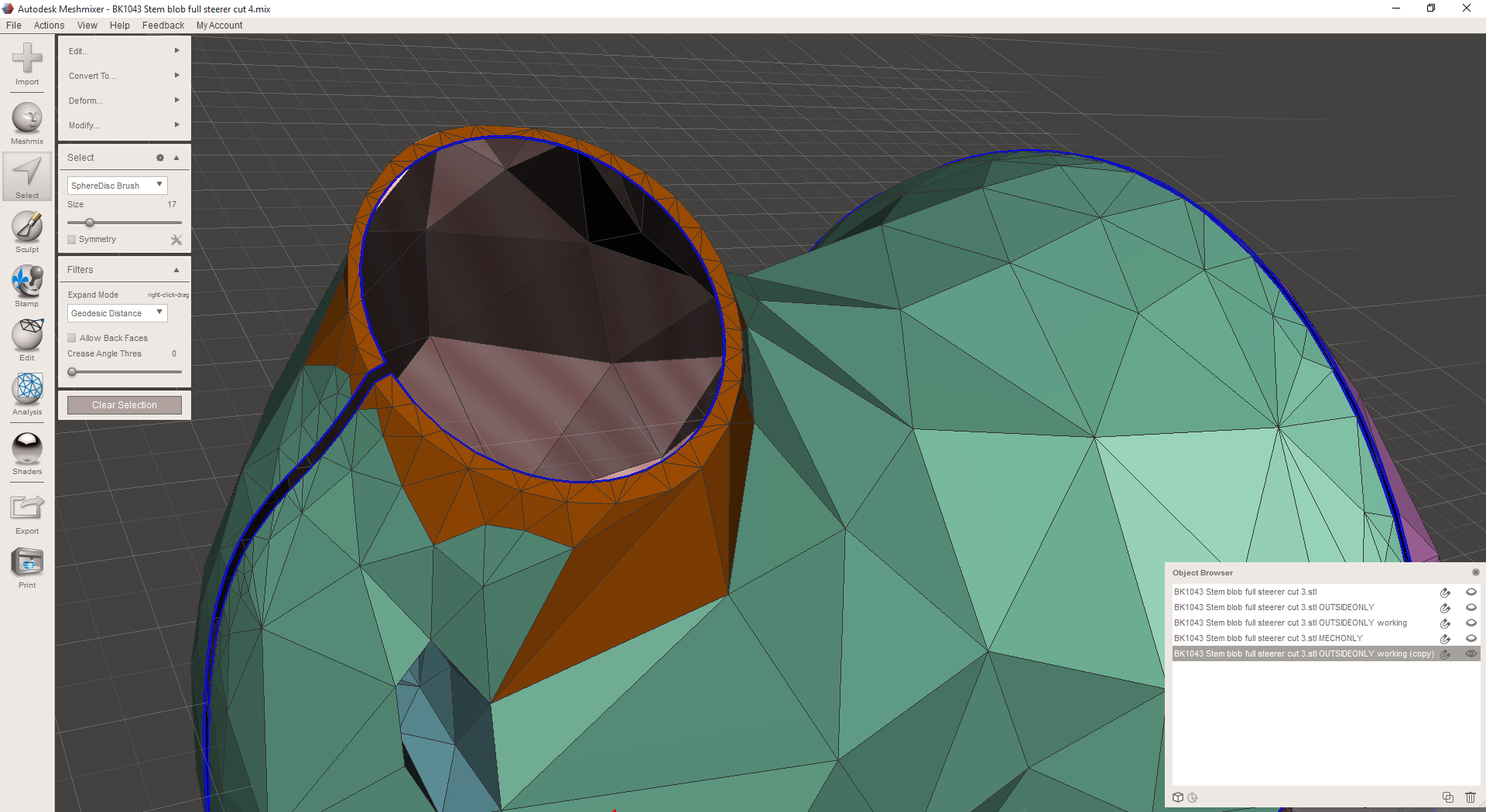
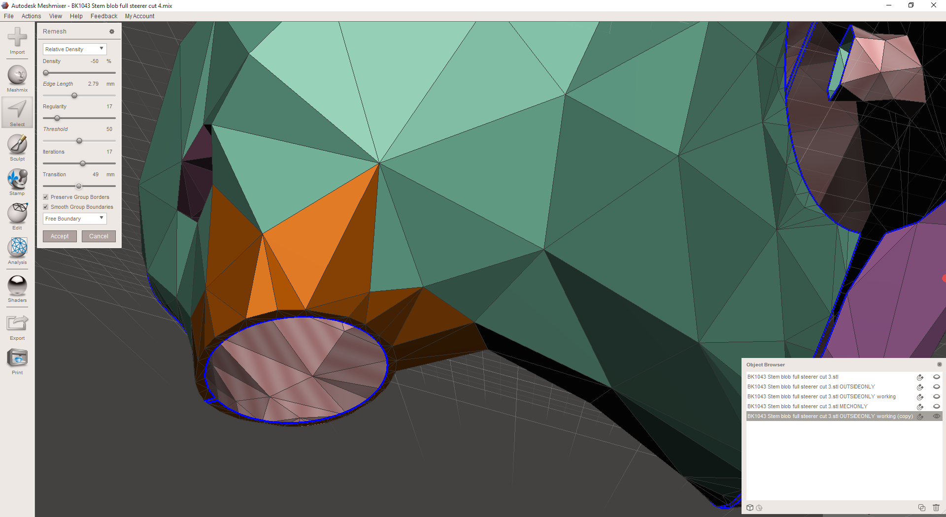
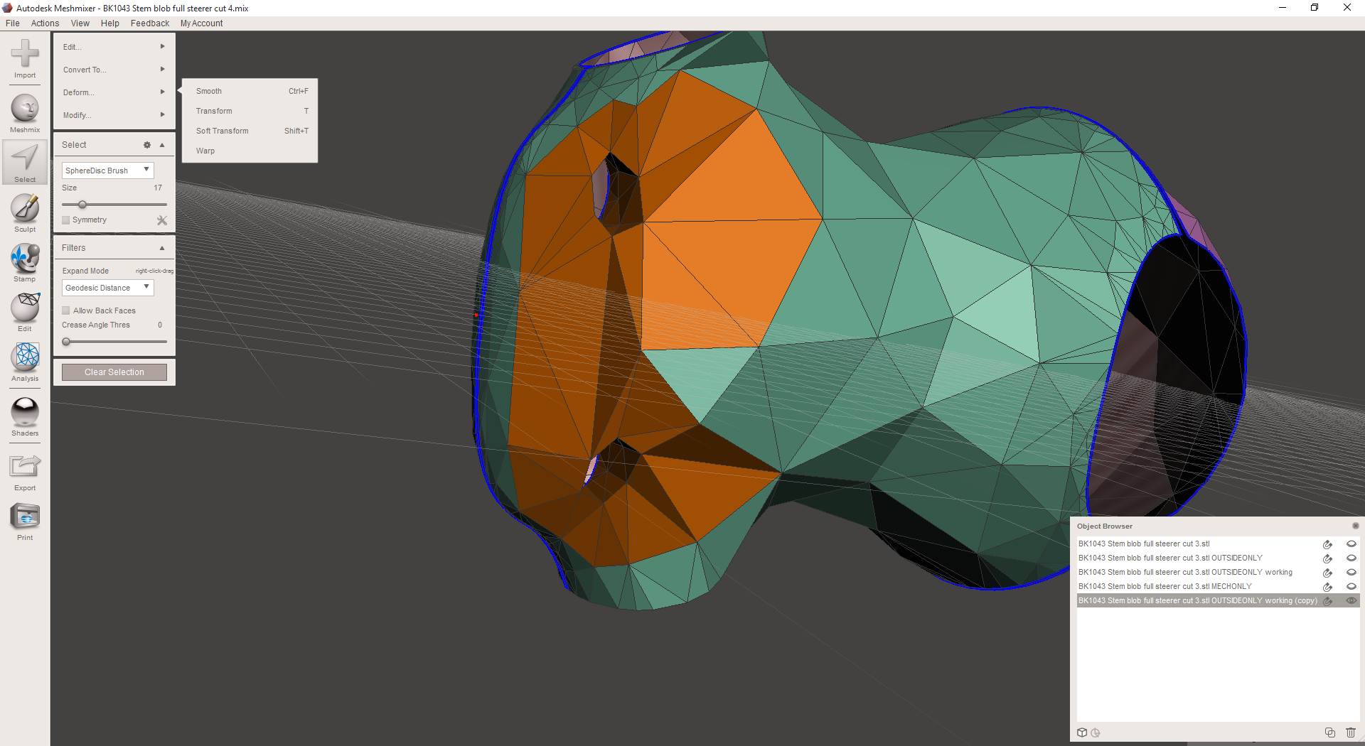
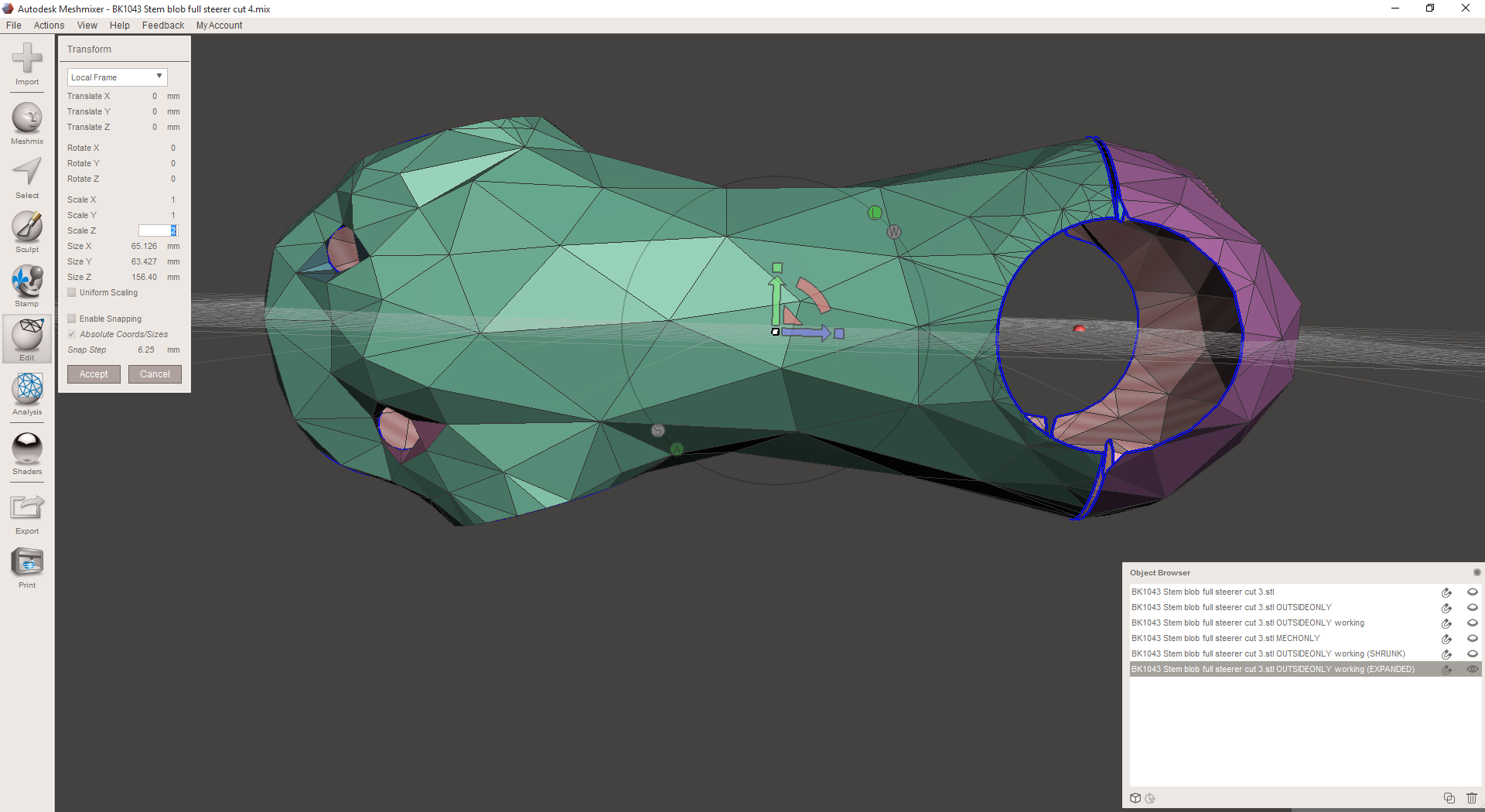
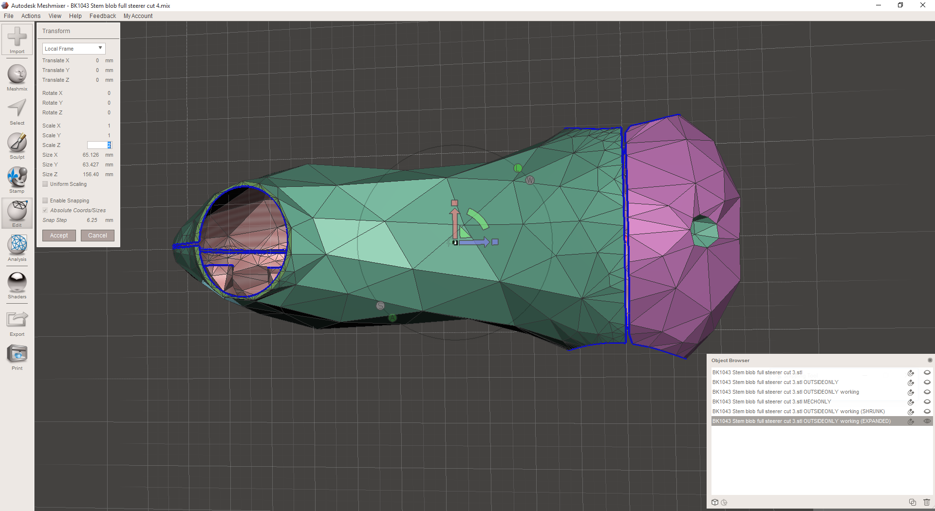
As you can see in the last few shots, the lattice has been stretched significantly. I've also remeshed a few of the higher resolution areas individually, evening them out a bit. Back in nTopology Element, you can see the difference between the old lattice (the last shot below) and the new one:
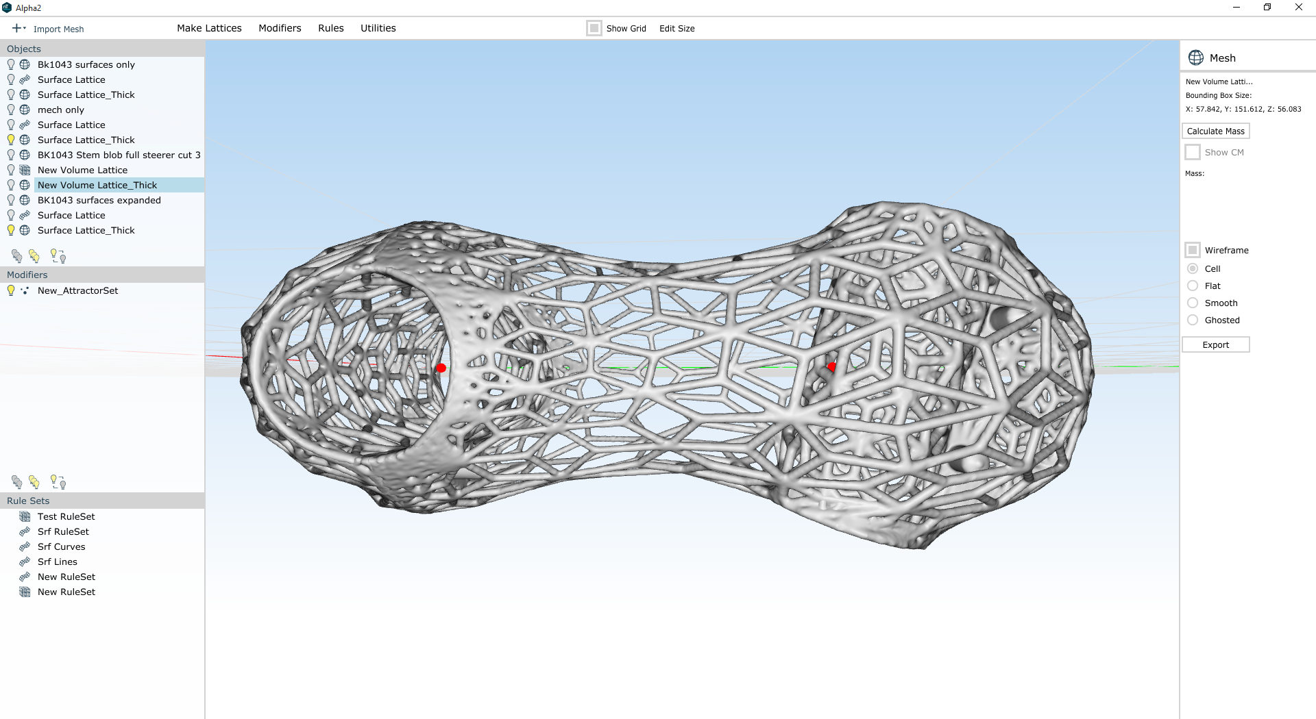
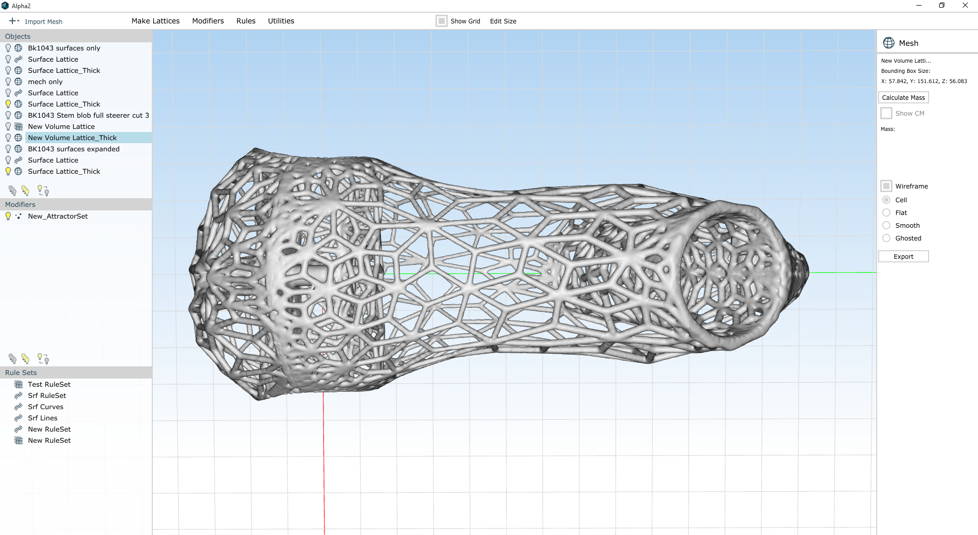
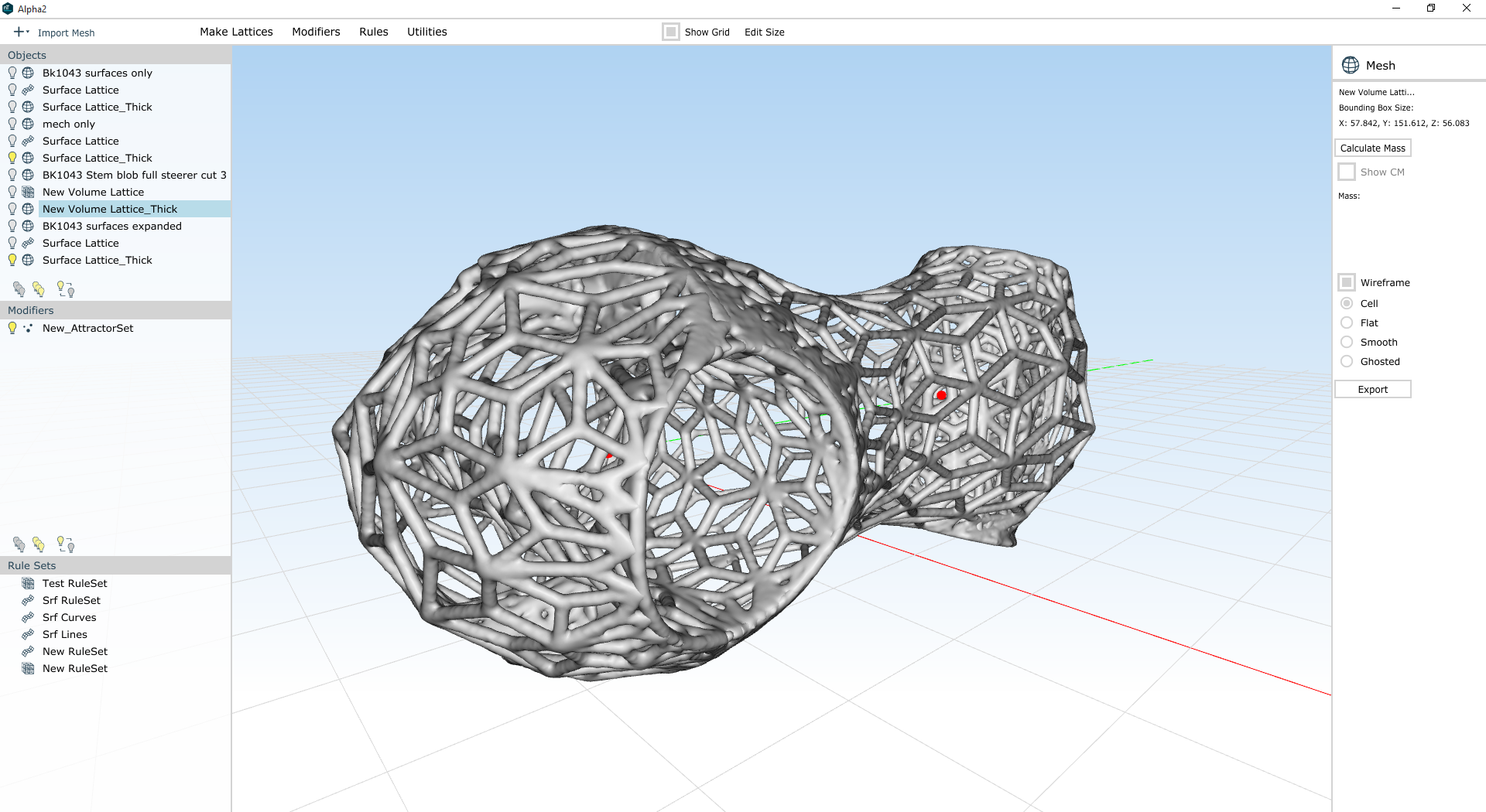
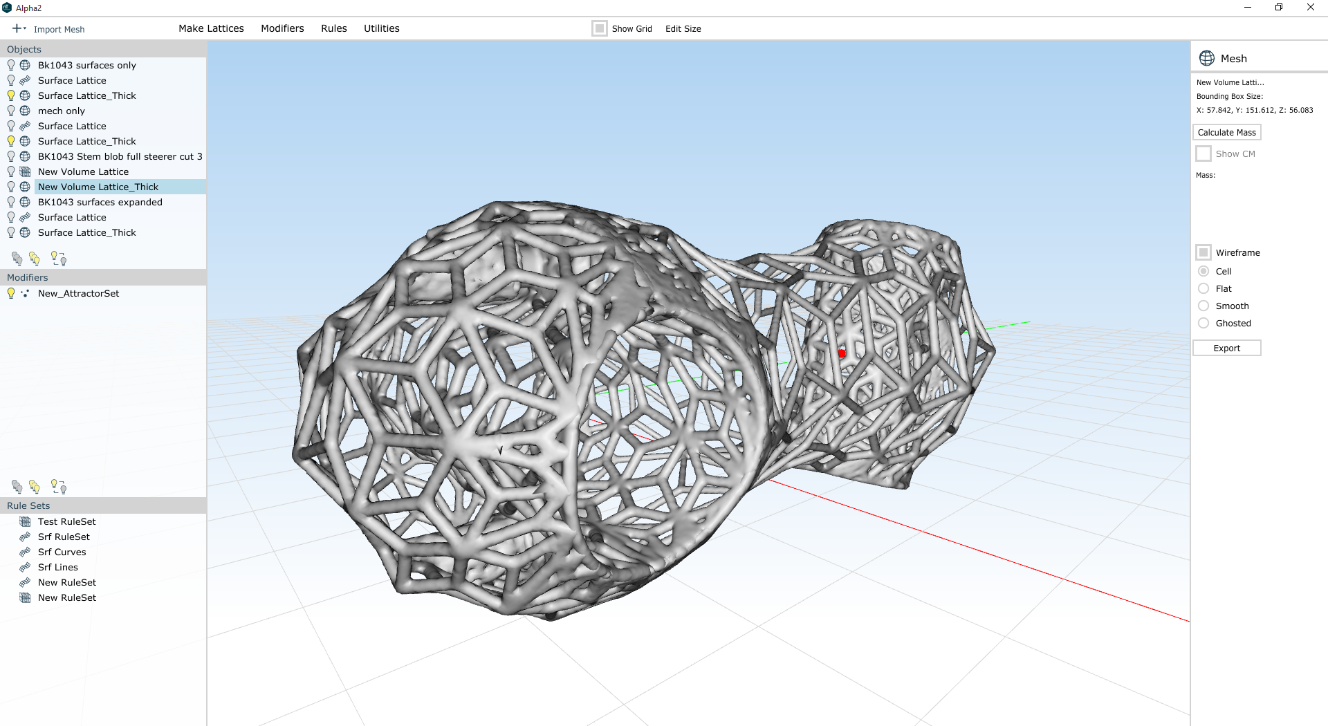
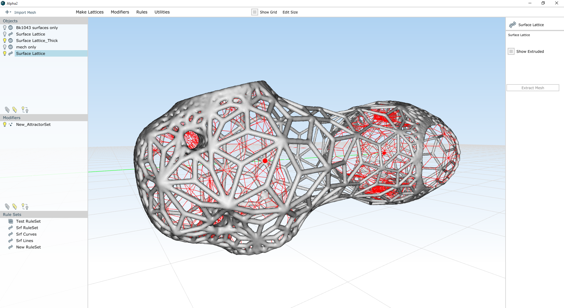
Meanwhile, I've used nTopology element to create (and warp) an Oct-Tet volume lattice for the interior of the part. This may look odd (and to be sure it needs some work) but a lot of these beams will be surprisingly useful once the whole part is put together. The red stuff here is a zero-thickness representation of the mechanical features' lattice structures; the white/yellow structure is the volume lattice:
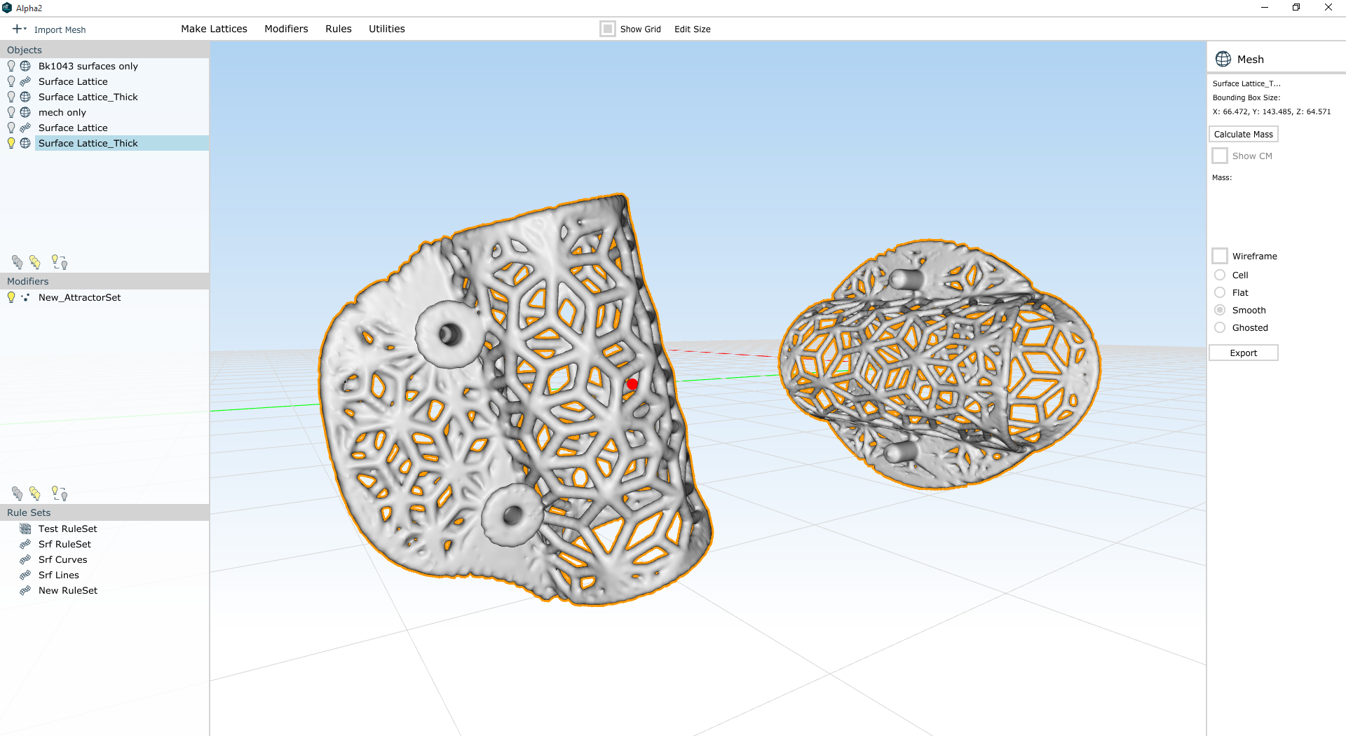
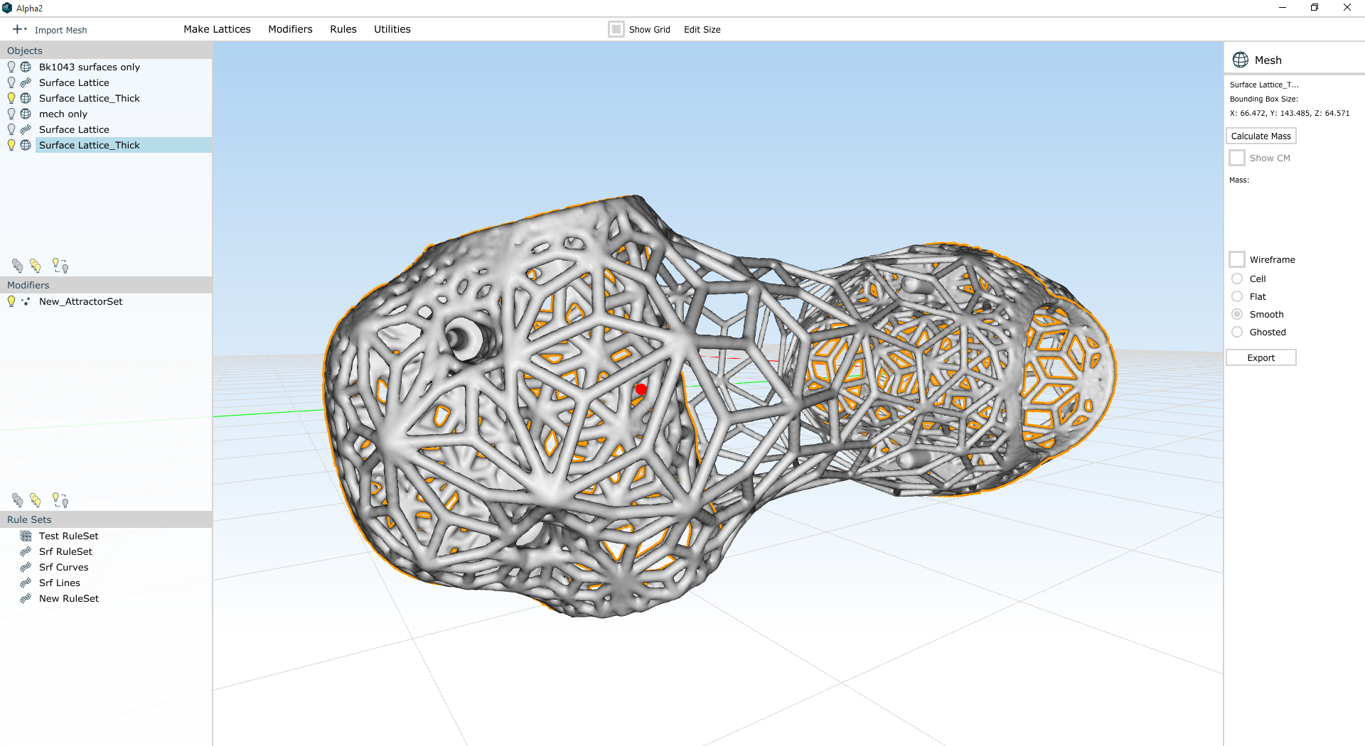
When you put the whole thing together, it starts looking pretty good:
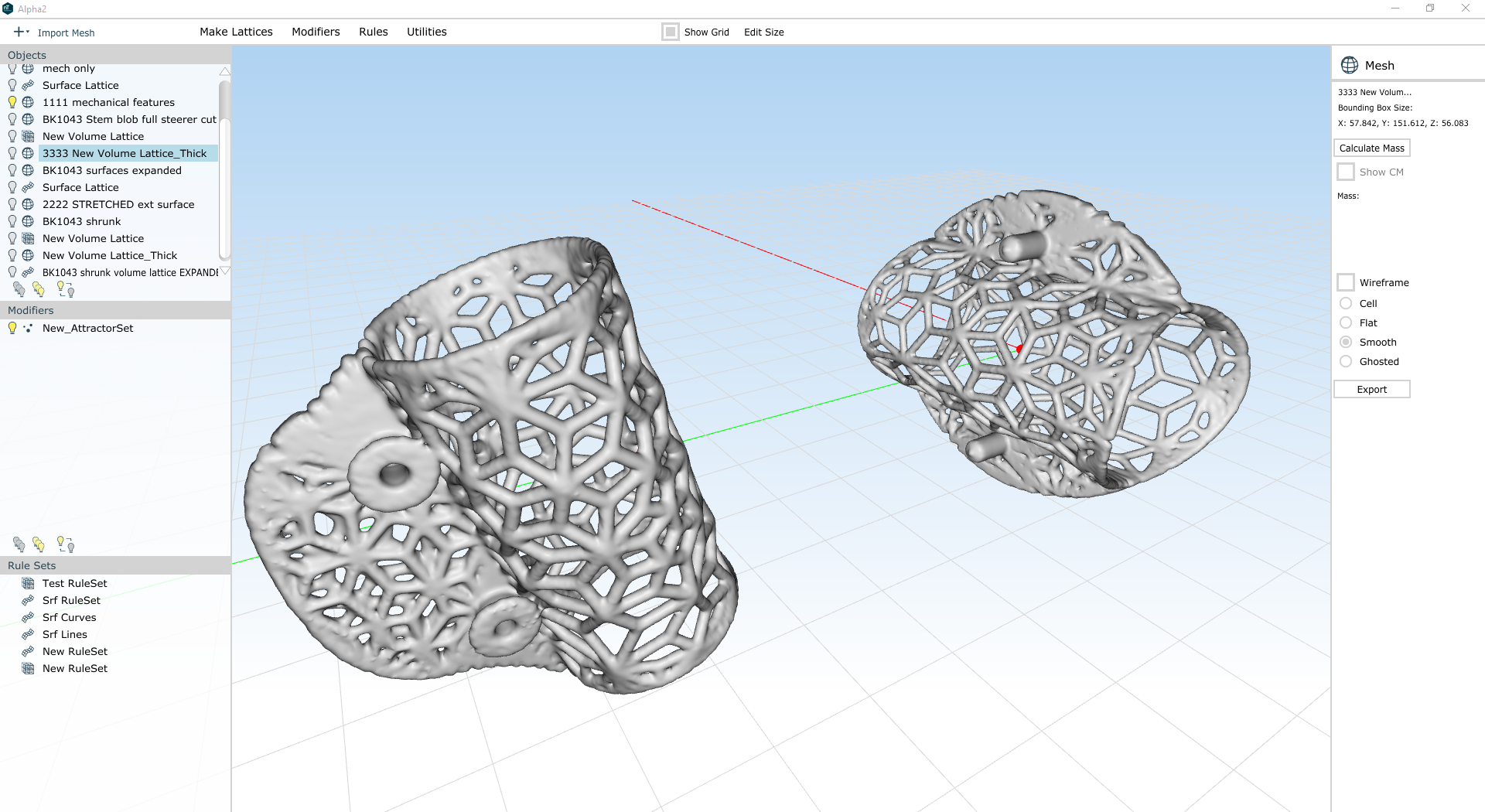
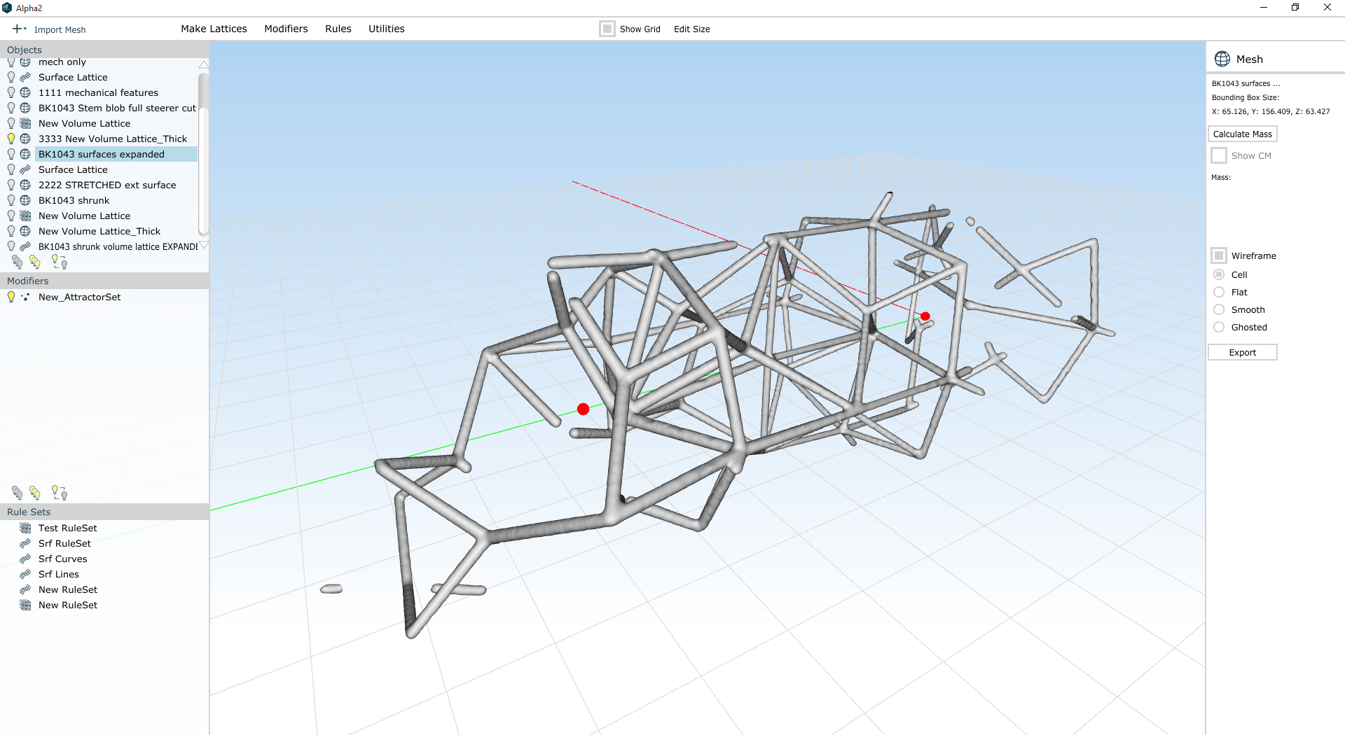
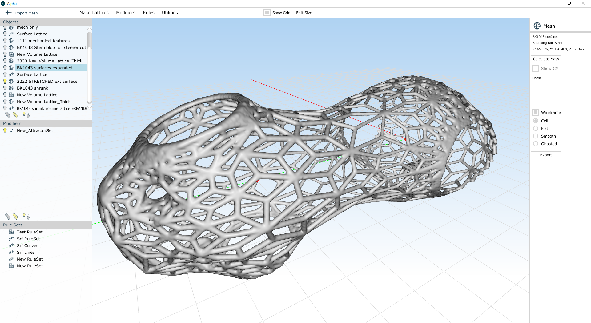
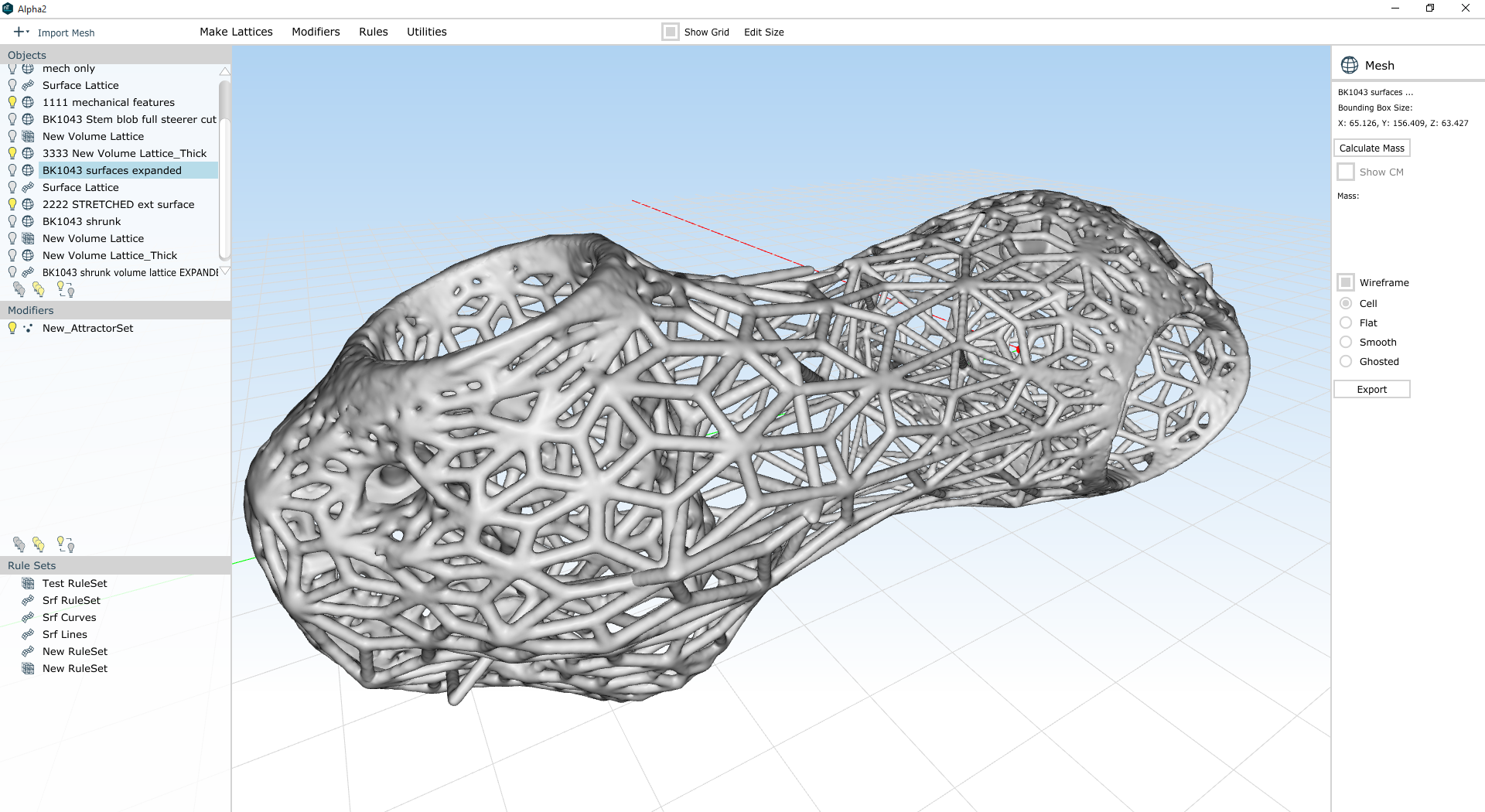
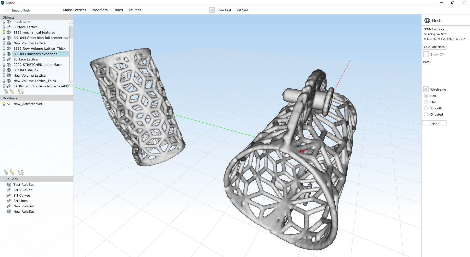
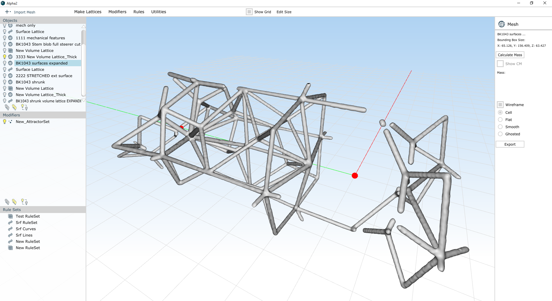
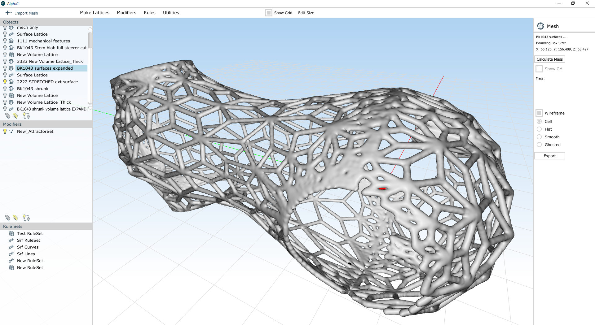
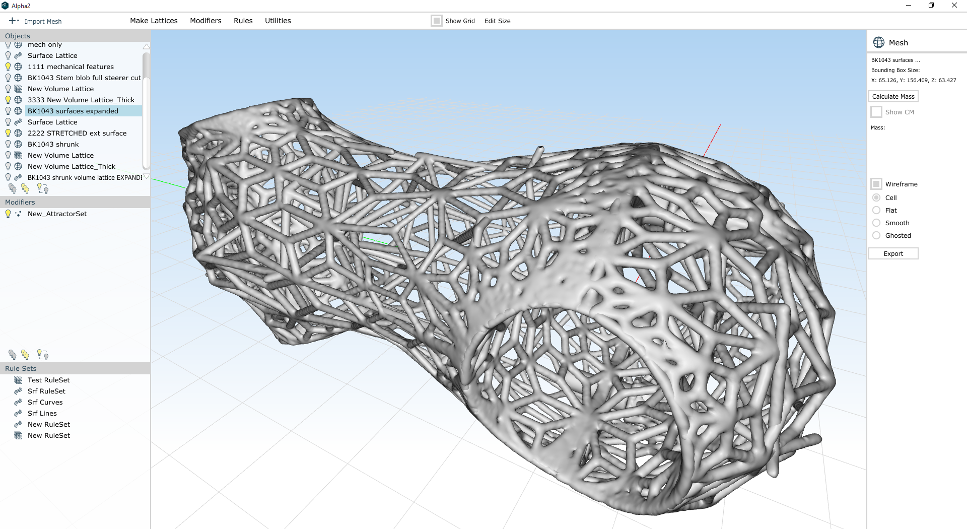
Now, there's still a lot wrong with this. There are a *lot* of overhanging faces. The threaded bolt holes aren't very well connected to the outer mesh, and there's probably too much material on all of the flat faces (where the slits/slots are). I'm also over my mass target - my total is 34.1 cubic centimeters, and my target was 27.7.
But there's a lot right with the design, too. My beams are about the right size throughout, and I've been able to (more or less) distribute my mass where it will matter most. And while the aesthetics of the part aren't exactly what I'd like them to be, they're not far off either.
So, a few things I need to work on:
- First, I need to make overhanging faces easier to eliminate. Some part of this *needs* to be happen when I remesh a surface (assuming I'm using the surface topology to determine the lattice topology). Ditto with volumes - I need to be able to stretch the lattice out so that it isn't horizontals all over the place.
- I also need to be more careful about directing my volume lattice where it'll be more effective. It's possible I should break it up into a few regions - some near the mechanical features, and one in the middle of the part - but I'm concerned that if I do that, I'll never get the two to tie together. Either way I need a denser volume lattice at the bolt holes, and I need to be able to tie the volume lattice beams up to the other regions of the part.
- I should probably play with modifying my mechanical features back in Inventor to make them more conducive to lattices. This might involve warping the clamp cylinders somewhat to reduce overhanging faces... or drilling the threaded holes through the part so that they connect to the exterior surfaces... or puncturing the flat faces so that they aren't as massive as they are in the current design.
Clearly, there's a lot to do here still. But I'm beginning to get the hang of this workflow, and hoping to have some printable (and extremely lightweight) designs to make soon :)
