A version of this saddle, but way cooler:
I've got a few other things going on right now, but this is one that I've been itching to do for a while. More soon :)
A version of this saddle, but way cooler:
I've got a few other things going on right now, but this is one that I've been itching to do for a while. More soon :)
As some of you may know, I like doing workshop-ish projects from time to time. This used to be more of a thing for me (my career went from construction to bicycle frame fabrication to running a prototyping shop), but today it's limited by practical constraints - primarily the fact that I live in Brooklyn and don't have a shop of my own.
But my desk retains a lot of its workshop origins, and I keep both tools and pieces of hardware that I'm developing nearby at all times. It's a bit ad hoc, but recently I've put a bit more thought into what I want in my home office - and some basic tools are definitely a part of that.
So a few months ago, I bought a granite surface plate to use for inspection (and, as you'll note from some of my blog posts, photography). I also cleared a bit of space on my desk for a few small tool chests (these need to be replaced with something more substantial), and recently I bought myself a special treat: A 3" Wilton Bullet vise.
I've coveted Wilton vises for years. They're known for being sturdy and well built, and they have the benefit (especially in my current situation, where space is a premium) of being small and having gentle edges. I must have learned about Bullet vises after I purchased my first real vise - a 6.5" Yost model that, according to my email history, I bought in 2006 - and for a long time I regarded them enviously.
Now that I'm setting up my own (tiny) work space, I'll be putting this guy on a yet-to-be-built (and yet-to-be-designed) desk in my apartment. I got it on ebay for $188, and spent some time this weekend (in my old shop in Southampton, which now lacks machine tools but is still mostly functional) taking it apart, cleaning it with Simple Green and a scrub brush, giving it a light coat of oil, and reassembling it.
The vise does have one defect: The cast iron swivel base is cracked, and needs to be repaired. I may end up doing this myself (my brazing setup is in pieces, but won't take *too* long to put back together), but given the other things on my plate right now I'd just as well get someone in NYC to help me out. If you or someone you know has experience brazing cast iron, drop me a line and I'll bring over beer and trade stories.
I'm excited for this. These vises are so cute and so functional - and it'll be great to be able to do a little more (light) work at home.
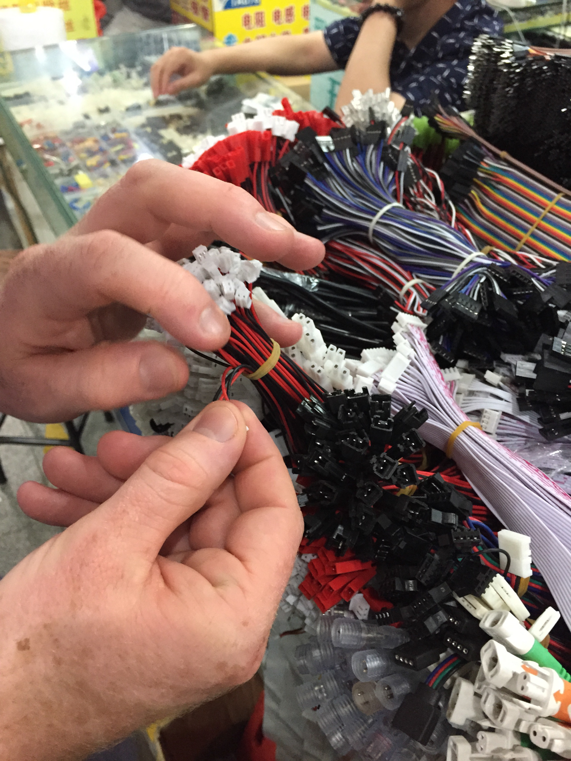
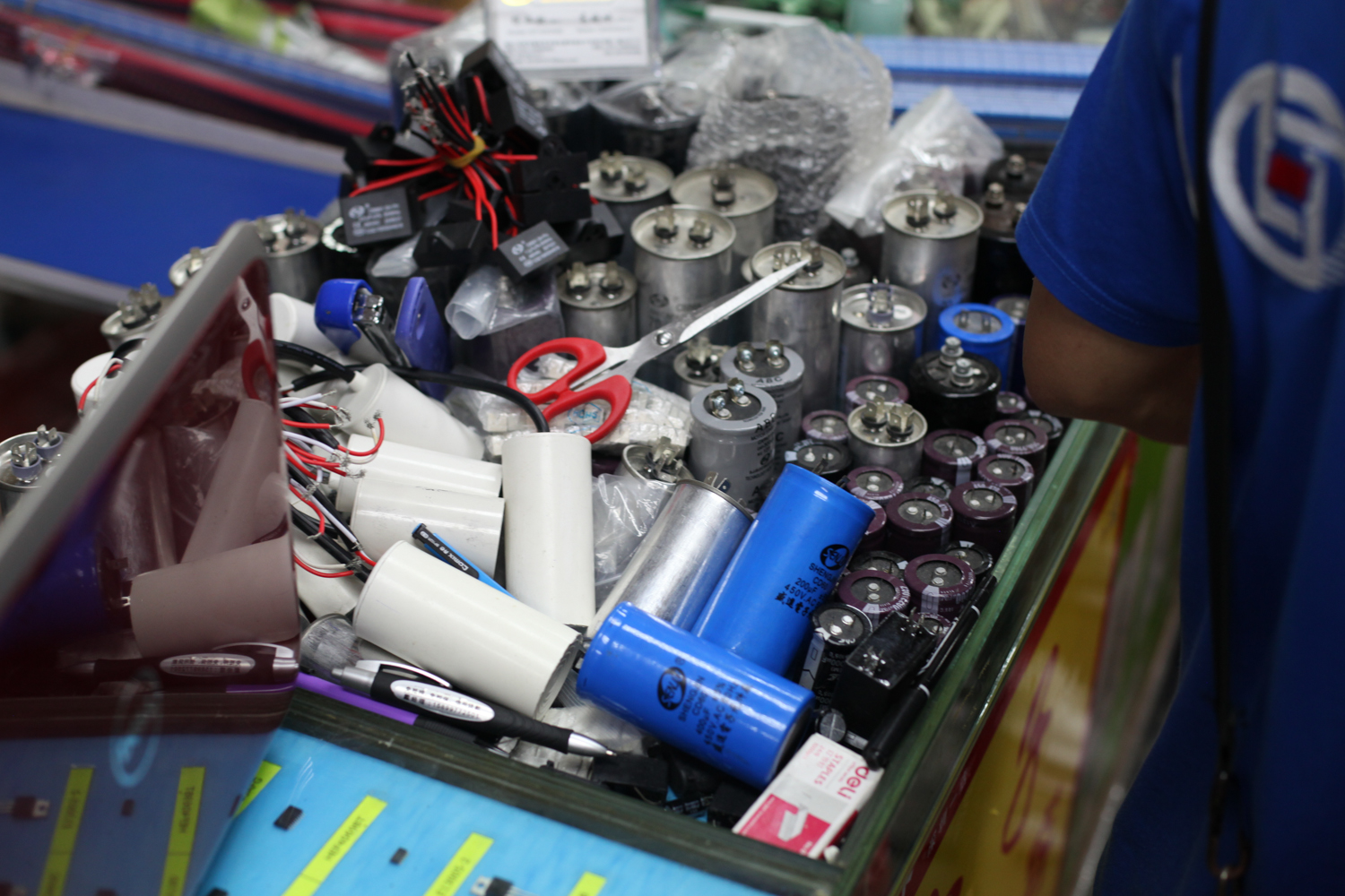
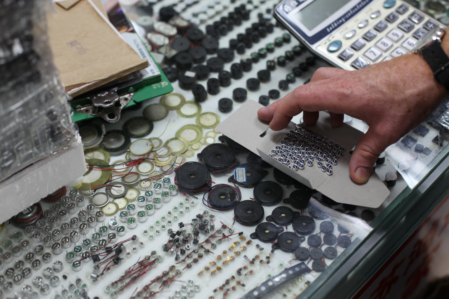
When Zach and I were in the Pearl River Delta for The Public Radio in late July, we took a few trips to the infamous Shenzhen electronics malls. A few notes:
As a final note, a rather remarkable thing happened since we returned from China. My old MacBook Pro had a hardware failure, and the problem appeared to be the hard drive cable (apparently they tend to go bad on my particular model). I ordered a new one on Amazon, and when a week went by (I hadn't really looked at the shipping time estimate), I checked to see its status. Well it turns out that the cable was sent to me directly from Shenzhen. I have no way of knowing, but I wouldn't be surprised at all if it came from one of these malls.
I've been thinking of the things I want to focus on in metal additive manufacturing, and came up with these two goals:
The reason I *don't* mention OEMs here is because I assume that if 1. and 2. are achieved, then the OEMs will be just fine, as they'll have a healthy supply of both engineering talent and manufacturing capabilities available to them. That's not to say that I don't want to help OEMs too, but in my opinion you can have a bigger long term impact (and help save yourself from the client-driven feature creep common in industrial solutions) if you keep small shops' needs in mind.
I have some initial thoughts on how I'd begin to address these, but I'm still in the process of developing them. If anyone has ideas, I'd love to chat about them - drop me a line!
A serious question - please post comments if you have thoughts!
Does the ratio of service providers to OEMs in an industry correlate indirectly with the defect rates in its critical components?
In other words, as the manufacturing processes required to produce a product become more reliable, is production shifted away from OEMs?
You won't be surprised that my question relates to metal AM - and the degree to which OEMs can generally outspend (in both R&D and acquisitions) the smaller job shops. When a critical process in the industry is unreliable, OEMs can invest the capital expenses to either solve the problem (through R&D and often resulting in trade secrets) or acquire companies who have. But as the process matures, smaller service providers can be more competitive, as their overhead is (citation needed) in many cases lower.
As a result: Until the process (for example, metal powder bed fusion) is fully industrialized and reliable, it's very difficult for small shops to enter the market. But once the technology is well understood, mom & pop shops are able to flourish.
A concrete example: Today, OEMs like GE, Airbus, and Philips dominate the metal additive industry, and the proprietary R&D they do makes insourcing components more cost competitive than buying them from service providers. If you start a job shop today, it might be 12-18 months before it reliably creates revenue. But if & when additive becomes a more predictable process, the time to revenue (and profit) will be shortened, and OEMs will find it increasingly attractive to outsource their parts.
^ This is a half baked theory - I'd love to hear your perspective!
Edit:
I'm trying to get a better handle on my blog's audience, and how on earth they ended up here. If you don't mind, would you please tell me a little bit about yourself?
This month I'm doing a deep evaluation of Materialise Magics 19 and SG+, and trying to understand both the major features of the software and the philosophical perspective that Materialise views additive manufacturing through. I'll post more thoughts on the overall process chain later, but for now I wanted to work through some of the observations I've had in my first encounters with Magics.
For background: The cost of this software is in the neighborhood of $20,000. It's generally NOT purchased by people who don't themselves own industrial (i.e. $250k+) 3D printers. But I feel very strongly that without some knowledge of how it works, independent designers will be doomed to creating inefficient, difficult to manufacture designs. So, I signed myself up for a 30 day demo and got working :)
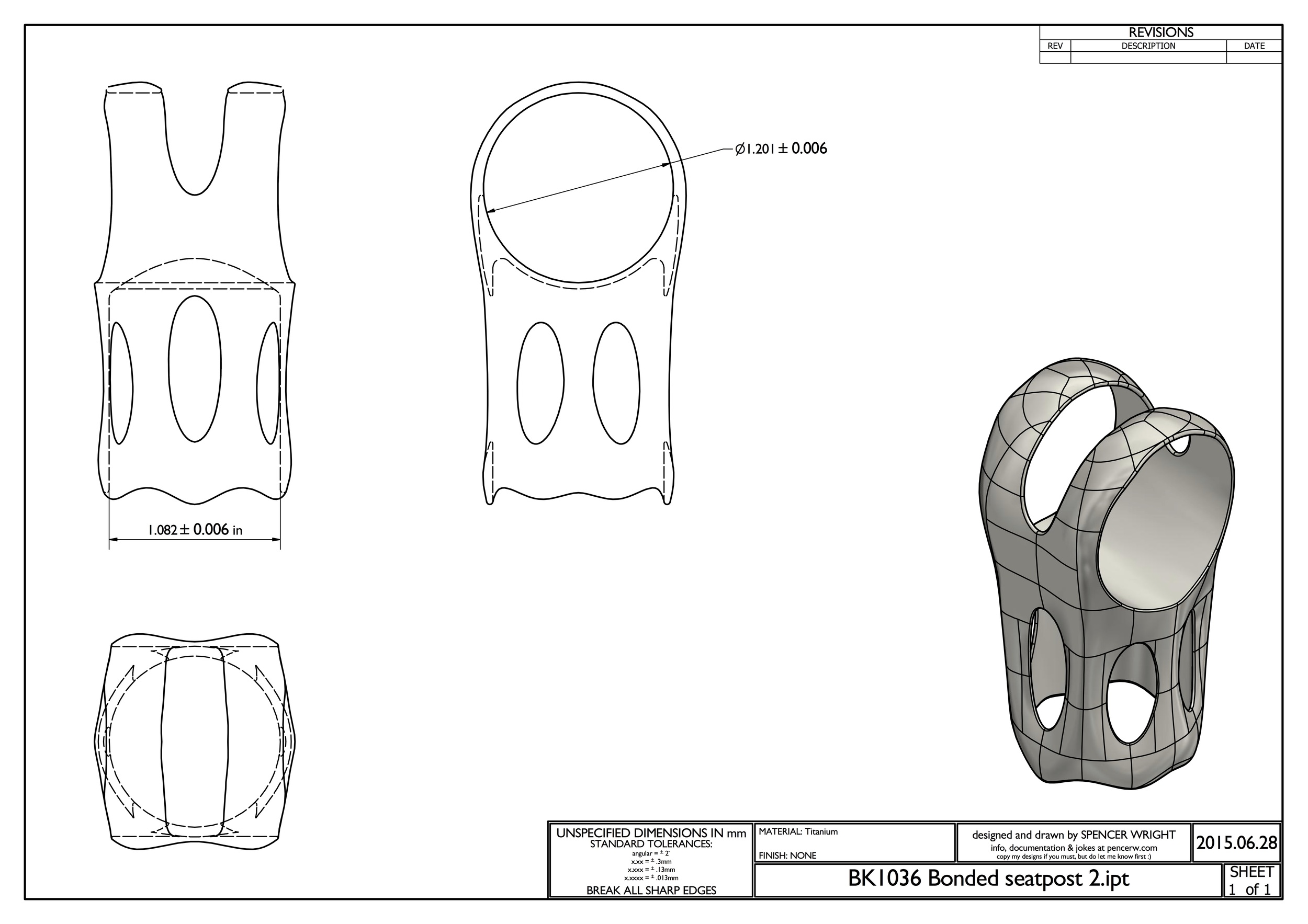
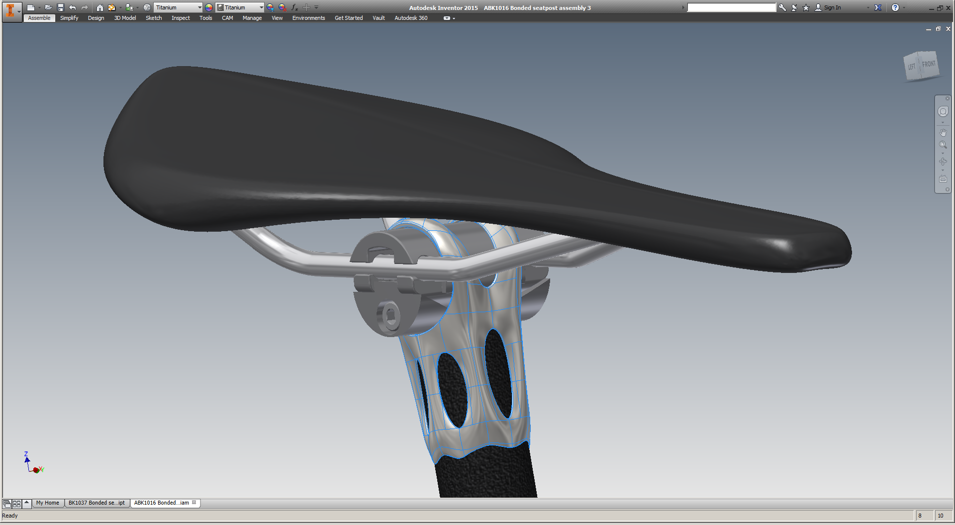
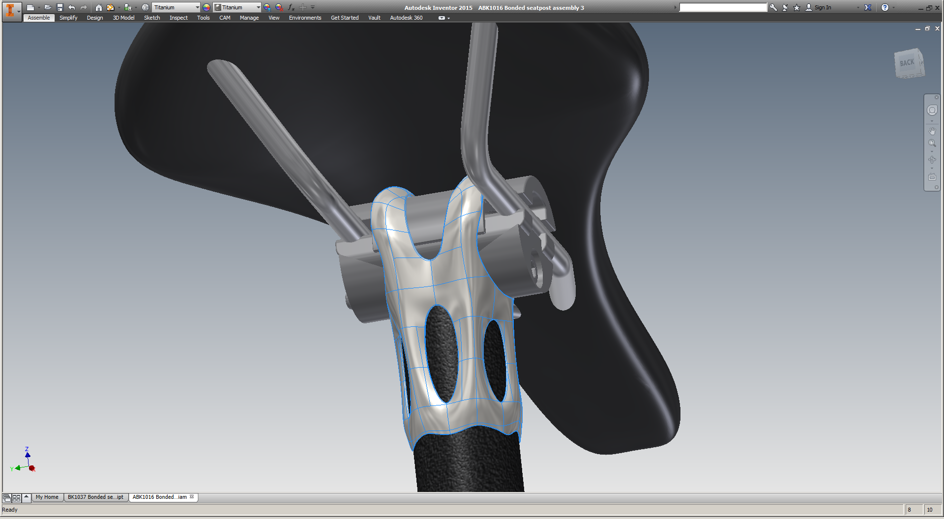
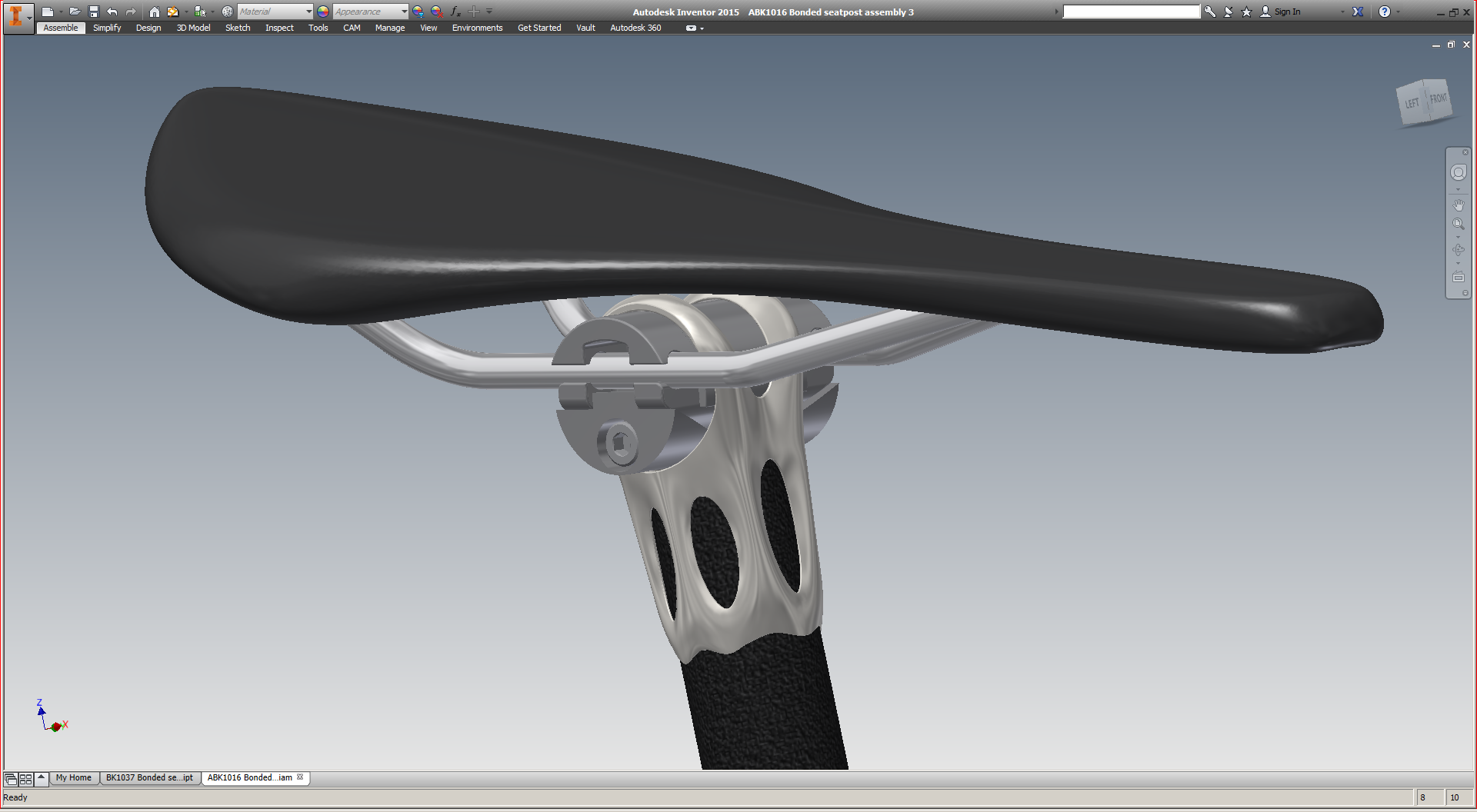
Note: Throughout this post, I'll be showing screenshots of my titanium seatpost part. I've already had one of these parts EBM printed by Addaero, and expect to have versions of it printed in both EBM and laser metal powder bed fusion (which I'll refer to as "DMLS" throughout this post) in the near future. In order to simplify the descriptions below, here's a key to the part's features:
I believe Magics to be a classic example of a piece of industrial software whose development has been driven by customers who are large, powerful, and often have divergent interests.
In many ways its functionality probably benefits as a result. Materialise has close relationships with a number of industrial 3D printing machine manufacturers (notably Renishaw, SLM, and EOS, all of whom have agreements in place to allow Materialise access to their machines' build parameters, and develop build processors to work natively on those machines). They also collaborate closely with many of the large manufacturers (both OEMs and service bureaus) who build 3D print parts on the machines that Magics supports. Through these relationships (and through their own internal parts business), Materialise can get an up close view of what their biggest users need out of the software, and prioritize their efforts accordingly.
On the other hand, by relying heavily on key accounts to drive the product's development, Materialise gives up much in the way of product vision - accepting, instead, a steady stream of feature creep. Every additional feature (while I'm sure they're all valuable) makes the entire application more difficult and clunky to use, and it often feels like Materialise has given two different customers two distinct ways of doing the same thing - simply because each one demanded that the workflow fit their way of working. This kind of path is ubiquitous around the world of industrial software, and Materialise is, to be fair, ultimately at the whim of its (enormous) industrial stakeholders. But as someone coming in from the outside, the result feels schizophrenic.
The core issue is that independent designers like myself are seen as customers, while Magics' development is driven by client relationships. Again, this isn't Materialise's fault, and nor is it ipso facto bad. But I don't believe that the incentive structures that drive Magics' development are optimal for the industrialization of additive manufacturing, either. I'll explore this topic more in a later post; for now, just ponder this. In the meantime, here are my initial observations of how this big, important, and powerful piece of software works.
One important note: Materialise is a member of the 3MF consortium, which is working to create a file format which apparently contains "the complete model information" within "a single archive." My hope is that 3MF allows for more of the process chain to be accessible from a single interface, and that Materialise is a key part of that development. I'm looking forward to learning more about 3MF in the near future; stay tuned for more.
Magics has two or three ways to do basically everything. At the top of the window is a drop down menu bar. It changes depending on context, but generally has a lot of functionality; in the default view, it has eleven menus - a mix of standard stuff (File/Edit etc) and context dependent stuff (Fixing/Scenes etc).
Directly below that is a tool bar, which mostly contains standard tools (undo/redo, Print 2D, Zoom/Pan/Rotate, etc). As far as I can tell, every command in the tool bar is also accessible via the menu bar AND via keystrokes & mouse gestures.
To the right of the tool bar is a series of tabs, which toggle the appearance of another tool bar below. These are a bit more context dependent, and as far as I can tell the correspond 1:1 with what's shown in the "Tools" drop down menu above. Most of these functions, though, *can't* be accessed by keystrokes or mouse gestures.
Overall, Magics' multiple, competing UIs are not unlike most of what's out there in industrial & B2B software today. Most companies (including Materialise) tend to bill this as a feature: the user can interact with the software in a wide variety of ways (keystrokes, mouse gestures, drop down menus, or toolbars), so almost anyone will be able to get comfortable with the interface quickly.
Personally, I prefer opinionated UIs in industrial/B2B software. The best one I'm aware of is McMaster-Carr's, which is built specifically for MRO professionals and makes everyone else adjust their mindset to that of someone looking for replacement parts. I'm not an MRO professional, but once you figure out how they work, the experience is wonderful.
Magics doesn't act this way, though. The UI doesn't guide me at all; it simply offers a multitude of options, and lets me decide which one I prefer.
Magics' "Orientation Optimizer" is very straightforward, and seems in some cases like it'd be useful. I used it only briefly, but to be honest I had already decided more or less the orientation I wanted the part to be printed in. As it happens, the Orientation Optimizer confirmed my plan, but I take that confirmation to be a bit of a false positive. As I discuss below (and have written about extensively in the past), setting an orientation angle really requires an understanding of the part's design intent and manufacturing life cycle, and Magics lacks these. As a result, it can only optimize for the factors that it understands: in this case, some combination of Z-height, XY projection, Support Surface, and Max XY Section. I chose the middle two of these, and Magics gave me exactly what I already knew I wanted.
This tool is probably more useful in high mix environments (service bureaus), but most of the people in the industry I've spoken to say that when they use it, it's just as a starting point; the final orientation is almost always set by a human being.
Generating support structures in Magics is really straightforward; it's possible (though almost definitely not ideal) to simply choose a machine, plop a part on the build plate, and hit "generate support." Magics has some understanding of the technology you're using (in my case, either EBM or DMLS), and it creates support geometries that are (reasonably well) tuned for the process.
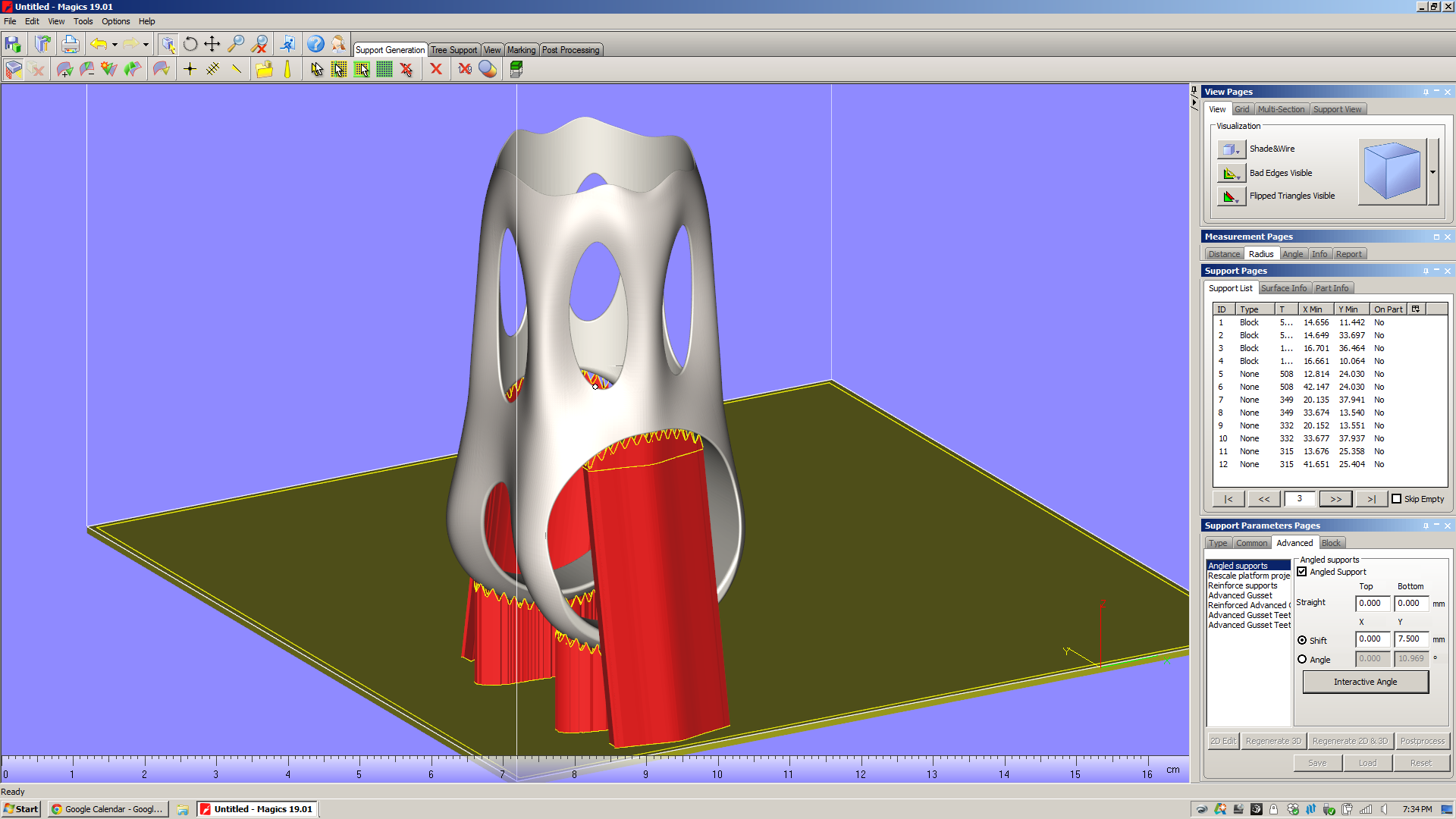
But before you even get that far, Magics has a nice feature that allows you to preview which surfaces will need to be supported - the "Supported area preview." Presumably this would be used while the operator is setting the part's orientation in the build chamber. It allows you to view downfacing edges as shaded, and it shades them on a color gradient depending on what you want to see. Here I'm looking at the underside of the part, and varying the angle that Magics highlights:
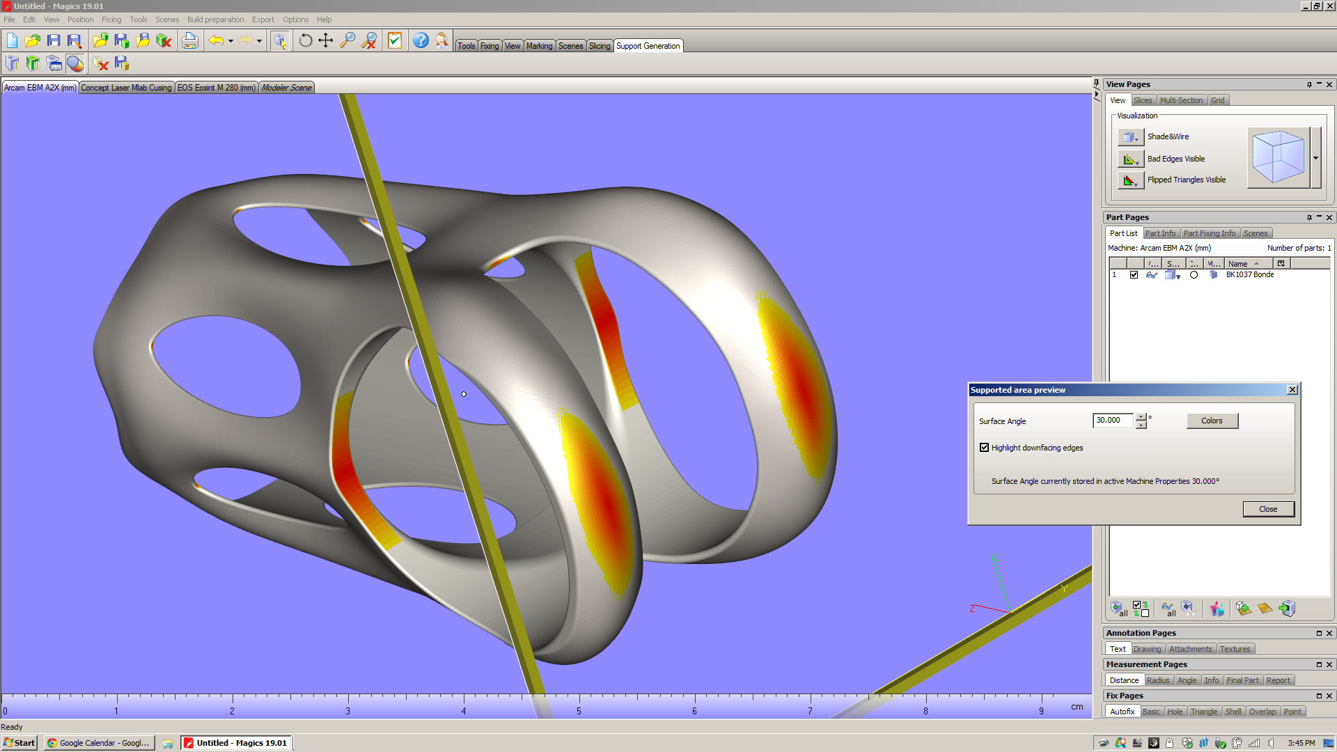
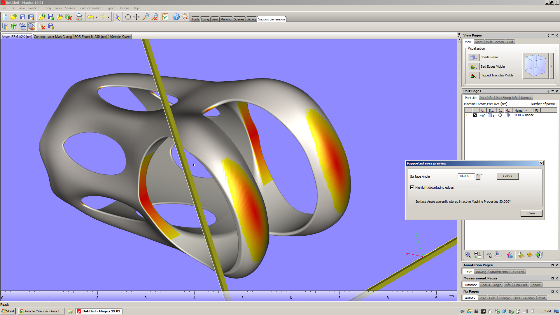
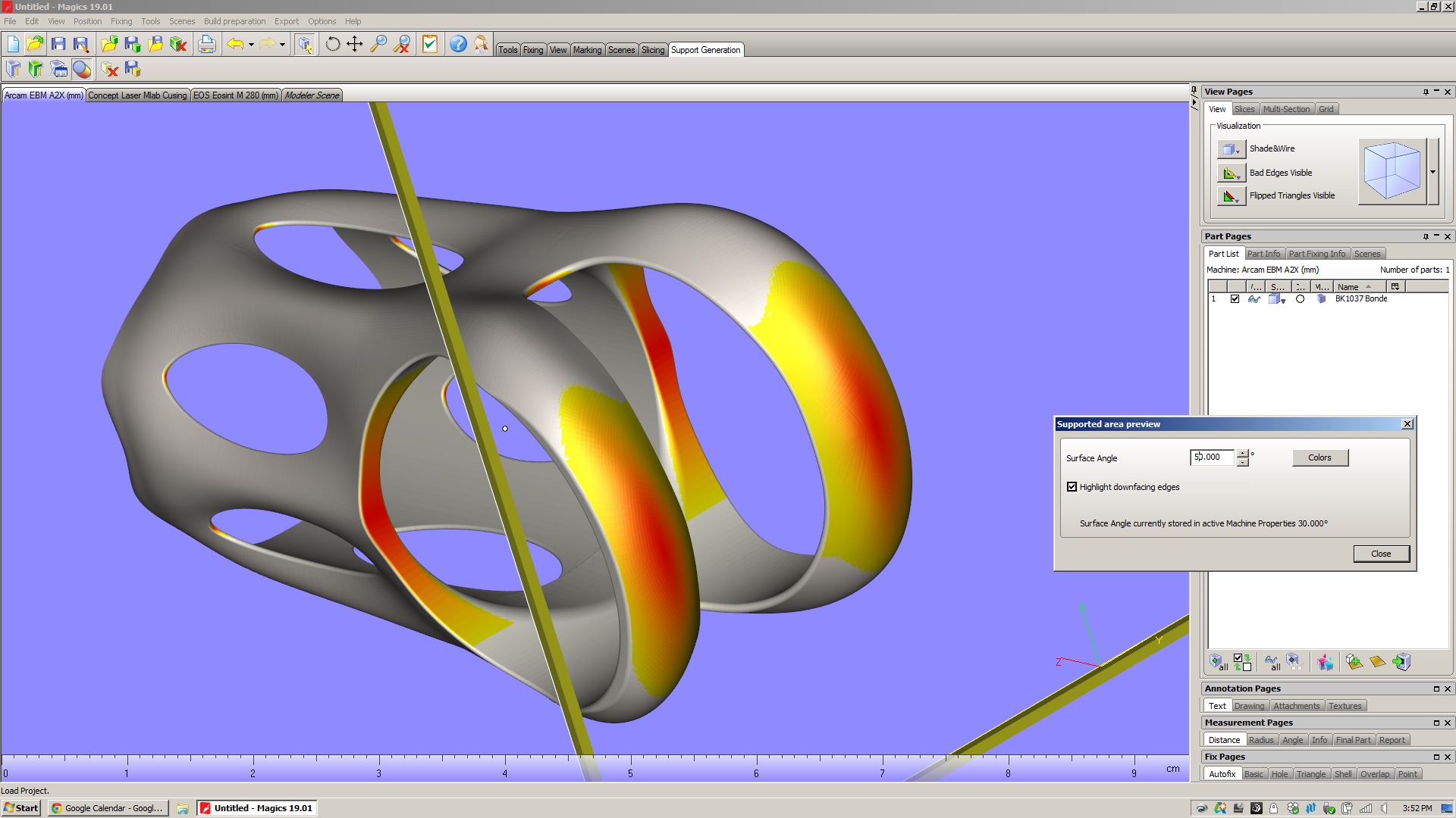
On my part and in this orientation, there are two large areas that need support structures (inside the saddle clamp cylinder, and from the shoulder straps down to the build platform). But if you look closely, you can see that there are also a series of tiny areas with downward facing surfaces:
For comparison, the cross sectional area of a "medium" grain of sand (as described by ISO 14688) is about .4mm^2. Which is to say that these are relatively small surfaces. My hope is that even though they face downwards, they won't require support structures at all.
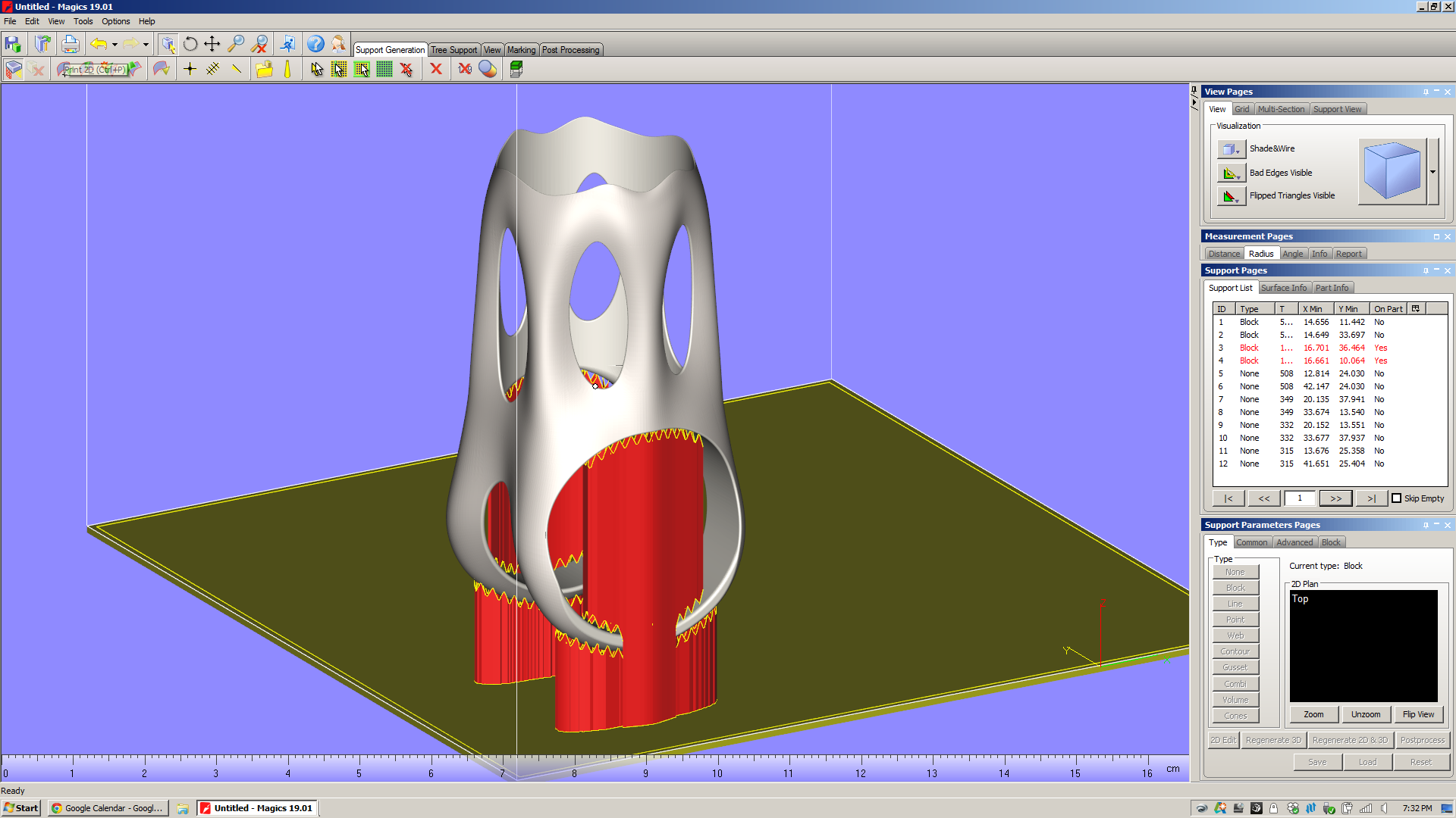
When you enter the support generation module and hit "generate support," Magics simply looks at the faces that face downward, chooses a support type that's appropriate for the surface size & shape, and projects that support directly downward. Here are the automatically generated supports for both my part in EBM and DMLS:


Throughout Magics' UI, there are "tool pages" on the right of the window that offer a variety of context dependent functions. When you're in the support generation module, there's a section of "Support Pages" there that let you analyze and modify the support structures in your build. Looking at the support pages in the pictures above, you'll notice that I've got the "Support List" page open, and that there are 12 supports listed in that view. For each of these, a variety of data is displayed: ID; type of support; some basic geometrical data, and an "On Part" column. You'll also notice that the supports that are "On Part" are keyed red in the list. This is a very useful piece of information: those supports, when they were projected downwards, ended up falling onto the part itself. The result is that when the part is printed, those supports will tend to be more difficult to remove. In the case of the MLab build above, supports 3 and 4 run the full inner diameter of the saddle clamp cylinder. In the Arcam A2X build, supports 3 and 4 are in the same situation - but a whole series of point supports (7-12) are also partly trapped in the part's windows.
In my experience, this is *not* desirable. Especially with EBM, supports that fall onto the part itself are a real pain in the ass to chip out (for a bit of context, see the photos I took of the first parts I had EBM printed). In addition, they tend to make the surface they're hitting rough, and as a result the part often requires more post processing.
In order to avoid this, I need to modify the support parameters. By going into the "Advanced" section of the Support Parameters Pages and checking off "Angled supports," I can pull the two big Block supports (ID 3 and 4) away from the part:
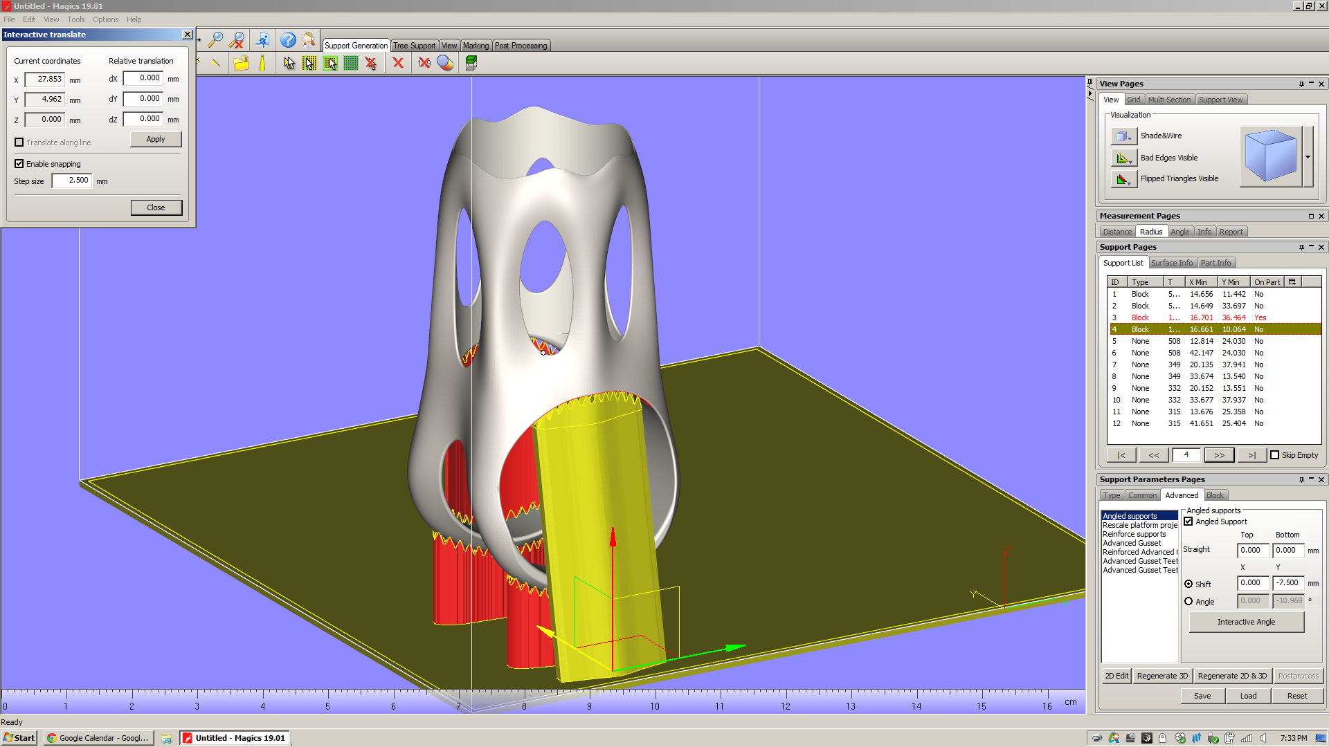
(I'm working on similar edits to the EBM build, but want to get a little clarification from Arcam on those point supports first.)
I can do a variety of other things to these supports, including "Rescale platform projection," which essentially flares the support in/out as it goes down to the platform. There are also a slew of parameters (hatching, hatching teeth, teeth synchronization, perforations, etc) which seem mostly designed to make the supports easier to remove from the part. All of these can be preset in the Machine Properties screen (which, frustratingly, isn't accessible when you're in Support Generation mode) or adjusted on a support-by-support basis from the "advanced" tool pages.
To be sure, I'm only scratching the surface on Magics' support generation features here. Magics will let you play with a *ton* of support parameters. I get the impression that there's a lot of nuance here, and that there are many parameters that you'd only play with in edge case builds. Regardless, the number of possibilities generated by varying just a few of the options is staggering; in order to know how they affect part quality, you'd need to run thousands upon thousands of test builds.
Eventually, it's very likely that Magics (or whatever replaces it) will have thermal & residual stress simulations built right into the software. Today, however, machine operators have remarkably little info about the finished part before they actually print it. Except...
This is a key part of the additive design-for-manufacturing process. Knowing how long a part will take to print is a *huge* factor in what it costs, and is critical in comparing two build configurations for the same part.
Magics has a build time estimator, but it's not plug-and-play. Instead of shipping pre-loaded with estimates of how long a given machine will take to build a part, Magics requires the user to run "Learning Platforms" - and you need to own your own machine to do that. And, of course, I don't own a metal powder bed fusion machine.
The reason for this is that in order to estimate build time, you need to know how both the slicer and scanning strategy work - as well as mechanical factors like scanning speed and recoating time. And while certain machine manufacturers (see below) share this information with Materialise, for many it simply isn't worth it. They see those process parameters as valuable, and don't see the benefit of sharing that data with a third party software developer. Moreover, most of them can provide very accurate build time estimations in their own software, and the manufacturing engineers that use the machines take it as given that they need to use that at some point in the process anyway.
This strikes me as a big failing. Magics needs a way of sharing data about their builds: a public repository of machine parameters and build times. Without that - or without, on the other hand, convincing the machine manufacturers to share that data themselves - Magics is left with a huge disconnect between the build setup and the end product. This undercuts Magics' claim to be "The link between your CAD file and the printed part." If it lacks basic data on build speed for the most common machines in the industry, what exactly is it linking to?
So: As of the time I'm writing this, I've got emails out to a handful of the biggest metal powder bed fusion machine manufacturers in the industry, asking for Magics learning platforms. If anyone out there can share that data with me, please send me a note!
My demo doesn't include these, but they're worth touching on. For a few big machine manufacturers (Renishaw, SLM, and EOS), Materialise has developed build processors that are tuned to those machines' capabilities and specifications. Presumably, these companies provide Materialise with in-depth data about how their machines work, some of which is either patented or proprietary. Materialise then builds software modules that, through a few intermediate steps (the most notable of which are slicing and subdividing/hatching), produce a job file that can go directly to a machine.
Materialise bills the build processors as reducing complexity in the manufacturing life cycle, and allowing both Materialise and the machine manufacturers "to focus on their core competencies." Having not played with them myself, I can't really comment. I hope to learn more soon.
To reiterate: It's my impression that Materialise built Magics to fill a really big hole in the existing work chain, and the bottom line is that that work chain is something that no single party (let alone Materialise) created. It's also, in my opinion, *not* the right work chain for the future of additive manufacturing, and Magics' role in it highlights a lot of the problems in the industry today. Here are a few things that I noticed that Magics can't, for various obscure and not-so-obscure reasons (many of which are decidedly *not* Materialise's fault), do.
This is something I've touched on in previous posts, but it struck me again when I was in the "supported area preview" screen. It's *very* likely that I could, with a relatively small amount of work, edit the underlying geometry in order to reduce the number of supports needed significantly. But I'm not aware of a way of showing downfacing regions in solid modeling software (Solidworks/Inventor, etc), and it's rather cumbersome to bounce back and forth between Magics and Inventor to try to optimize the design for additive.
All across the industry today, I hear people talk about design software that understands the intent of the designer, and responds to accommodate it. This may be feasible in the near future, but the bottom line is that Magics (as it stands now) is *not* part of that process chain. Once a designer transitions from parametric modeling to surface tessellations, all of the geometry data is lost. If manufacturability feedback (like the supported area preview screen) is provided in software that reads surface tessellations (as Magics does), then going back to edit the underlying parametric model is *always* going to be cumbersome - and necessary.
In all additive processes that I'm aware of, surface finish will vary significantly depending on the orientation of a surface relative to the build direction. Given the layer thickness of the printed part, this is relatively straightforward to simulate - not to a high degree of precision, but with a good amount of accuracy, at least. Magics doesn't do this, and it leaves me feeling like I'm missing a key piece of information about the printed part. Sure, I can imagine what the part will look like if I just think about it for a minute, but it does strike me that having some indication of areas with high stepover (which will occur wherever a surface is oriented close to the XY plane) would be really helpful - and not particularly hard to implement (caveat: everything I said above about feature creep, etc).
This may seem like I'm splitting hairs, but I think it's worth reiterating: Magics bills itself as "The link between your CAD file and the printed part." It is NOT concerned with the end product, which in almost all cases will have additional (subtractive) processes performed on it.
Why does this matter? When I had this part EBM printed recently, both the saddle clamp cylinder and the seatpost cylinder came out undersized. I know now that one of two things needs to happen there: either I need to compensate for the printing process in the underlying model (by making the designed dimension larger than I actually want it to be), or I need to remove material from the as-printed part (by machining, grinding, or similar).
Magics doesn't know any of this. If it did, it might be able to give me intelligent advice on what surfaces to take extra care with - and which I should ignore, as they'll be machined away in the end regardless.
In the end, Magics is a piece of CAM software - but it only deals with one step in the production chain. Changing this is a monstrous, complex task, but it's one whose impact will be hugely positive.
Magics is pretty cool - it does a *ton* of really useful stuff. You'll note, also, that I'm basically not interested at all in its "fix" feature, which (I'm told) is used a lot with models that come out of Rhino.
But it's also representative of a lot of what's going on in industrial additive manufacturing today. This isn't Materialise's fault; it's just the way things evolved, and is the result of (I'm sure) a lot of collaboration, competition, and plain old hustling (all of which I fully support) in the industry over the past few decades.
Regardless, Magics is a place where you can see a lot of the implicit assumptions that industrial additive manufacturing has been built upon. More on this soon.
I've been thinking a lot recently of a passage from Chuck Klosterman's book Eating the Dinosaur. In it he talks to the documentary filmmaker Errol Morris, and the topic is about the act of being interviewed by people. This is a bit of a long passage, but I think it's a fascinating topic - and a relevant one to me, as I've learned *so* much over the past few years by simply asking people if I could ask them questions, and then going ahead and doing so.
For the past five years, I've spent more time being interviewed than conducting interviews with other people. I am not complaining about this, nor am I proud of it - it's just the way things worked out, mostly by chance. But the experience has been confusing. Though I always understand why people ask me the same collection of questions, I never know why I answer them. Frankly, I don't know why anyone answers anything. The obvious explanation is that the interviewee is hoping to promote a product or a concept (or the "concept of themselves," which is its own kind of product), but that's reductive and often untrue; once a media entity makes the decision to conduct and produce an interview with a particular somebody, the piece is going to exist regardless of how the subject responds to the queries. The interviewee can say anything, even if those sentiments contradict reality. They can deliver nothing but cliches, but the story will still run. On three occasions I've consciously (and blatantly) attempted to say boring things during an interview in the hope of killing the eventual article. It only worked once. But this type of behavior is rare. Most of the time, I pretend to be interesting. I try to frame my response in the context in which the question was asked, and I try to say things I haven't said before. But I have no clue as to why I do this (or why anyone else does, either).
During the summer of 2008, I was interviewed by a Norwegian magazine writer named Erik Moller Solheim. He was good at his job. He knew a lot of trivia about Finland's military history. We ate fried pork knees and drank Ur-Krostitzer beer. But in the middle of our playful conversation, I was suddenly paralyzed by an unspoken riddle I could not answer: Why was I responding to this man's questions? My books are not translated into Norwegian. If the journalist sent me a copy of his finished article, I could not read a word of it. I don't even know what the publication's name (Dagens Naeringslif) is supposed to mean. I will likely never go to Norway, and even if I did, the fact that I was interviewed for this publication would have no impact on my time there. No one would care. The fjords would be underwhelmed.
As such, I considered the possible motives for my actions:
Why do people talk?
Why do people talk? Why do people answer the questions you ask them? Is there a unifying force that prompts people to respond?
Errol Morris: Probably not, except possibly that people feel this need to give an account of themselves. And not just to other people, but to themselves. Just yesterday, I was being interviewed by a reporter from the New York Observer, and we were talking about whether or not people have privileged access to their own minds.
CK: Privileged access?
EM: My mind resides somewhere inside of myself. That being the case, one would assume I have privileged access to it. In theory, I should be able to ask myself questions and get different answers than I would from other people, such as you. But I'm not sure we truly have privileged access to our own minds. I don't think we have any idea who we are. I think we're engaged in a constant battle to figure out who we are. I sometimes think of interviews as some oddball human relationship that's taking place in a laboratory setting. I often feel like a primatologist.
CK: Do you feel like you know the people that you interview? Because I never do. It seems like a totally fake relationship.
EM: I don't feel like I know myself, let alone the people I interview. I might actually know the people I interview better than I know myself. A friend of mine once said that you can never trust a person who doesn't talk much, because how else do you know what they're thinking? Just by the act of being willing to talk about oneself, the person is revealing something about who they are.
CK: But what is the talker's motive? Why did you decide to talk to the New York Observer? Why are you talking to me right now?
EM: Well, Okay. Let's use the example of Robert McNamara. Why does McNamara feel the need to talk to me - or anyone - at this point in his life? Because there's a very strong human desire to do so. It might be to get approval from someone, even if that person is just me. It might even be to get a sense of condemnation from people. Maybe it's just programmed into us as people. McNamara also had this weird "approach-avoidance" thing: He agreed to do the interview because he assumed I was part of the promotion of his [then new] book. I called him around the same time his book was coming out, and he thought it was just part of that whole deal. When he realized it was not, he became apprehensive and said he didn't think he was going to do it. But then he did, and it went on for well over a year. In fact, I continued to interview him for a long time after that movie was finished, just because I found it very interesting.
CK: But why did McNamara keep talking?
EM: He said he enjoyed talking to me. That was his explanation.
I think a lot of people don't realize the power of this. If you want answers, ask questions. People reply way more often than you'd expect.
Learning new software is fun. This is me after a few hours playing with Materialise Magics 19 and SG+.
I've made a few modifications to the standard build:
It's worth noting that this part is too far off the build plate right now - I'm still trying to get used to Magics' UI, and figured it didn't matter for now. I should probably also orient the part at a slight angle from vertical (see my recent post, here, for more details on this); again, I'll play with that a bit more later.
Oh, and I probably want to add additional reinforcements to the short ID, to make sure that it prints round. I'm looking at a few methods of doing this, most of which would require some work back in solid CAD (Inventor), or *possibly* some volumetric mesh generation software (like nTopology).
I'm definitely still getting used to Magics' philosophical perspective on the additive process chain, too. I have some thoughts on what this is, but will play around more before I share them :)
Stay tuned.
Just a little teaser:
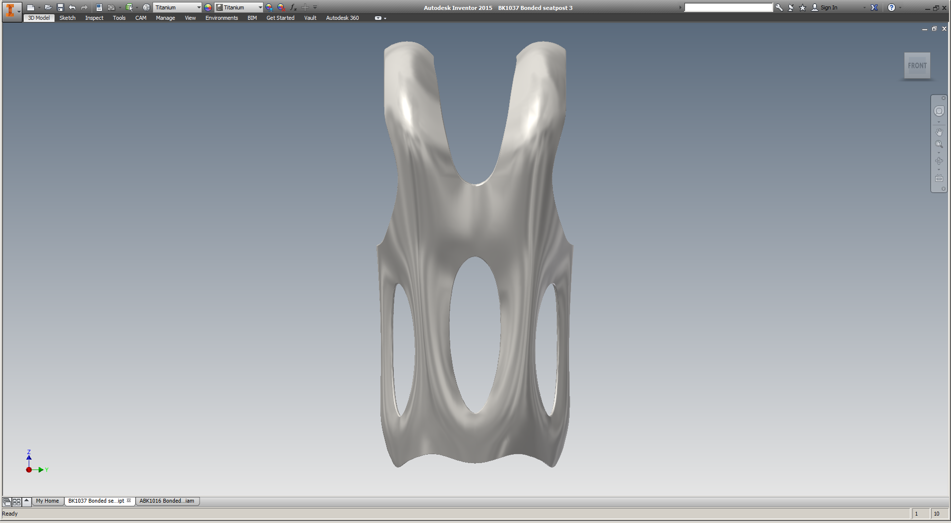
This week, in addition to the networking I'm doing (remember: I'm a free agent now, and directing my efforts toward finding the best path for myself in metal additive manufacturing), I'll be diving deep into Materialise Magics 19, the industry standard software for metal 3D printing build processing. I'm excited to learn more about its capabilities, and will share more later this week. I'll be spending most of my time working on orientations & support structures schemes for my titanium seatpost head, seen here in Magics' simulation of an EOS M280:
Magics bills itself as "The link between your CAD file and the printed part." It's used by OEMs and service bureaus alike to prepare design files to be printed - often times on the very machines that I've been building parts on (one, two) over the past year. In most cases, Magics imports an STL file. It then can be used for three big chunks of work:
Lastly - and of particular interest - is the SG+ module for support generation in metals. This would fall somewhere between (and across) numbers 3 and 4 above, and involves creating solid and mesh support structures that anchor the part to the build plate and provide thermal sinks to ensure a successful build. The SG+ module is a critical part of the metal 3D printing process chain today. It's used extensively across the industry, and engineers who are skilled at support generation are highly prized.
This week I'll be exploring these features (especially build prep and SG+) extensively; stay tuned for updates.
When I went to Taiwan last year with Brilliant Bicycle Co., I wrote a few posts that described the trip & what we saw there. But I never linked to Jacob Krupnick's videos of the trip, which do a much better job of relaying the mood & feel of the trip. So, here goes.
First, the tire factory (see my notes here):
Second, the cardboard box factory (see my notes here):
Third, the fork factory (see my notes here):
Fourth, the frame factory (see my notes here):
Fifth, the final assembly shop (see my notes here):
Sixth, the saddle shop (no notes from me, sorry):
Seventh, the paint shop (ditto):
This week, while in Seattle, I had the pleasure of visiting Amazon and talking with some folks there about Amazon Business. To prep, I spent a bit of time reflecting on the B2B ecommerce world, and how the major players in it have approached & prioritized their efforts there. I've written about both Amazon and B2B ecommerce a bit before, but what's below clarifies my thoughts on their position in the ecosystem significantly.
To an outsider, Amazon has always struck me with two core messages:
Also of note: Amazon has always seemed to target specific audiences in its external messaging. Most prominent to me are:
What’s missing in the list above is business customers. I’ve bought plenty of business related stuff on Amazon, but it’s usually been from my personal account, and the shopping experience isn’t aware (or doesn’t care about) the context shift that I (presumably?) go through when I clock in and out. The “Recommendations for you” sections switch over, but it’s on a visit-by-visit basis. Amazon treats me as a person, and it simply recommends that I look at things that are similar to what I looked at recently.
Now, I’m sure that plenty of businesses have Amazon accounts that are just for business purchases. I worked at one such business a few years ago, and again recently. In both of these cases, I got the impression that (and please, pardon the pseudo Christensen here) Amazon had trickled *up,* being used first at home (whether by the person in charge of purchasing, or someone who was bugging them to buy something) and then later at work. As a result, it always made sense that the Amazon product we used at work was the same as the one we were using at home. I was used to it, and it has gotten *so* easy to buy stuff for personal use there, and changing my mindset a bit to use Amazon for business stuff was really very easy.
The arrangement worked well. When I was running a prototyping shop, I made a *lot* of purchases from McMaster-Carr and MSC and Rutland. Those companies’ catalogs were tailored for the work we were doing, and they (especially McMaster) do *such* a good job of providing a consistent browsing, purchasing, and fulfillment experience, that once you get used to their system it’s hard to imagine life without it. But there were plenty of times where I used Amazon too, especially when it came to items that fell more on the “office supplies” end of the spectrum. Amazon’s search features are really good, and it’s great to have ratings sometimes as well. Amazon’s product discovery system is dramatically different from those of the industrial suppliers, and there are a lot of cases where I’ll hit the wall with one system and really just want a change of pace.
This is worth highlighting:
It’s also worth noting that these companies each take a different approach to knowing/caring who (or what type of entity) their customers are:
If it’s not clear, I *like* these differences. I enjoy living in a world where companies put philosophical approaches to commerce up for debate, and let consumers decide which they prefer. The variety is good, and I find myself enjoying trying to use each to its most powerful effect. But the differences are worth noting, and it’s fun (and possibly useful) to project outward where each of these perspectives might lead in the future.
Dear reader —
This report is an update to my experiences in metal 3D printing; it describes a good chunk of what I’ve been working on over the past four months. While I’d like to say that it stands on its own, I think there’s some context — especially if you’re just beginning to explore metal 3D printing — that can be gained from reading my earlier posts (starting with my long "Bin of broken dreams post") first.
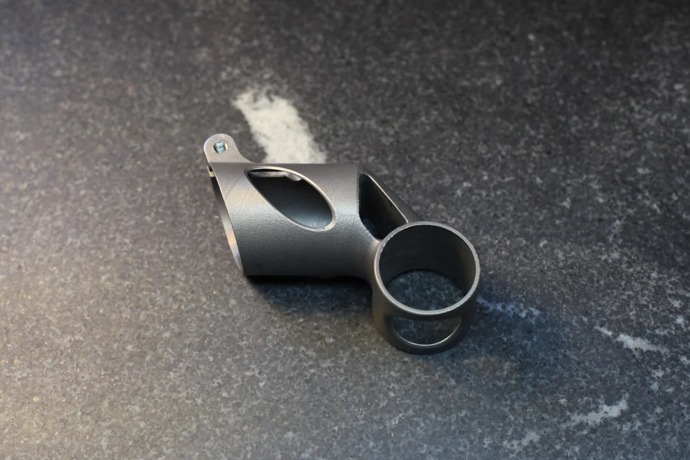
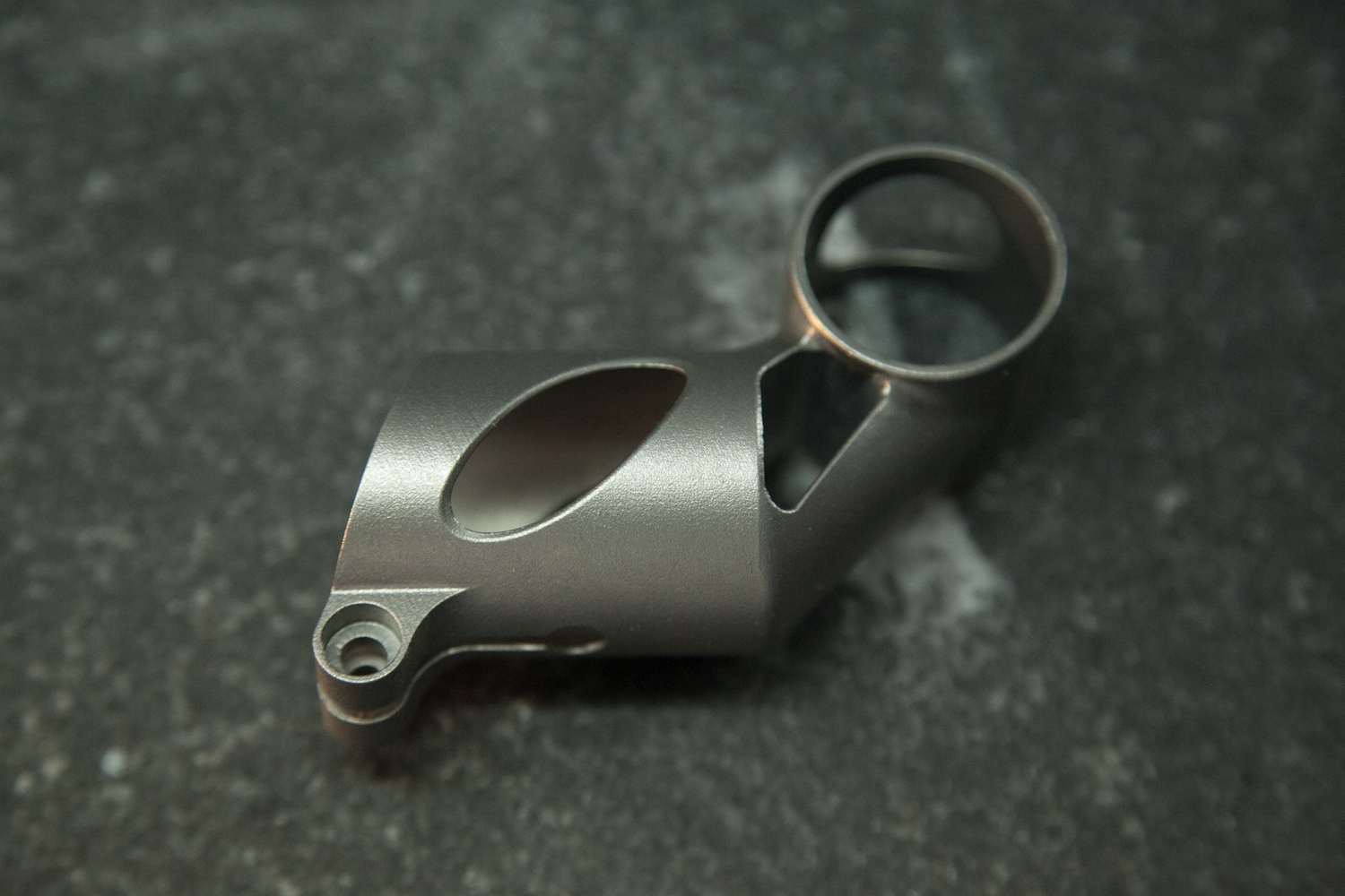
For background: I believe that functional, engineered consumer products made by additive manufacturing are an inevitability. In order to prepare myself for that inevitability, I’ve been developing a line of bicycle parts made by metal powder bed fusion, a process that’s used extensively in aerospace, medical, and tooling applications. My last post described the difficulty and constraints I’ve experienced in part geometry and build orientation. Since then I’ve turned a corner, and today I can say that I’ve successfully designed, built, and tested a functional product — which at last puts me in the position of needing to learn from success.
As I’ve documented the process — and frustrations — of developing metal 3D printed parts, I’ve been pleased and surprised at the number of people who’ve reached out to me to commiserate (n.b., if you’re reading this and want to do so yourself, please drop me a line). Without exception, they have expressed solidarity. “We share all of your frustrations,” one person said. “I have been through the same pain as you,” said another.
One of these people was Tom De Bruyne, General Manager at Layerwise. Layerwise is a Belgian company which was started out of the Catholic University of Leuven (one of the premier centers of additive manufacturing research); it was acquired by 3D Systems in late 2014. They’re famous for being one of the few service providers who built their own laser metal powder bed fusion machines, and have a ton of experience making 3D printed parts at both prototype and production scale. We struck up a conversation, and soon agreed to work together.
While popular opinion would have you think that quantity is a non-factor with 3D printing, the realities of running a service bureau are much to the contrary. To job shops, quantity is a critical factor; if a part will be produced at large volumes, every detail of its design and manufacturing life cycle must be examined. If, on the other hand, you’re printing a tool — or a prototype of a part that will be manufactured conventionally — then most shops will focus on getting the first print right without modifying its underlying geometry.
My project falls somewhere in the middle: while my design is certainly imperfect, there are many aspects of it which are very close. Moreover, it poses challenges (most notably its opposing cylinders, oriented 90° apart, and also its thin-wall construction and bolt boss) that will exist throughout any redesign, and solving them now will only improve my ability to deal with them in future iterations.
At the current juncture, the key questions to test are:
In practical terms, the first question boils down to whether we can build a part that can be installed on a bicycle. This means two things: maintaining inner diameters which are round and dimensionally accurate to within +/-.006", and having a bolt boss on the long cylinder which, when tightened, is capable of securing the part to a bicycle’s seatmast.
My last prototype was built on its side, and the long cylinder’s aft wall distorted as it was sintered. We added a series of solid ribs in order to counteract the built-in stress in that wall, but it ended up like a game of whack-a-mole: each reinforcement just moved the stress somewhere else. A new approach was needed.
Unlike most of the US job shops I’ve spoken to, Layerwise bundles together many low-volume customer orders into each build; my part was printed alongside a handful of other titanium parts in one of the 15–20 machines that Layerwise designed and built themselves. This means that Layerwise is able to process a large value of parts at once, even if they’re only building prototype quantities of each design.
This poses a significant challenge: if one part fails, it can jeopardize many customers’ orders. To mitigate this risk, Layerwise constantly monitors a slew of process signatures, and can adjust machine parameters on-the-fly if they detect problems. They’re also working on a layer-based deposition control & verification system (the details of this are secretive, but it sounds similar to the optical tomography systems that other machine manufacturers are working on today). Still, each part is evaluated carefully beforehand in order to anticipate and avoid failures. Especially for short-run prototypes, it’s usually better to over engineer the support structures (and ensure a successful build) than skimp out and need to rebuild the part later.
Layerwise is secretive about their custom-built machines, but they did tell me a few details. They each contain a single laser, and are built around roughly the same form factor (275mm x 275mm x 420mm) as most of the industrial machines on the market today. I also understand that Layerwise uses a recoater blade (unlike 3D Systems’ ProX line, which uses a roller), though I couldn’t confirm whether it’s a hard material (like the high speed steel blades that most EOS machines use) or a soft one (like the polymer wipers often used on Concept Laser machines). They’re able to print in about 15 materials, with the majority of their work being done in titanium. They monitor temperature, pressure, and oxygen content on-the-fly, and are working on additional variables — including full melt pool analysis.
Layerwise has in-house wire EDM, and has a daughter company that does 5-axis CNC machining. But most prototype parts, including mine, are finished by hand. When validating a part for production, Layerwise tests the full manufacturing lifecycle, building multiple full batches of parts and sending them out to be post processed. Once they’ve validated the process, they will in some cases hand off production to other 3D Systems divisions.
I worked with Martijn Vanloffelt, a project engineer at Layerwise, to prepare my part to be built. He used a few key tricks:
In order to maintain roundness in the saddle clamp cylinder (the shorter of the two cylinders, which was was going to be oriented more or less parallel to the build plate), Layerwise reinforced the inner diameter with three serrated discs.
They also oriented the part slightly off-axis in both the X and Y axes. This brings me to a point that’s worth highlighting: In metal powder bed fusion, a part’s orientation has a number of effects. First of all, any surface with an angle of less than about 45° (depending on material) must be supported. As a result, it’s generally better to orient a part so that all overhangs are as steep as possible.
But in addition, one must consider the angle between the part and the recoater blade. If the part lifts up at any point during the build, the recoater blade will strike it. The longer the area of contact is, the worse the result will be. Some machine manufacturers offer alternative recoaters to lower this risk (3D Systems ProX uses a roller; EOS offers a carbon fiber brush; Arcam uses a metal comb; and both Concept Laser and SLM offer soft polymer blades), but most use a piece of high speed steel (or, in the case of older EOS machines, a ceramic blade) to spread powder across the build platform. Regardless, it is usually better to orient parts slightly off axis in the XY plane, so that the blade doesn’t contact the part’s walls all at once.
Orienting parts off axis can also help improve surface finish. When a cylinder’s axis is aligned in the XY plane, the top face will exhibit an undesirable stepped appearance; my earlier prototypes all had this feature. When a part is oriented off axis, the surface finish is generally more consistent.
I should note that none of these techniques is guaranteed to work in all cases. Layerwise has a lot of experience building a wide variety of geometries, and has developed a sense of how to anticipate and deal with issues as they come up. I got the impression that the techniques they used on my part are things they’ve used in the past, but each design is different — and even a tried-and-true method of dealing with one design isn’t guaranteed to work well on another.
The Layerwise team also put a lot of care into generating mesh supports. Like most of the additive metal industry, Layerwise uses Materialise Magics for their final build prep, and they’ve developed expertise in exploiting the software in creative ways. I’m not able to share a detailed description of the supports Layerwise created for my part, but I can say (and anyone in the industry could confirm) that they were needed in four areas:
Layerwise took great care to orient the part such that it didn’t require support structures inside the hidden voids in its center section. This is something that designers and project engineers alike need to think about as a part heads into production. Not only can powder bed fusion not make fully sealed voids (if you printed a sealed sphere, the entire center would be full of trapped, unmelted powder at the end of the process), but many geometries will require support structures in areas where they’re difficult or impossible to remove. For instance, a Klein bottle could be printed in metal — but no matter how you oriented it, there would likely always be support structures stuck inside its fat end. Because of the angles in my part, it was possible to avoid this — but a different design might not fare as well.
The first part Martijn printed was a big step forward: The build completed successfully without collapsing. However, a new problem arose. The windows on the seatmast clamp area caused the two “leaves” of that cylinder to twist as they were built. By the time the window closed back up, they had become misaligned, and a witness was clearly visible where they joined back together. The part had a clear flaw — and it wouldn’t be acceptable for production.
In the next build, Martijn added a curved, perforated disc to each of the seat mast cylinder’s windows, keeping them aligned as they grew. The part that resulted was a full success, printing with clean, smooth surfaces and good near net dimensions.
Considering how much support material needed to be added back into the seatmast clamp area just to get it to build properly, I’m struck again with how inefficient my design is. The windows in the sides of the part are meant to reduce both weight and cost, but a bunch of energy is put into supporting them — and then cleaning the temporary supports out again. Instead of windows, I could just as well have replaced the walls with a lattice structure that would both decrease mass and be self-supporting during the build process, bringing the part’s cost down.
This hammers home a point that has plagued my design process: Without knowing — and, optimally, having input into — how a part is going to be oriented and supported during its build, designers are doomed to creating inefficient designs. Designing for manufacturing requires an intimate knowledge of the manufacturing process, including direct access to detailed information about how the part will be oriented and supported. But in most designer/service provider relationships today, that information comes well after many of the important design decisions have been made — if it comes at all. As a result, it often takes a large investment (both in time and money) just to prove whether additive can possibly be used to create the part at hand — and once that’s been proven, many additional iterations are sure to be needed.
This is a key problem in today’s additive manufacturing supply chain: while parts are usually designed in a solid modeling environment (often Autodesk Inventor or Solidworks, each of which cost between $5–10,000), builds are oriented and supported in Materialise Magics — which costs an additional ~$20,000. As a result, independent designers are stuck with a disjointed process, which requires costly iterations and lots of communication with the service bureau who’s preparing the part to be built.
Regardless: At this point in the process, it didn’t make sense to redesign the seatmast clamp area to reduce supports. Martijn’s build had a very high likelihood of completing successfully, and it was time to put it to the test.
It worked.
After printing it, Layerwise did a bunch of post processing before sending the part to me:
At this point, Layerwise sent me the part. Still to be done, however, was to tap the female threads in the seatmast bolt boss.
Herein lies an important point: metal 3d printing does not, in general, produce usable mechanical features like threading. In conventional manufacturing, threading is often just another step on the same machine: mills and lathes can both easily create female threads. But with additive, threading almost always requires secondary processing. As a result, the design files that are loaded into Magics only contain plain-bore thru holes; any threading specifications must be documented (and manufactured) separately.
So, the part that I received simply had a 4.2mm hole in it; it was up to me to cut the M5 female threads. “No problem,” I thought. I’ve got a tap handle right at my desk, and am more than comfortable using it.
At this point, I became painfully aware of what’s called alpha case. Alpha case is a very hard, brittle layer of oxygen rich titanium in a part’s surface (for an interesting study on alpha case depth, see this); it’s the result of the titanium having been processed at high temperatures in environments where oxygen is present. And as I tapped the hole in the first part that Layerwise printed me, I realized that it’s very, very difficult to cut.
In order to make my job easier, I purchased a set of custom progressive taps from Widell Industries. Progressive taps cut threads in three steps, increasing the thread depth as they go. As a result, the cutting force required is generally much lower.
Even using progressive taps, I was shocked at how difficult tapping the second part was. It was incredibly slow going, and produced a lot of heat. I used cutting fluid liberally, and 45 minutes later was done.
I should note here that titanium is a hard metal regardless of how it’s processed. Moreover, alpha case is preventable; in this case, it’s simply the result of the stress relief process being done in a furnace that contains some trace oxygen. Annealed titanium 6/4 has a typical Vickers hardness of about 349, but when a part has been stress relieved in an oxygenated environment, that number might jump to more than 412. By comparison, 4130 steel and 6061-T6 aluminum (both of which are used extensively in the bicycle industry) have Vickers hardnesses of around 207 and 107, respectively. In future prototypes, I would probably specify that the stress relief should happen in a full vacuum; that would at least make the tapping a bit easier.
Regardless: Finally, the part was ready to assemble:
After a total of eight build iterations, I could finally have the part tested — and learn whether my underlying design worked.
To help understand if my design would handle real world performance requirements, I worked with EFBE Prüftechnik, a German bicycle & component testing facility. EFBE tested the part to ISO 4210–9:2014, 4.5. That test entails:
Marcus Schröder, managing director of EFBE, put my part through the dynamic test first. It passed.
Before he went through the static load test, Marcus asked whether I wanted to make sure I got an intact part back — or if I would rather find the failure mode in the static test. In the latter scenario, he would apply the maximum force his rig could handle and see if he could get the part to break — allowing me to redesign it accordingly. Wanting to know as much about my design as possible, I chose the latter option.
Marcus’s test fixture was capable of applying 3750 Newtons to the part. My part withstood the whole thing.
Marcus used penetrating dye to confirm that the part didn’t have any micro fractures, and it came back negative. The part had met and exceeded the requirements for parts like it.
It’s worth noting that this test is simply that: a test. It’s meant to simulate real world conditions and guarantee that the part meets generally accepted standards. But it simulates those conditions only generally; manufacturers of these kinds of parts will often have their own in-house spec that to tune the characteristics they optimize for. But in general, a designer needs to choose a test, and then optimize his design such that the part fails just beyond the test’s requirements. If I trust the ISO spec implicitly then it stands to reason that I should remove more material from the part; after all, it passed the test with a wide margin.
Regardless, my part could be further optimized. What I’ve done to date was prove a basic concept: That metal powder bed fusion can be used to make thin walled bicycle parts. Which, to be honest, isn’t a particularly surprising result; after all, metal powder bed fusion has been used by others to create all kinds of bike parts, including both road and mountain frames.
The question is: Can I make it commercially viable?
With the current design and an order quantity of 10 pieces, the as-printed parts cost about $500 to make. Meanwhile, the most expensive commercially available seatmast topper I’m aware of (made by No22) costs $300, and the fanciest seatpost I’ve ever seen (made by AX Lightness) was under $600.
Now, there are a number of interesting things to note here. First, I’m able to buy in fairly low quantities. It’s not unreasonable for me to purchase parts in batches of 10, which is about as low as any non-stock commercial product in the world— and much lower than most products that involve forging, casting or CNC machining. If I can sell my part at a high end price point, then it wouldn’t take much cost reduction before I’ve got a reasonable margin — even with a strikingly low order volume. And there are a number of ways that I can reduce cost on this part:
All of this assumes that I stick with a laser powered process. Electron beam melting (which I’ve been experimenting with) might reduce cost further, though the design constraints there are quite different.
It’s also possible that while this part isn’t the absolute best application for additive manufacturing, there’s another place on high end bicycles where additive works better. This is key: The cost of this part is in the right order of magnitude as my goal. Any number of small changes — whether to the machine’s build parameters, the design, or the underlying cost of the technology — could easily put the numbers in my favor.
As I hope you would expect by now, a few things have jumped out to me in this past few months of work — some relating to longer term questions I have about the industry.
As a designer, having more — and earlier — access to support structure generation software is incredibly helpful. Today, countless design decisions are made on little more than a hunch; it’s not until much later that the ramifications of those decisions become evident. This leads to an inefficient design-for-manufacturing process, where it’s difficult for product designers and manufacturing engineers to communicate all of the nuance needed. Until professional grade design software (and here I’m looking at Autodesk, Dassault, Siemens, and PTC) allows these implications to be understood early on, this will be a big problem. In other words, I should be able to set build orientation and design support structures directly in my CAD modeling environment.
The designs that are loaded onto a metal 3D printer are often very different from the finished part, whether due to the addition of stock material to be removed subsequently (like my female threads), or the support structures necessary to hold the part on the build platform. But today’s modeling software generally only shows one state for each 3D model; those intermediate, near net shapes aren’t linked to the end design. This makes the design for manufacturing process even more disjointed and awkward, as it means that I’m never working on the same design documents as my manufacturing partner is. This communication structure is bound (cf. Conway’s Law) to be replicated in the end product, and the result is bad. To fix it, we need a new class of software that blends CAD (computer aided design) and CAM (computer aided manufacturing), allowing designers to understand a part’s production cycle with perfect clarity.
In the work I’ve described so far, I’ve relied exclusively on conventional volumetric and NURBS modeling techniques. But a new wave of design tools is out there — topology optimization and lattice generation, for instance — and they promise to create designs directly from functional requirements. Presumably these techniques would be just as applicable to my part as they are to the applications they’re already used on (mainly aerospace, biomedical, and other high tech applications). I’ve begun to explore this space, but the fact of the matter is that I’m not aware of a single consumer product today that was designed with these tools. My hope is that they both remove weight and make the part more visually appealing, but it could take a lot of work and some expensive (and experimental) software to find whether I’m correct.
Today, the viability of additive processes is totally opaque, producing a chilling effect on the creativity of both designers, service bureaus, and machine manufacturers. It’s my strong belief that that will only change by better understanding the efficiencies (and inefficiencies) of the additive manufacturing toolchain, and through my own work I hope to do just that.
In a series (one, two) of recent blog posts, Bunnie Huang describes the way that Chinese electronics manufacturers have been able to drastically decrease the cost of consumer electronics. To me, they provide an example for how additive manufacturing could advance much more quickly:
My most striking impression was that Chinese entrepreneurs had relatively unfettered access to cutting-edge technology, enabling start-ups to innovate while bootstrapping. Meanwhile, Western entrepreneurs often find themselves trapped in a spiderweb of IP frameworks, spending more money on lawyers than on tooling. Further investigation taught me that the Chinese have a parallel system of traditions and ethics around sharing IP, which lead me to coin the term “gongkai”… this copying isn’t a one-way flow of value, as it would be in the case of copied movies or music. Rather, these documents are the knowledge base needed to build a phone using the copyright owner’s chips, and as such, this sharing of documents helps to promote the sales of their chips. There is ultimately, if you will, a quid-pro-quo between the copyright holders and the copiers.
It would be an understatement to say that industrial additive manufacturing hasn’t adopted gongkai. Today, trade secrets & patents are the name of the game; the access I’ve been permitted (by Layerwise, DRT Medical-Morris, and countless other friends across the industry) is rarely afforded to others. It’s my feeling that this is bad, both for the technology as a whole and for the long term interest of individual players within it.
For instance: Anyone with experience could, given a part geometry and its build orientation, surmise more or less what the support structures will look like. If you have a physical part in hand, it’s even easier to reverse engineer; a part’s layer boundaries reveal its build orientation, and even with careful cleanup it’s generally possible to tell which surfaces have had support structures removed from them. In short, manufacturing forensics is, with enough experience and care, fairly reliable. And yet orientation and support structure setups are almost always treated as closely guarded secrets.
With so much uncertainty in industrial additive manufacturing today, firms are caught in something of a prisoner’s dilemma; their protective IP strategies prevent the industry from moving forward in the way that everyone ultimately wants it to.
All around the world, intelligent, hardworking people trying to solve the most basic problems in additive manufacturing. Everyone in the industry knows what these are, and all of the major players are fighting tooth and nail to solve them first. And though it seems a long way off, I think most of them genuinely believe that they’ll see fully automated orientation & support structure generation within the next decade or two.
But today, the process of printing a part is decidedly hands-on; expertise is critical. “The people who are good at this stuff are good at it because they’ve been doing it for eight years,” one industry veteran told me recently. For sure, this industry is full of valuable intellectual property. But in most cases, *craftsmanship* is central to most firms’ bottom lines — and it is protected at all expense.
I believe that industrial additive manufacturing needs far, far more knowledge sharing. We need an environment closer to the one that Bunnie describes:
We need “a ‘network’ view of IP and ownership: the far-sight necessary to create good ideas and innovations is attained by standing on the shoulders of others, and as such there [should be] a network of people who trade these ideas as favors among each other.”
In the coming moths, I’m looking forward to working on just that.
This post is just one in a series, and I remain convinced of what I’m working towards. With any luck — and more open collaboration with intelligent, committed people in the industry — I’ll have more to report soon :)
First, thanks to Martijn Vanloffelt and Tom De Bruyne, of Layerwise, for both their hard work and their willingness to help me understand how they work.
Second, thanks to Marcus Schröder, of EFBE, for both his hard work and the enthusiasm he had for testing my part — and discussing at length the testing & engineering cycle he sees in the industry today.
Thanks also to Dave Bartosik, of DRT Medical-Morris, and Dustin Lindley, of UCRI. Their continued technical help has been an incredible asset, without which I may never have begun this project.
Thanks also to Clay Parker Jones and Bradley Rothenberg for reading early versions of this piece.
It's been a little while since I've played with this design, and I enjoyed getting back in to it. To be honest I'd like to spend a few days working on the model (I'd probably tear it down completely and start from scratch) but for now this is looking pretty nice.
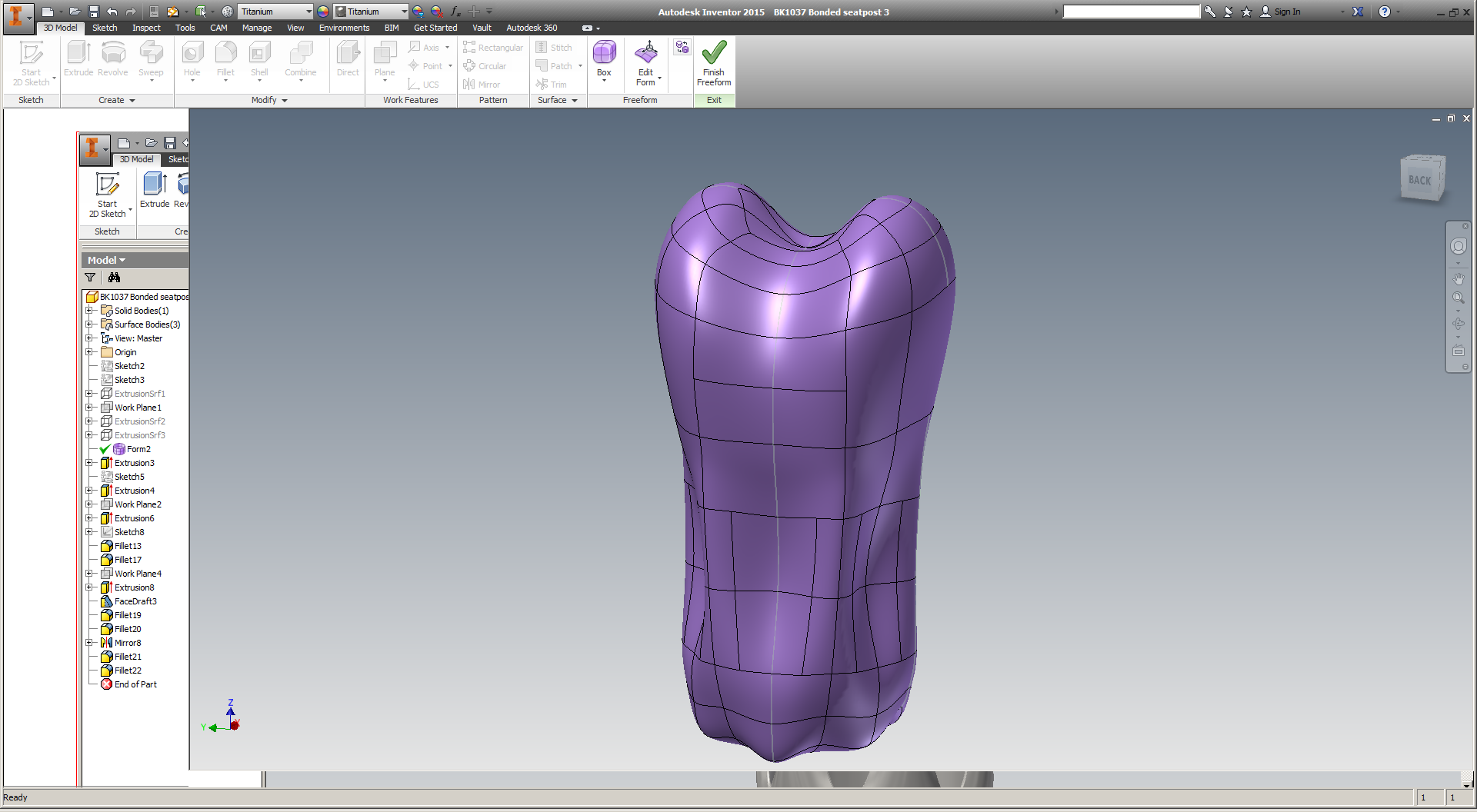

Incidentally, T-splines continue to be *really* weird - and super cool. I really wish I had a more powerful computer; I suspect that would improve the experience significantly.
Last week, while in the Pearl River Delta on a sourcing trip for The Public Radio, Zach and I spent a bunch of time on foot exploring. These are fairly random, and do NOT cover our time spent visiting manufacturers in the area - those will come soon :)
(If you click on a photo and then hover over it, you'll see my notes!)
Thanks *so* much to Dragon Innovation, who helped us plan & manage our trip - and to my friend Dan Hui, who was an excellent tour guide in Hong Kong & point of reference for our whole trip.
After a week traveling in Hong Kong, Shenzhen, and Dongguan for The Public Radio, I wanted to post a few quick thoughts on China and other related stuff. There will be more to come (photos + detailed descriptions of the places we visited), but here are the things that struck me most prominently during the trip.
I feel like if you need reasons to pay attention then you're already lost. Nonetheless:
Thanks *so* much to Dragon Innovation, who helped us plan & manage our trip - and to my friend Dan Hui, who was an excellent tour guide in Hong Kong & point of reference for our whole trip.
Update: This post has received a bit of traffic over the past few days, and I've gotten some nice notes on Twitter as well. I would ask, however, that anyone who's truly interested in the people from Undercurrent (who are now all freshly out of a job) consider reaching out. While my own interest is in advancing industrial additive manufacturing, there are a lot of bright minds (I believe them to be the best in the industry) who are excited to explore and improve the effectiveness and resilience of ambitious organizations. If that's something that excites you, send me a note and I'll connect you with the very best people for the job.
Two and a half years ago, an ad on Radiolab caught my attention. I was listening to a lot of podcasts at the time and paid as much attention to the sponsors as most people do. But this one said something about "3D printing, and the future of human-refrigerator interaction," which was weird. I liked it.
My courtship with Undercurrent was long and slow. I was at a transitional point in my career, and in a lot of ways the skills I had weren't well suited for what UC did. But I stayed in touch, and made friends, and was working on interesting, challenging stuff myself - and being really public about the whole thing. And after a full year on the periphery, I joined Undercurrent full time in April of 2014.
In most respects, the work wasn't what I had expected. I didn't really know what corporate consulting was like to begin with, and Undercurrent's particular take on consulting was an additional degree of separation away from anything I understood.
But it fit, and it fit in a way that I had never experienced before. I made friends. We worked long days at client sites, and wrote long wrap-up documents on the plane back home. We had heated debates on random evenings about the future of 1099 employment law, or whether or not a hot dog could be a sandwich. We hustled; we worked hard. I did some of the most savvy, thoughtful, and critical reasoning of my life. I learned a lot.
A year after I joined, Undercurrent was acquired by Quirky, a startup developing products with the help of an online community. Quirky was one of the bigger New York startup stories for a while, and I had bought a few of their products - and had not enjoyed them. I had thought a lot about product development over the previous few years (and was in the midst of fulfilling my own Kickstarter campaign at the time), and had real doubts about Quirky's take on the subject.
And, so did a lot of other people. Quirky had already had some layoffs before we joined, and there was another round our first week or two that we were in their office. It was a pretty weird place to walk into, though to be honest it really didn't change my work much. We still had our Undercurrent client relationships, and I was too busy shipping radios out on the weekends to think much about how Quirky was doing. But it wasn't going well, and everyone knew it.
In the meantime, my desire to focus on manufacturing was growing. Undercurrent supported this, even giving me a cash budget to spend on titanium 3D printed parts. I was figuring out how to move the industry past the problems I had seen with additive manufacturing. Undercurrent was behind it.
At this point in the story, the details are mostly public. Over the past few weeks, both Quirky and Undercurrent began going through the motions of shutting down, permanently.
I'll miss it. UC valued my work and critical perspective more than anywhere I've ever worked. It offered more in the way of curiosity, and warmth, and just always felt like home.
I'm looking forward to the future. Undercurrent - and the clients we worked with - offered me fantastic opportunities over the past year and a half. But there are other opportunities out there, and I'm excited to find my place working on them.
To my colleagues: Thanks for your support. I wish you the best, and look forward to working with you (it's a small world, after all) in the future.
To my clients: Thanks for your sincerity. I can't think of better people to have worked for, or better problems to have worked together on.
Over the next weeks, I'll be digging deeper into the topics in industrial additive manufacturing that I've spent so much time thinking about recently. If you want to work together, please drop a line :)
Yup.
I was *not* good at this, by the way. The meat was pretty gamey, but actually had good flavor.
The other day I got an email update from Rob Oliver, a machinist in Brooklyn who's helping me post process the EBM printed titanium parts that I got from Addaero recently. There's still a bunch of work to be done, but I wanted to write a bit about how we're thinking of the manufacturing plan - and the constraints that we're facing in the process.
While electron beam melting tends to produce much lower internal stress than laser powder bed fusion does, it's still a decidedly near net shape process. In further iterations I hope to get the as-printed part much closer to the final dimensions, but at this stage the parts I have deviate significantly from the intended tolerances. Specifically, most outer dimensions seem to have grown, most inner dimensions seem to have shrunk, and there are a number of locations where support structures have left unacceptable surface finishes.
My main focus right now is getting both inner diameters to within .006" of their designed size. It's difficult to get a reliable measurement of where they are now (due mostly to surface finish, and the presence of leftover support material), but they both appear to be about .040" undersized. In addition, I suspect that the shorter cylinder is slighly ovalized - though not to the extent that it'll be an issue in the end.
Although there are other conceivable options, the most obvious way to get the IDs within tolerance is milling. By using either a CNC toolpath on an end mill, or a boring bar on a conventional mill, it should be very easy to get well within .006" of nominal dimensions on both areas of the part. However, the issue of fixturing is nontrivial. I designed this part with T-splines, and its outer surfaces aren't orthogonal at all. As a result, we'll need custom tooling to hold the parts in a milling vise.
As an aside: Anyone who says that additive manufacturing eliminates the need for custom tooling has no idea what they're talking about.
In order to securely fixture this part, Rob is machining its negative into a set of aluminum blocks, which can then be clamped securely into a milling machine vise. This technique (which I'll refer to here as "soft jaws," although technically what we're making is more of a coped fixturing block) is used extensively in subtractive manufacturing to hold irregularly shaped parts.
The process of making soft jaws is relatively straightforward, but designing them for this part is somewhat complicated by the dimensional variation that EBM produces. Put simply, feature sizes in EBM parts tend to deviate from the design in the X and Y axes, but stay relatively true to size in the Z. That's because the Z axis is at least partly controlled by the Z stage drive system; the powder bed is lowered a predictable amount with each new layer, keeping features in the Z close to their designed dimensions. But in the X and Y, deviations in feature size are partly driven by the electron beam diameter, and partly driven by the distance that the feature is from the center of the build platform.
As a result, my part has grown anisotropically, and Rob will need (to some extent or another; soft jaws tend to be somewhat forgiving) to compensate for the as-printed dimensions differently in the XY plane than he does in the Z.
In the end, though, the most practical way of determining the final dimensions of the soft jaws is to make a set, test them on the as-printed part, and iterate as necessary. It's conceivable that the first try will work, and it's also possible that if we make the negative a bit too big in all directions, we could use a piece of soft material (for instance, blue tape) to take up the gap.
It's also worth noting that there's an alternative path that I decided *not* to take. A common way to make parts - both with additive manufacturing and conventional - is to design fixturing features into an intermediate stage of the part. These can then be used to hold the part while secondary operations are performed; they can then be removed in a subsequent step. I considered this option, but find it undesirable for the simple reason that it would likely result in more post processing steps. Worse yet, it would probably require the surface of the part to be blended where the fixturing element had been removed, which would be either labor intensive, or unattractive, or both.
Regardless, we should have the first iteration of our soft jaws machined shortly. Expect updates!
Background: My day job is directing Undercurrent's strategy work with General Electric, but on the side I spend my time researching the state of the art in manufacturing - specifically, industrial 3D printing. I've written before about my approach to some of this work, but want to lay out here the way I see it fitting into my career.
As you'll know from my blog (cf. one, two), a primary focus of mine is developing a line of high end metal 3D printed bicycle parts. However, it might not be clear that that's just one step in finding specific applications where 3D printed production parts make commercial sense. In the end, the purpose of my work is to help expedite the transition toward a more fluid, transparent, and efficient mode of product design, manufacturing, and distribution - one which properly accounts for its own externalities, and allows for rapid integration of feedback across and throughout a part's life cycle.
I should be made clear that my long term focus isn't specific to additive. Every manufacturing method has a purpose, and any claim that 3D printing is going to unseat other methods should be examined critically. I want product designers have perfect transparency into how a given process will affect cost and function, and to be able to tune their design such that it's well matched for the resources at their disposal - and the end user's needs.
I do believe, however, that additive manufacturing offers a unique and historical opportunity. Partly because of the fact that 3D printed parts always begin as 3D models - and partly, to be frank, because of its sex appeal - additive has encouraged a new wave of people to people to work in an industry (manufacturing) that was due for a radical change. And while the effect of their naïveté is often to simply create churn, in the end I believe that manufacturing will benefit greatly from the influx of new ideas and working styles.
In order to harness this opportunity, I'm focused on developing the most compelling possible use case for the technologies at play today. For metal 3D printing to reach industrial maturity, designers need to understand its limitations - and how to best exploit its strengths. So I have begun my research with metal powder bed fusion, which is currently the 3D printing process best suited for industrial use. I'm developing parts which make good use of 3D printing's strengths (lightweight, low production volume, smaller than a breadbox), and an industry which prizes the traits that additive manufacturing is best suited for (has short sales cycles, rewards innovative design, benefits from customization).
Today, developing metal 3D printed parts is an expensive process, and it's difficult to estimate how difficult a project will be. So to begin, an easy place for me to provide value has been to explain (in sometimes painstaking detail) the experience I've had over the past year and a half. Because there's so little public information about the realities of metal powder bed fusion, writing on that subject has allowed me to boost my profile quickly.
But more importantly, it has encouraged other people who are working on similar problems to offer collaborations. This has helped me twofold: First, it has in many cases resulted in decreased costs on my end, as the people and companies that I'm collaborating with have given me prototype parts in exchange for me writing long, in-depth descriptions of what they do. But even more significantly, these collaborations have given me unique opportunities to see past the marketing and sales messages and talk directly to the engineers who know the state of metal powder bed fusion best. This has allowed me to advance my own level of knowledge much more quickly than I otherwise could have, and has given me access to people who I can now turn to when I'm stuck.
To be sure, I have a *ton* to learn - and ultimately I'll never know as much as the seasoned professionals who I'm working with now. But between the hands on experience that I'm getting by building bike parts, and the access I now have to the most advanced research organizations in the world, I find myself in an ideal position to identify what aspects of today's manufacturing ecosystem most desperately need fixing - and who the most well positioned players are today. And that, plus the (I hope) sincerity, honesty, and intelligence that I've employed in writing about my own development process, puts me in a position to be a key part of whatever team ends up fixing them.
So, in short, the master plan is:
Don't tell anyone.
ps - Hat tip to Elon Musk, whose strategy (and how he communicates it) rocks.
pps - I also explicitly want to bring more advanced manufacturing development to New York City, which I believe is the best place in the world to do serious work.