Manufacturing guy-at-large.

Filtering by Tag: modeling

Share

Seatpost collar

Added on by Spencer Wright.

After doing even more research on DMLS pricing (update soon), I played around a bit today with designing a seatpost collar. 

BK1026 Barrel nut Seatpost Clamp.jpg

The design here is pretty straightforward. I'm using fairly standard barrel nuts and a M5 bolt (I'll steal these from a Thomson collar I have laying around), and the part profile isn't trying to be innovative either.

I'm getting this printed in alumide (a mixture of nylon and aluminum) for an aesthetic/basic form/function mockup, and will look into pricing on the part too. I suspect that it could be relieved in a bunch of places still (to reduce build time & cost) but for now I don't care too much - I just want to get a functional stainless or titanium part on a bike ASAP.

Updates when Shapeways ships, probably before Valentine's day.

Share

The Lady's Harp

Added on by Spencer Wright.

I've been working with Daniel Fishkin on a electronic sound art project called The Lady's Harp. It's a large scale installation that uses acoustic feedback (from guitar pickups) looped back through contact transducers, which induce vibration on piano strings. Daniel has installed this instrument in a few other settings, but needs it to be easier to set up & tear down, so I'm helping with some basic mechanical design. We're using mostly off-the-shelf components - primarily 8020 extrusion - and a few laser cut acrylic parts.

We're mocking the components up in the next few days, and Daniel will be installing the Lady's Harp in Nothing Space later this month. I'll have more updates soon, but Daniel's description of the project is much more elegant and informative :)

Share

NoHeadSet on Shapeways

Added on by Spencer Wright.

After a couple of revisions, my 3D printed dummy headset is on Shapeways!

It still probably needs a few refinements, but I'm hoping to get a little feedback on it before I make them. I did try it out in my shop recently (NYCVelo also has a prototype), and I can confirm that it looks great and works damn well.

The headset is two parts. The top half has two 3.3mm holes "drilled" in it; they need to be tapped M4 in order to make the assembly really work well. I would recommend using brass tipped set screws for aluminum or steel steerers, and nylon tipped set screws for carbon fiber. You can also experiment with thumb screws or plain old socket cap screws if you like.

This may seem like an obscure part, but for anyone who has spent any time handling bike frames & forks, it'll come in *really* handy. If that sounds like you, grab one on Shapeways and let me know how it works!

Share

Short!

Added on by Spencer Wright.

The Public Radio is now shorter :)

We've been working on fitting everything into the next size down jar for a little while, and this afternoon we made a few steps in that direction. To celebrate, I spent a few hours modeling the target jar. 

The previous model was one of my first surface models, and I hacked it together *hard.* In the meantime I've gotten a lot more experience with NURBS, and it was great banging this out quickly. It's a lot more realistic in many ways, though I did half-ass the Ball logo a bit.

On the electronics front, Zach cranked out a new board design and we should be ordering a new PCB tomorrow. I also ordered new lids (one based on the new design, which is heading in the direction of sheet metal stamping). Meanwhile we've got a breadboarded version running, though it's a bit unwieldy. 

Expect more in the next week.

Share

Public Radio Progress

Added on by Spencer Wright.

More on the electronics side soon (we had some good progress today), but for now just a few images.

I spent a bit of time today remodeling the lid to account for a few slight changes. The real rationale has to do with the potentiometer, which needed to be reoriented slightly. In the meantime I laid the speaker holes out a bit differently, and I'm pleased with the result.

I hope to have the whole thing together & in a jar by the middle of this coming week - finally! 

Share

Saddle

Added on by Spencer Wright.

Quick afternoon project: make a quick saddle, plop it on the topper model. 

My workflow for the saddle: Started as a quadball T-spline body in Fusion 360. Played with it for maybe a half hour, then converted to a BRep and exported as a STEP file. Imported that into Inventor. Made two 2D sketches for the rail sweeps, then did a 3D intersection curve on them and swept a 7mm rail profile along the resulting path (I'm still using standard saddle rails here, I know...).

The workflow isn't that bad, and the whole process didn't take more than an hour and a half... but if I had a 3D scanner I probably would have used it, at least just to get the saddle top shape. 

Incidentally, I spent a little while looking around the fi'zi:k site (I fucking hate the punctuation in their name), and came across their new Volta saddle. I like the look of it, and would have copied it if I had seen it a little earlier.

Ultimately I'd like to get rid of the rails on the whole assembly and mount the saddle top directly to a redesigned topper. Stay tuned.

Share

Public Radio hardware

Added on by Spencer Wright.

For a variety of reasons, the Public Radio was due for a complete hardware redesign (the potentiometer wasn't fitting, and so a smaller speaker was required... etc.). I got that mostly done this afternoon - modeled the new speaker and a knob, and redesigned the lid to fit them.

I'm not totally sure how I feel about the grille design, and if I had to bet I'd say it'll change soon. I'm also curious whether we can fit everything in the next size smaller jar, which is the same footprint but half the volume and *really* cute. Previously, we chose this jar so that a deeper speaker could be used, but the one we're planning for now is tiny - despite its good power output.

I'm hoping to get this new lid printed and delivered next week, which is about when the electronics should be coming together. Stay tuned.

Share

Yeah.

Added on by Spencer Wright.

It's subtle if you haven't been looking at this the past few weeks, but this model has seen a bunch of improvement in the past two days. These interior surfaces, and the variable fillets connecting them, are pretty cool.

Share

Also

Added on by Spencer Wright.

Variable fillets are cool.

It's a little hard to tell, but I'm filleting an edge on the interior of the part here. Because of the particular geometry, I really want the fillet to be big in the middle and small on the sides, so I define multiple points on the edge and tell Inventor to blend fillet radii along the edge.

It's worth noting that all of this is some decidedly 21st century shit. Which I think is cool.

Share

Less sketches, etc.

Added on by Spencer Wright.

TOPPER PROGRESS UPDATE! Prettier, lighter, stronger.

I ended up rebuilding this model completely today. This is 100% NURBS surfaces, and is about 80% of what I want it to be... which is just about right, considering where the product is at, lifecycle wise.

In all of the mini-galleries below, the new part is shown in blue-silver; the old model is gold. 

The most noticeable change is in the bottom/rear of the lofted middle portion. I added a few rails to guide the outer surface, and worked to blend the loft more with the clamp body - and the barrel.

The front of the part looks pretty similar, but the bulge in the back is now gone, and a number of the transitional surfaces are more fully blended.

I also optimized the window shape a bit in order to reduce stress in the corners. 

But the bigger changes are on the interior surfaces. There, I created fully tapered faces, which distribute material just where it's needed. The resulting structure is lighter and less prone to failure. It's a bit hard to see, but the new part has an arc-shaped inner wall on the top right, and the bottom left wall of the lofted transitional portion has a completely different - and much improved, I think - shape.

You'll also notice that I removed the little ledge around the perimeter of the inner diameter of the part. It was originally intended to be a hard stop for the seatmast to bottom out on, but I was able to eliminate it - while retaining the core function - but moving the window's bottom edge to the same plane. 

The result is much more organic, and distributes strain more evenly around the part. I'm not totally done fine-tuning it, but the initial FEA results are promising.

As you can see, the corners of the lower section are stronger now, and strain there is more evenly distributed. And because of the way I rebuilt the model, it shouldn't be too hard to beef up the necessary portions a bit.

Although I'd like to take another shot at some of the loft geometry, I've been thinking ahead a little too. I suspect that the clamp portion can be relieved a bit, and have been playing with some shapes... I rather like the result :)

Share

Too Many Sketches

Added on by Spencer Wright.

I've been working on optimizing the Topper a bit, which has involved starting from scratch and remodeling the loft a little smarter. 

...But it's getting complicated. There's *way* too much here, and this is a stripped down version of what I had last night. 

Basically, NURBS surfaces kinda suck - building this loft is a PITA. I would try this in Fusion 360 with T-splines... but I'm hesitant. Last week's version was pretty close to where I wanted it, and I thought that I could rebuild it quickly and move on. My work this morning will tell whether I was wrong.

Share

Stress

Added on by Spencer Wright.

This is modified a bit from last night. Fillets, window dimensions, and a few wall thicknesses are revised. Overall effect is that it's lighter and stronger. 

Simulation-animation-safety-factor.gif

Still more work to go, but it's getting there :) 

Oh - and this simulation is 2000 Newtons - about 450 pounds-force.

Share

Topper taking shape

Added on by Spencer Wright.

Made a bunch of changes to the seatmast topper last night.

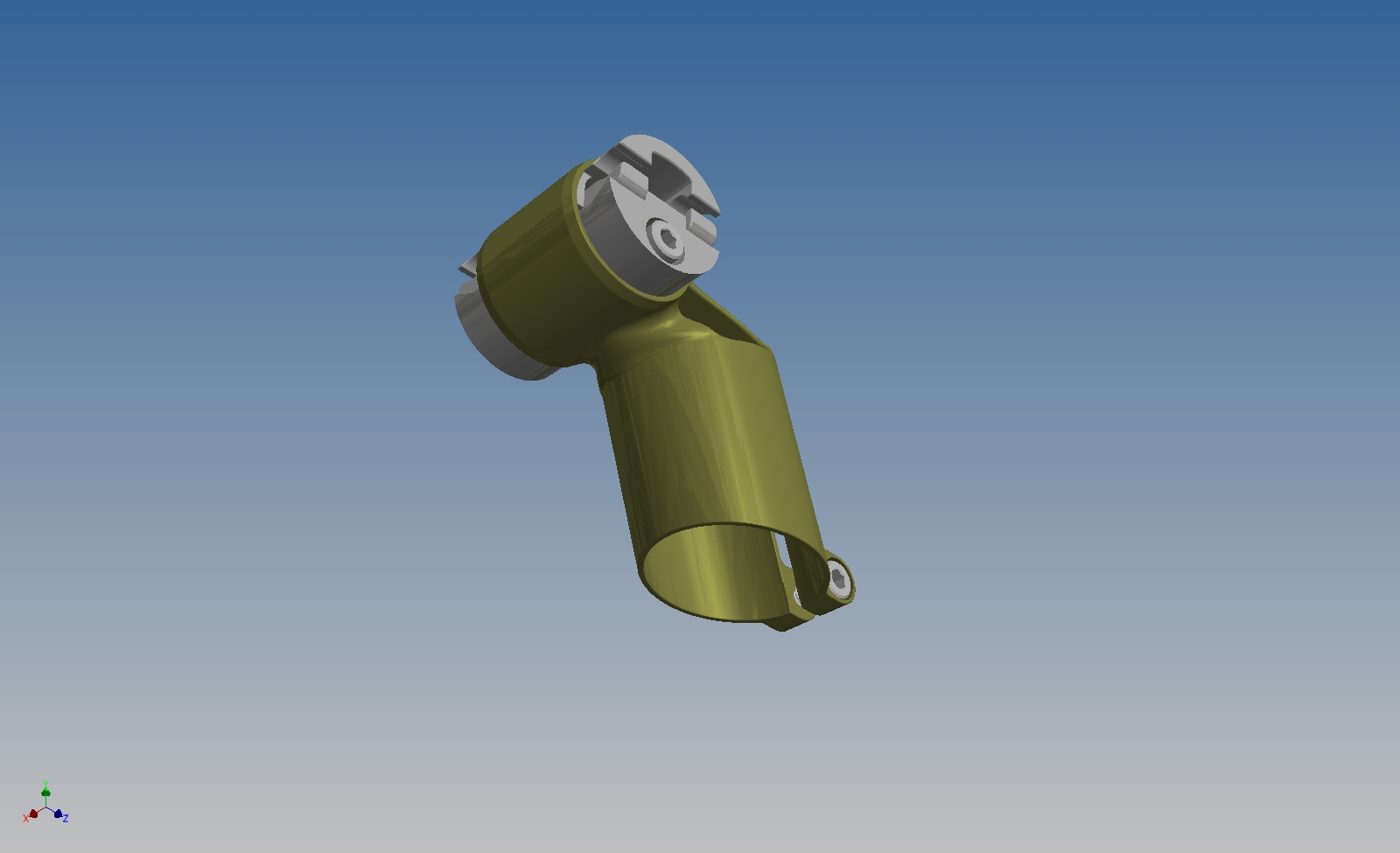
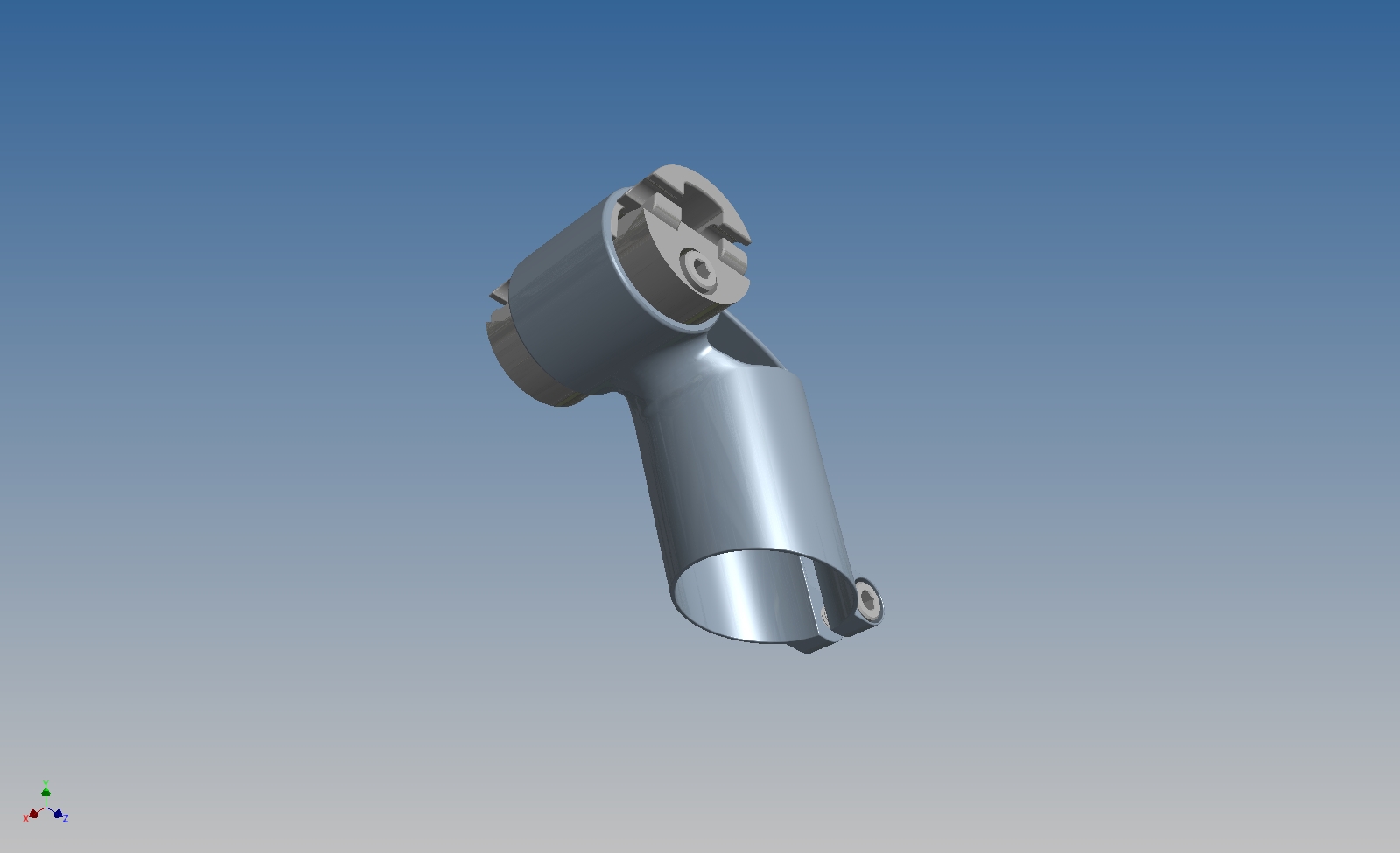
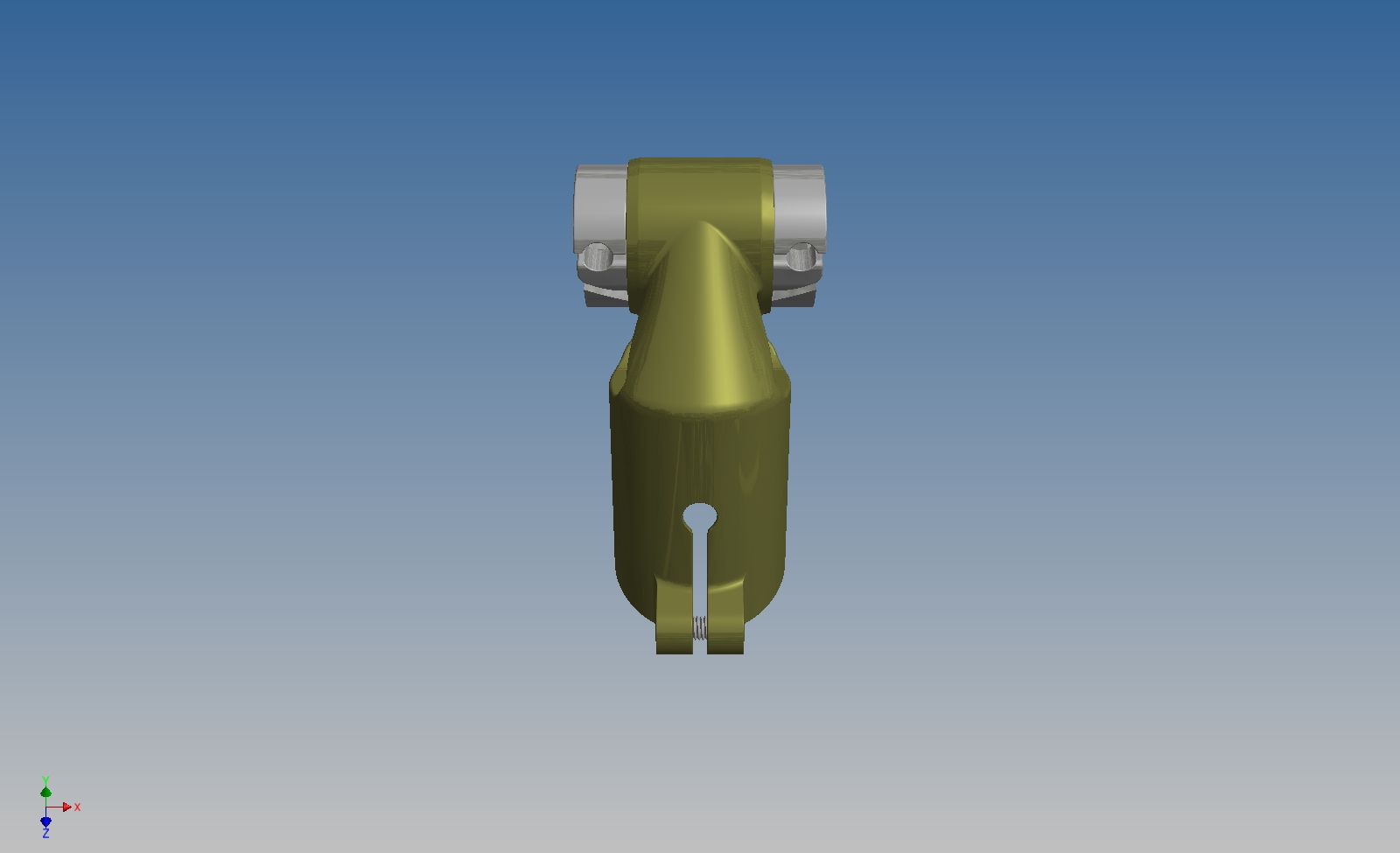
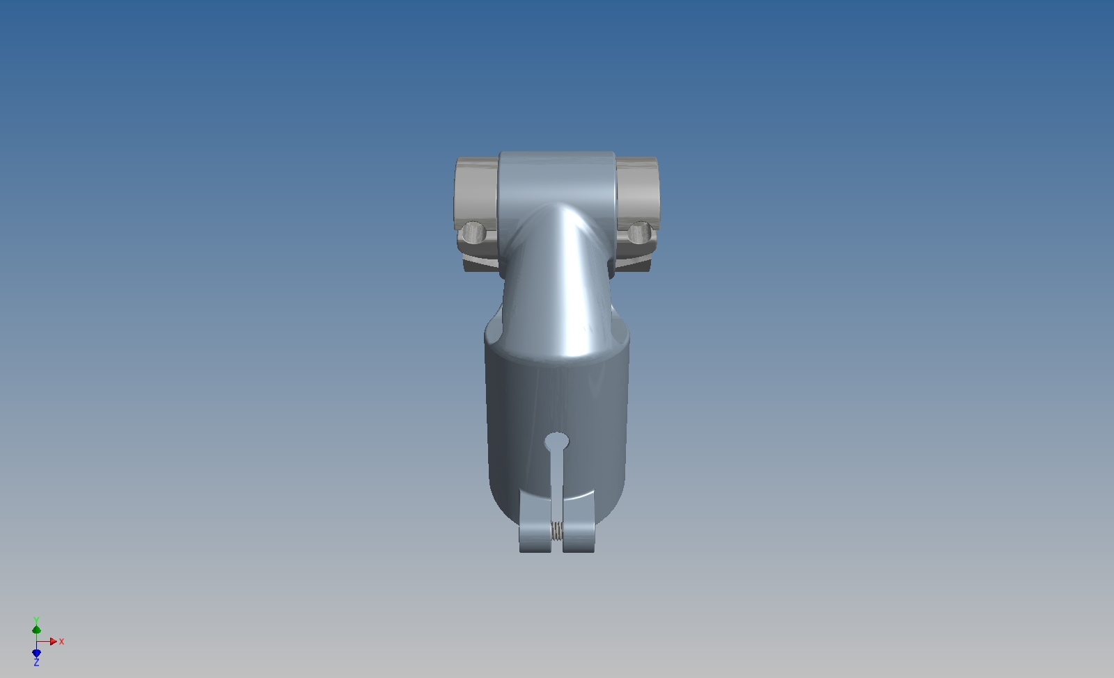
I ended up rebuilding the entire lofted body, which is basically the whole middle section of the part. Doing so allowed me to modify it down the line, which is really useful when building NURBS surfaces. After making the outside shape, I ended up needing to tweak it a lot to avoid collisions with later features. Accommodating these changes is hard to do, though - you kind of need to know what the part is going to look like before you start. It's a real chicken-and-egg problem. What usually ends up happening is that you don't do it right until you've rebuilt the whole model three or four times, which is about where I'm at here :)

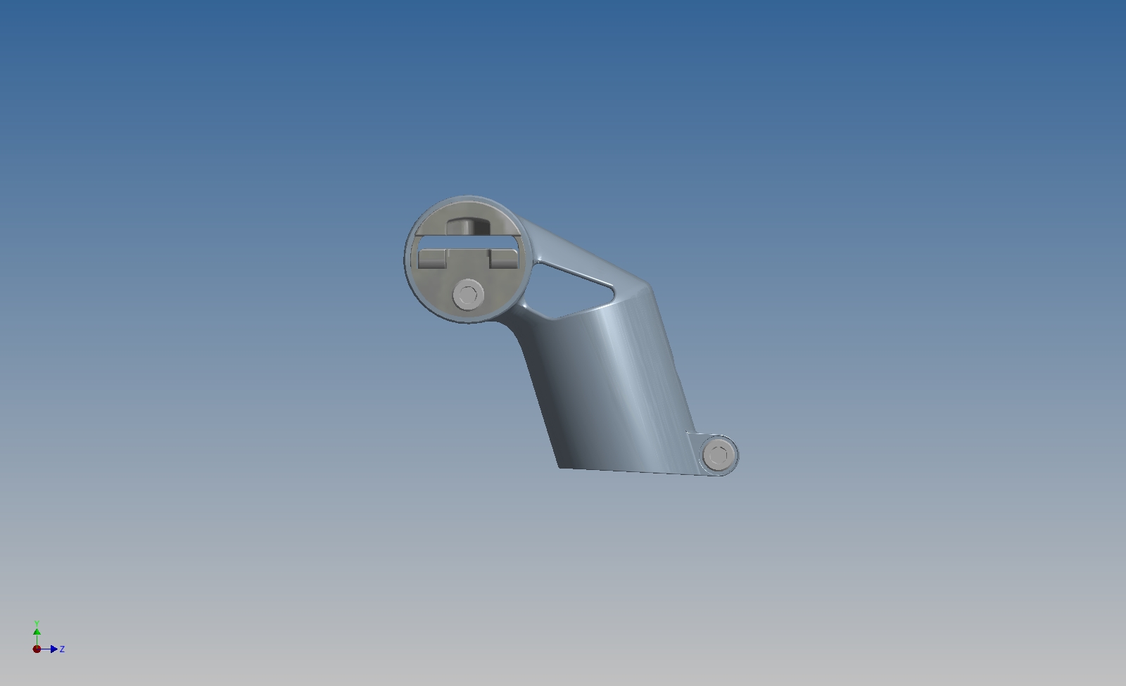
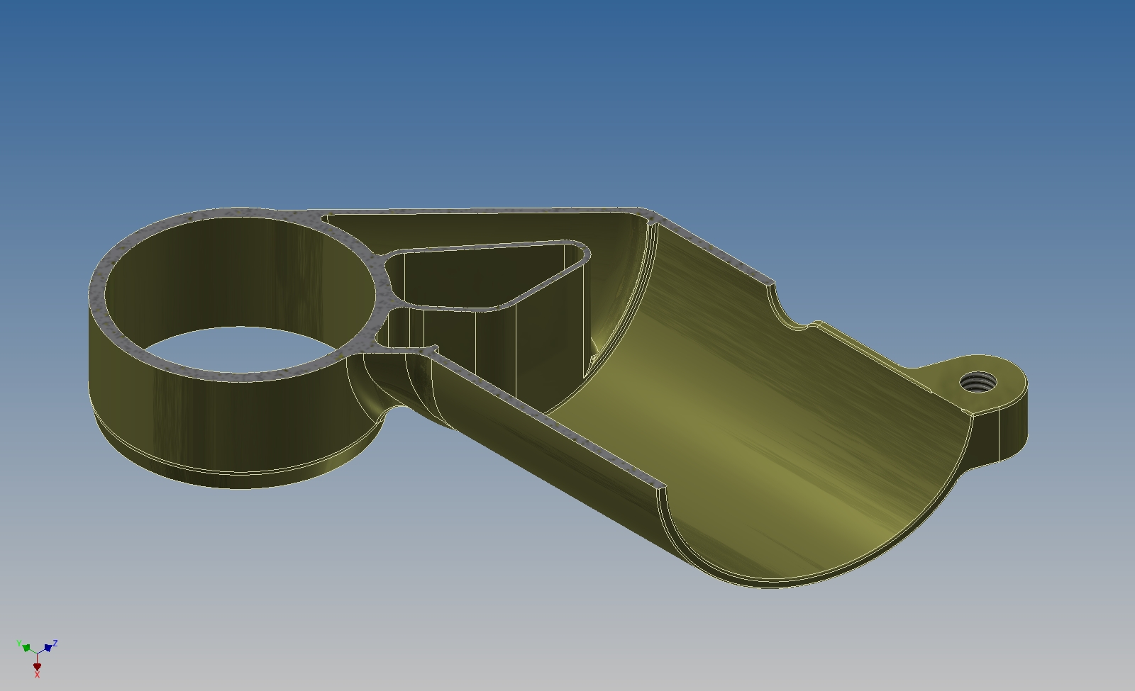
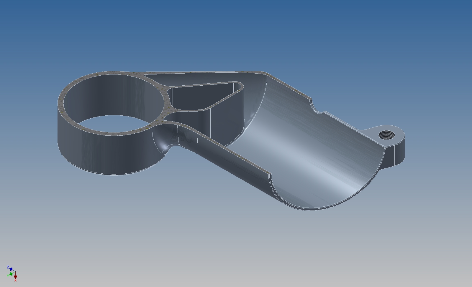
It's hard to describe, but the upper section is hollow. I also spent a while trying to optimize around shared surfaces, so the window upper & lower walls coincide with features that I already needed on the part. The one thing I'm not particularly happy about is the seatmast clamp at the bottom of the part. The details are a little different, but overall it's designed the same way it would be if the part was welded. This part is going to be 3D printed, though, and I'd prefer to find a way to build the feature in a way that directly addresses its manufacturing method.

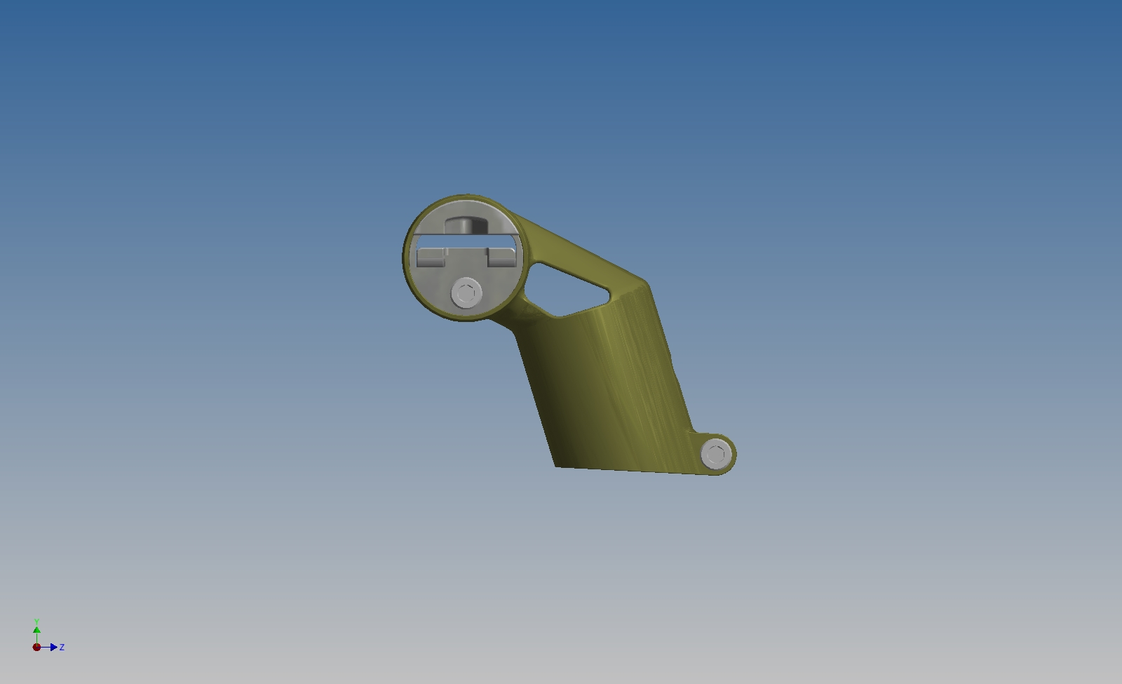
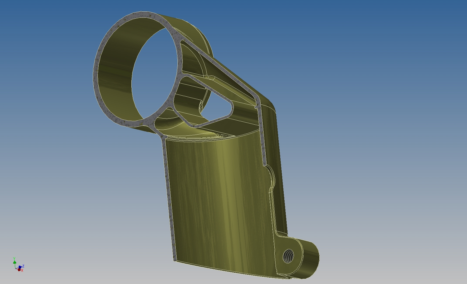
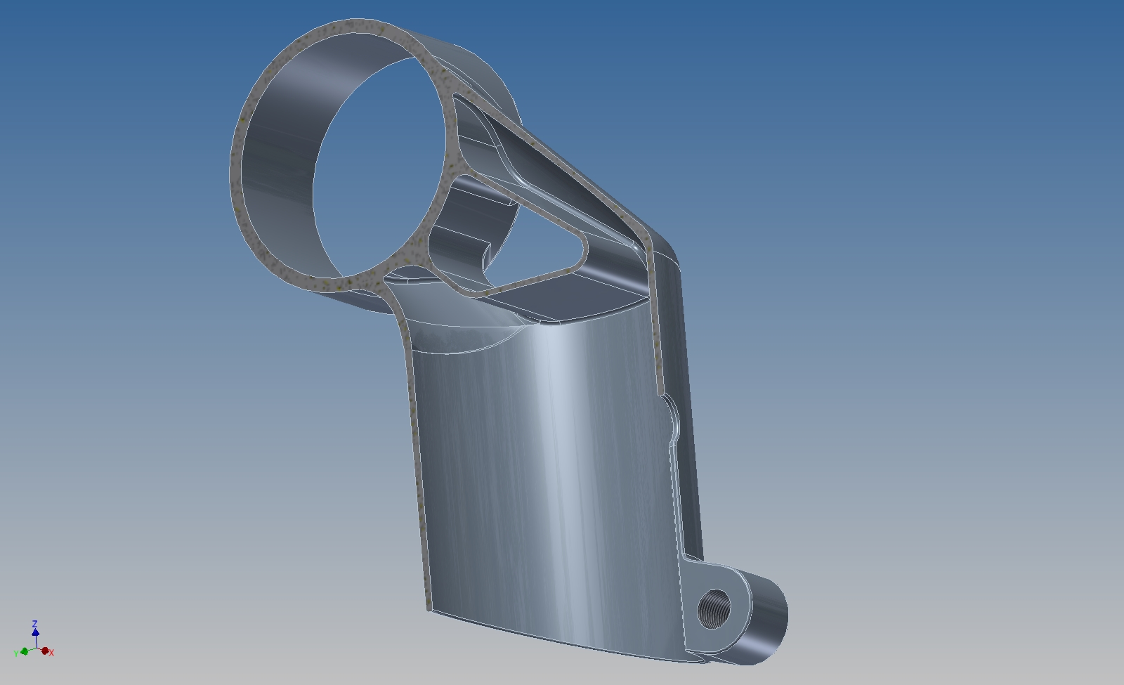
But overall, the part is definitely forward looking. I'll post a section view later, but for now just take my word that most of the middle of the part would be impossible to make by any other method than additive manufacturing. Also, right now the topper body (just the gold part, not including hardware) comes in at 74g, and I suspect that with a little work I can shave that even more :)

Share

More T-Splines

Added on by Spencer Wright.

This is pretty fun. The first shot is of the control frame view; the second is smoothed - which is how the part would be produced. 

I'm new at T-spline modeling, and have a few issues with this model. Nonetheless, it's basically ready to be converted into a mechanical assembly. There, it would be split into a frame and arms; hinges would be installed; lens features would be designed. 

Pretty fun.

Share

T-Spline modeling

Added on by Spencer Wright.

This model took me about 45 minutes. It's basically the first "organic" model I've ever created. 100% T-spline geometry, all on a piece of free software. 

I started with a single torus on the XY plane for one of the eyepieces. I applied a "Mirror-Duplicate" on the YZ plane, creating a second eyepiece that automatically mirrors whatever I did on the first. Then I created the only sketch in the entire model - a basic nose bridge, spanning from eyepiece to eyepiece. I created a "Bridge" feature between the two eyepieces, then began to sculpt. A bit into the process, I created the temples by extruding them from the faces closest to the top corners of the eyepieces.

At this point, I could export STLs and have this printed as a full scale, physical, part-in-hand mockup. The entire process - from sketching the torus to completing the print - would take about 4.5 hours. 

Note: I'm assuming you're using FDM (a process I'll begrudgingly accept for quick mockup purposes), e.g. MakerBot, and that your Lean, One-Piece-Flow Supply chain (as it were) is ready and running smoothly.

Share

Pretty lucky

Added on by Spencer Wright.

This is kinda obscure, but I've spent the past few days learning all the ways that you *can't* get vector text into Autodesk Fusion 360. Fusion doesn't support text input directly, so I've been creating vector text in Illustrator and then exporting/importing. That's all fine, but there are also some issues in Fusion with importing SVGs... it's a bit unclear. Anyway I'm getting closer:

I was shocked to learn that keeping all the original text vectors in there (as opposed to just exporting the stroke outline) ended up being the key. It was a PITA to extrude just what I wanted, but in the end it worked.

This T-spline model was extruded and then "patched"... Results were mixed. 

Share

Can

Added on by Spencer Wright.

So, 3dfile.io supports Autodesk Inventor *and* Solidworks files right out of the box. Sketchfab, on the other hand, only does these dumb tessellated formats that all the 3D printing people use.  

Note that the body appearances in this viewer actually aren't what I have them as in Inventor; apparently 3dfile.io is applying some sort of changes to the file when I upload it. Regardless, not having to export as a different file format is great. I don't see how I'll be using Sketchfab at all anymore.

Oh. Also, I modeled a can. Pretty neat, huh?

Share

Topper

Added on by Spencer Wright.

Recently.  

The number and complexity of the surfaces here is just dumb, and it's my fault. I ended up rebuilding it with a solid model, though I'd like to revisit the surface model again.