Playing with a seatpost. This design needs lattices (or topology optimization).
Manufacturing guy-at-large.
Filtering by Tag: A7
Island scanning, and the effects of SLM scanning strategies
From a (highly academic) paper titled "The influence of the laser scan strategy on grain structure and cracking behaviour in SLM powder-bed fabricated nickel superalloy" (emphasis mine):
Changing the scan strategy however, or indeed investigating the effect of a different scan strategy, should be approached with caution as the geometry of the component or sample being produced may have a serious influence; the data presented in this study relates to a simple cuboid. Consider a sample with a large cross-section; the time between each laser pass will be much greater than that of the sample seen here conversely for a thin section the time between each laser pass may be significantly reduced and a band heating effect (similar to that seen with the ‘island’ scan-strategy) may be observed. More complex still would be a geometry transitioning between a thick and thin section or visa-versa. Therefore by applying a single laser scanning strategy for the entire geometry, the actual structure of the material may not be the same as that predicted from simple cuboidal trials.
Ideally the optimum scan strategy would be calculated on a layer by layer approach taking into account the part geometry and even adjusting the fundamental parameters of laser power and scan speed allowing the microstructure to be tailored to the final application of the component; this would require significant research into the thermal modelling of the SLM process.
Currently however this is not possible and so the ‘retro-fix’ solution of utilising a post-fabrication HIP treatment has been shown to be effective at closing the internal cracks within the material.
Some background: the DMLS and SLM processes use a focused laser beam to selectively melt (or sinter; the distinction can be hazy) powdered metal into a solid part, cross-sectional layer by cross-sectional layer. Since the beam can't melt an entire cross-section all at the same moment, it instead traces back and forth across the part, melting a single line at a time until the entire cross section is done. This gif, from the Solid Concepts blog, gives a good sense of the process:

Once a layer is complete, another 20-40 micron layer of metal powder is laid out, and the laser scanning process starts again.

The SLM/DMLS (and SLS, for that matter) build process.
You might not stop to consider it, but the pattern that the laser takes as it traverses the part can have a huge effect on its structural properties. As the paper at hand discusses at length, one strategy is to break thick cross-sectional areas into a grid pattern, and scan adjacent grid zones in opposing directions. This method is called "island scanning."
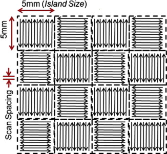
Much like a brickwork bond pattern, the 5mm x 5mm grid is shifted 1mm for each successive layer in both the X and Y dimensions. Interestingly, the crystalline structure of the resulting part varies as you look across the island boundaries. As a result, if you look at a SLM part under a scanning electron microscope, you observe distinct 1mm x 1mm crystalline grids:
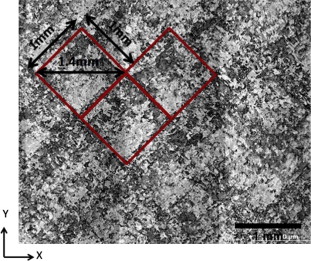
In addition, micro-cracking and porosity (which is generally quite low; these parts are commonly around 99.7% dense) follow the same pattern. These effects can be mitigated - indeed, nearly eliminated - by hot isostatic pressing (HIP), and most SLM and DMLS parts are HIP treated by default.
The interesting question for me, though, is how these factors apply to thin-walled parts. My seatmast topper's wall thicknesses are in the neighborhood of 1mm, and thinner in areas. As the authors of this paper note, cracks that are open to the surface of the material aren't always closed by HIP. My suspicion is that the feature sizes at issue here are orders of magnitude smaller than they'd need to be to have a noticeable effect during the lifetime of the part, but only destructive testing (or a better trained material scientist than myself) will bear that out.
I'm also not sure, to be clear, how these crystalline structures compare to those of samples produced via conventional (i.e. non additive) methods. If anyone knows of a good study on the micro-structure of drawn titanium tubing, I'd love to see it!
Hardware user testing
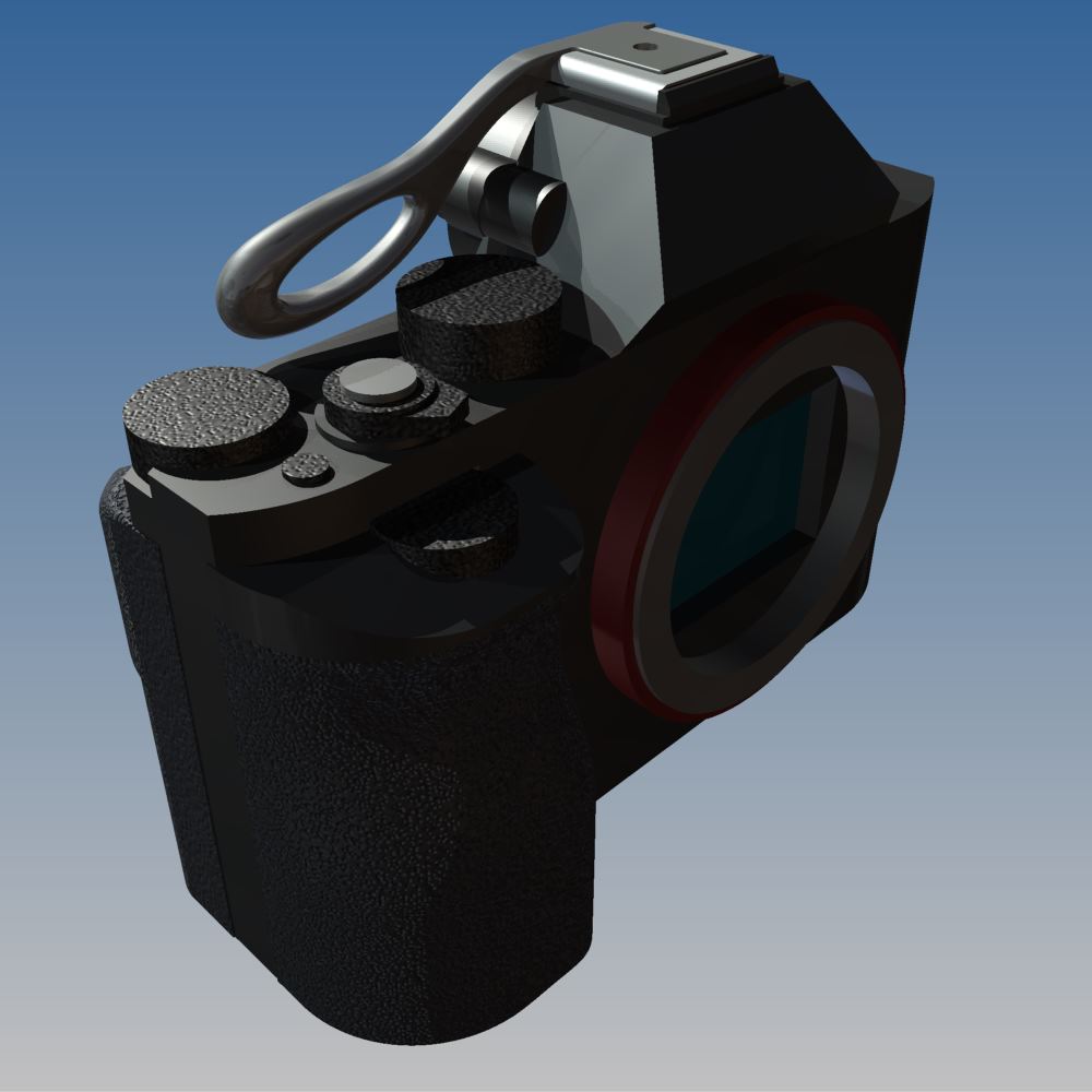
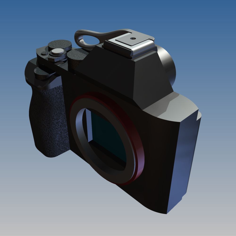
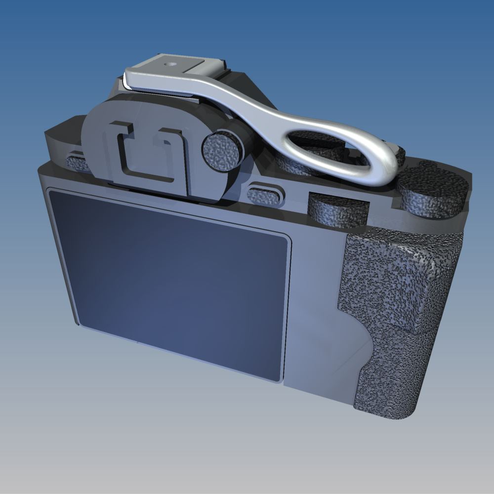
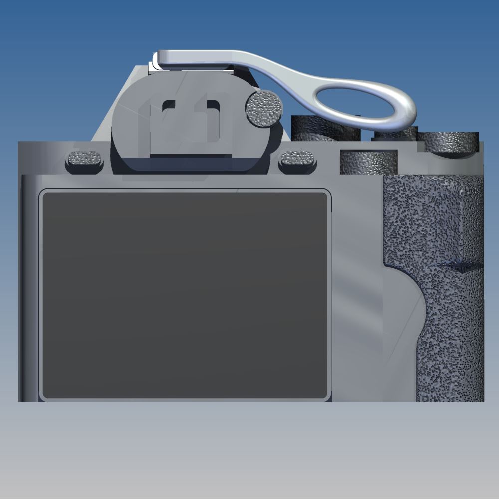
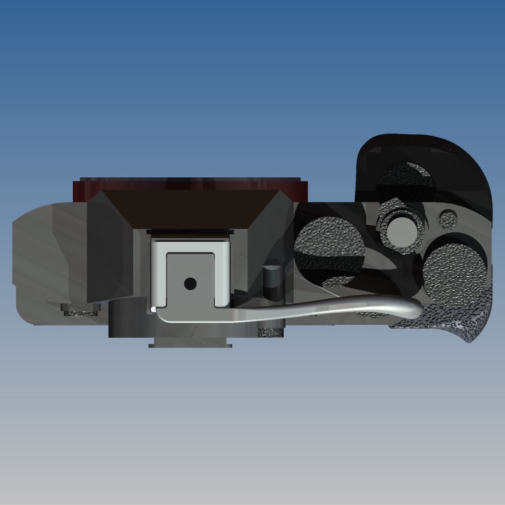
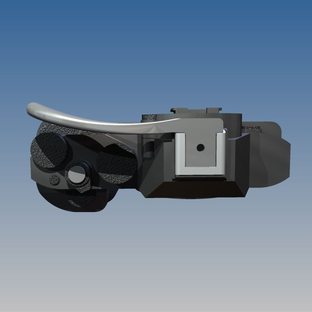
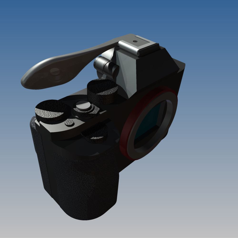
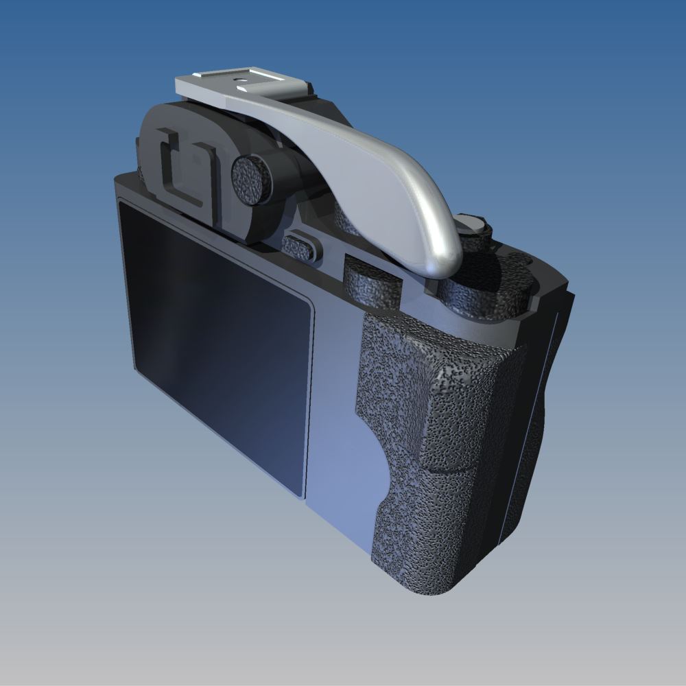
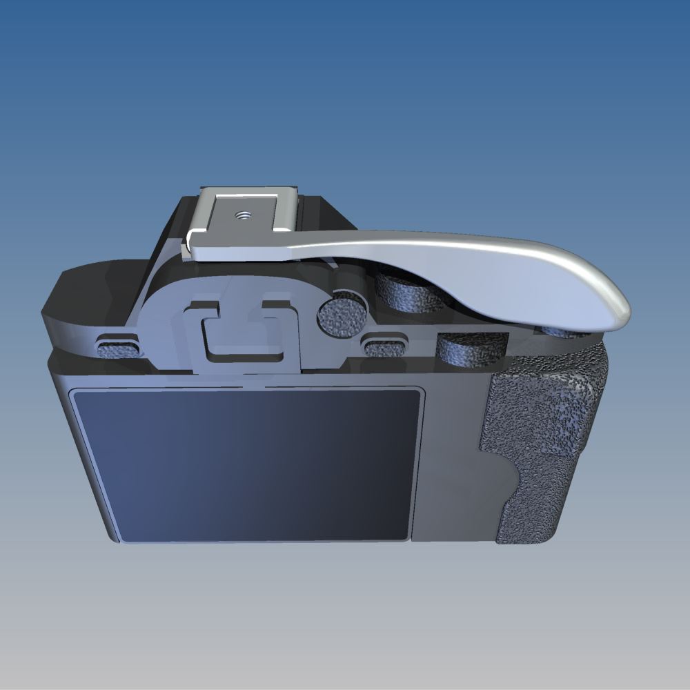
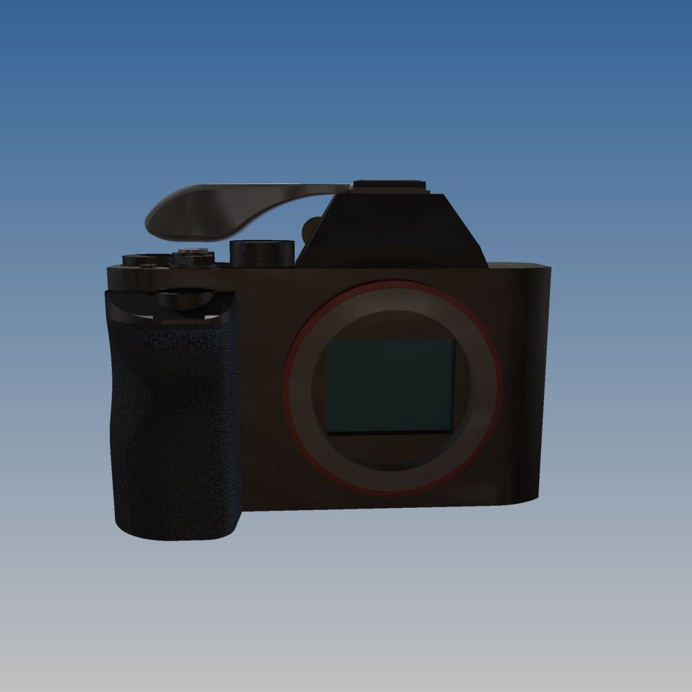
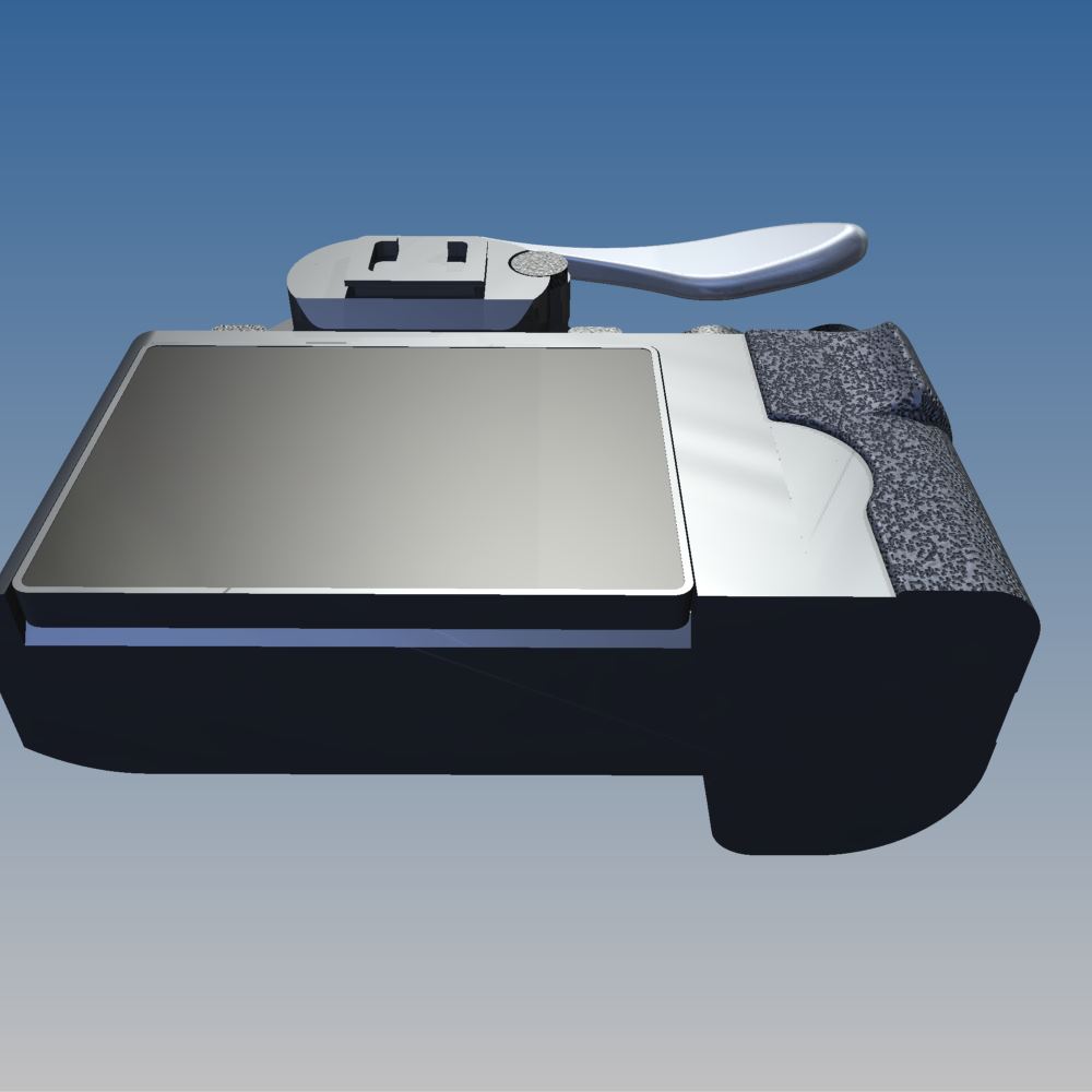
Kane & my Sony A7 thumbrest finally got tested the other day:
The verdict: it needs to be shifted back somewhat, so that your thumb can reach it a bit easier.
Iteration to come!
Wohlers 2014
The Wohlers Report - the leading authority on 3D printing - is out, and my seatmast topper is in it!
Pick yours up while they're hot - if you can swing the sticker price, it's an excellent resource on where advanced manufacturing is headed.
Thumbrest
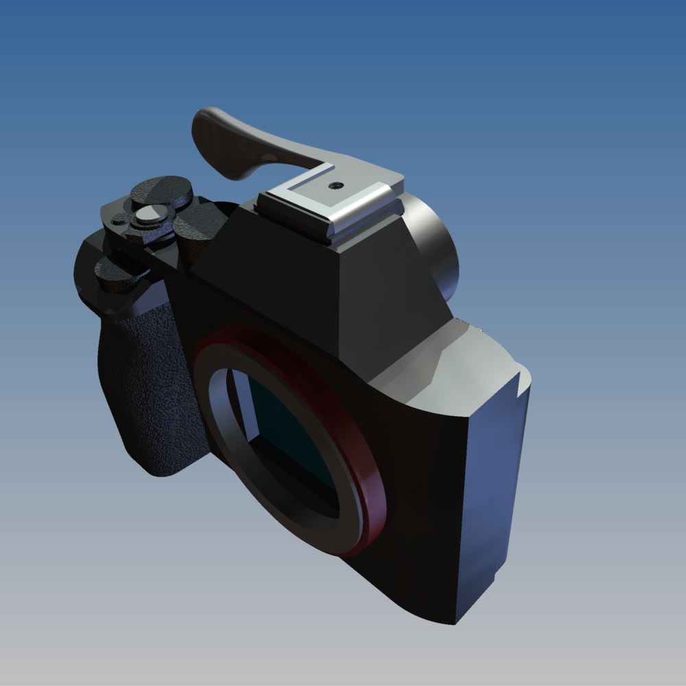
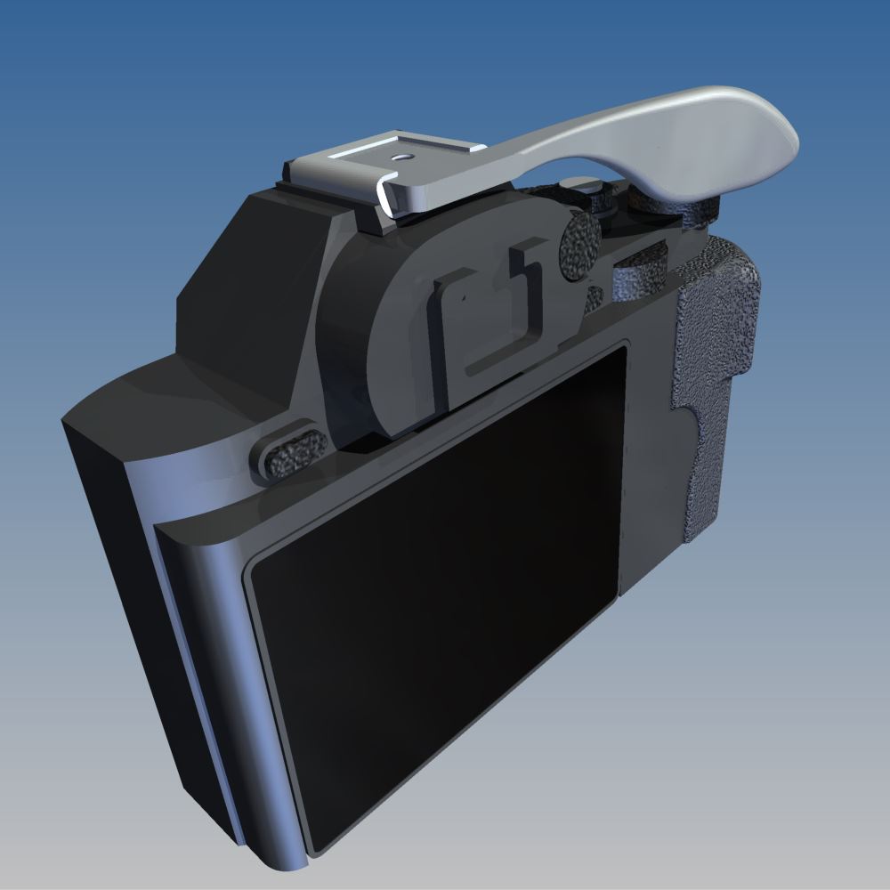
Got this back from Shapeways a week or so ago.
To recap, this is designed to be installed in the hotshoe of a Sony A7, in order to improve the grip stability & feel.
I still need to do some post-processing & try the part out. I'm excited to put it together.
Iterating
Rebuilt most of this A7 thumbgrip model today.
Incidentally, Shapeways is complaining about the wall thicknesses on the hotshoe insert and a small area on the top of the cutout. I suspect this won't be much of an issue, but it could be.

Camera

DMLS Site Visits
Last week, I had the pleasure of visiting two excellent resources in the world of additive manufacturing. What follows is all in relation to my titanium 3D printed bike seatmast topper project.
Within Lab
On Wednesday I sat down in the Brooklyn Navy Yard with Kaveh and Siavash of Within Lab. Within's software takes solid models as input and allows the engineer to convert them to 3D lattice structures in order to reduce mass and build time - and maintain structural integrity. Their software is no joke; it's clear that for engineered mechanical products, Within Enhance is going to be key to making 3D printing a viable manufacturing method.
There were a few key takeaways:
- The base portion of my topper is a thin walled sleeve. I suspect it could be latticed (instead of having a consistent wall), but I don't believe Within's software will generate curved lattice segments. The demos they ran all assumed a thin skin on the ID of the cylinder, but I suspect there's a better way - which would likely require a curved lattice.
- It's possible that many of the theoretical benefits of Within's process will be somewhat tempered by the nature of my relationship (as a designer) with the job shops that will eventually produce the parts. Optimally, the job shop has an intimate understanding of the design intent of the part - both its function *and* the assumed build characteristics. In other words, I would hate to optimize my part for a vertical build orientation, and then find later that my supplier was building horizontally. Big things like that should be easy to avoid, but it'll require a bunch of management and communication on my part.
- I'm unsure whether Within Enhance will be able to find an elegant design for the pinch bolt on the front of the Topper. I'd prefer to eliminate the bolt altogether, but I'm trying to redesign as little of the wheel as possible here. This isn't a criticism of the software itself - just an anomaly of my particular design (and the design of bike parts in general).
- Within's software deals entirely with STLs, which are limited in their portability. I don't think this will be a serious issue, but I was a bit surprised about it.
It's also worth noting that I really need to redesign the saddle clamp if I'm going to take full advantage of the manufacturing process. Again, though, I'll probably hold off for now and just focus on getting one of these made - and on a bike - ASAP.
Incodema
On Thursday, I got a facility tour of Incodema (warning: autoplaying audio on their site!), a job shop in Ithaca NY with DMLS, CNC, stamping, wire EDM, and welding capabilities. I also got a chance to talk in depth with Scott about their DMLS capabilities and the idiosyncrasies of my project.

Some of the parts that Incodema commonly makes.
A few interesting things that I learned here:
- Incodema uses wire EDM extensively for post processing. I had just assumed that part cleanup was either manual or machining, but EDM makes a lot more sense for lots of parts. Incodema keeps a bank of EDM machines, as uses them both for DMLS cleanup and for toolmaking for their stamping shop.
- Incodema is developing a proprietary surface finishing treatment for DMLS parts. I'm aware that this is a hot topic (another supplier bragged of their ultra secretive process), and grumblings continue in the traditional manufacturing world re: DMLS's low (Ra ~400) surface finish. It's unclear where Incodema is with their process, but the first articles I saw were quite pretty.
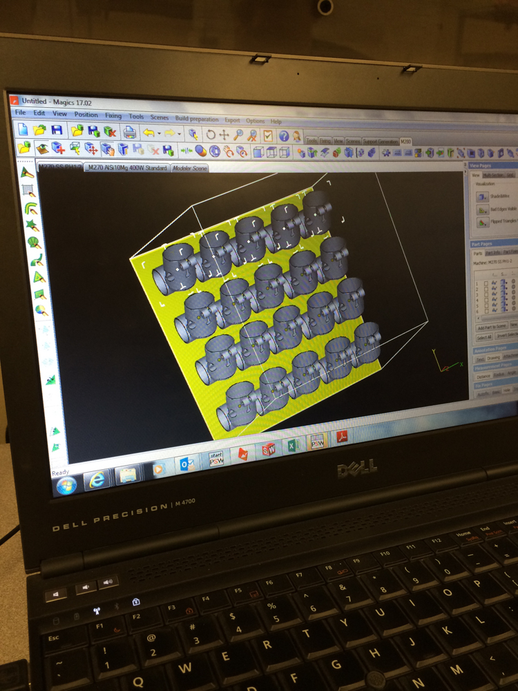
- After hearing Within's off-the-cuff recommendations about build orientation, Scott and I spent a little while setting up a build platform and support structures for my part. It appears that we could build 20 parts per build with the part oriented roughly upside-down, and we were able to reduce support structures a bit too. We did, however, increase build height significantly, and it's unclear what effect that'll have on the per-part price. (I should have more info on this soon.)
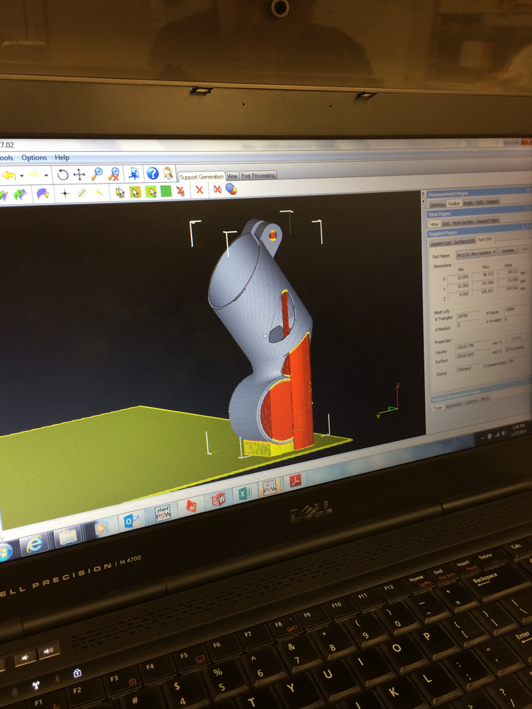
I also got a chance to see a bunch of other DMLS parts in their shop. Most were NDA and couldn't be photographed, but this demo knife blade was pretty cool :)
It's a little hard to see, but almost everything on the top left side of this image is support structures (the part is built with the blade edge up), which can be snapped off manually. Support structures on parts like this are built with perforations in a couple different dimensions, including along the part edge, so removal isn't too hard. The resulting blank still needs to be post processed pretty heavily, though - this knife will require polishing, probably some tapping, and the blade will need to be sharpened as well. My part had an estimated 1 hour of post processing, which seems really reasonable to me.
Next Up
I need to spend some time reconfiguring my design. It's likely that I strip away a few more features, and possibly redesign the bolt boss as well. I then need to think a bit on how I can prep for support structures, and whether I can remove areas of the part (especially around the saddle clamp tube) in order to reduce build time and mass. It's possible that I'll reduce the offset of the topper as well, as it both increases mass and also requires a lot more support in order to build the part.
I'll be putting a bit more time into this project over the coming week; expect updates.
Test Protocols
From EN 14766:2005: Mountain Bicycles - Safety requirements and test methods, published by the European Committee for Standardization. Reference courtesy Marcus Schroeder (of EFBe, a bicycle testing firm in Germany) via LinkedIn.
The tests described here are roughly what my Topper would need to pass. (I've excerpted here for clarity.)
Note that 4.14.4 applies only to the saddle itself, so the current design wouldn't need to go through that step... but I've got schemes which might change that.
4.14.4 Saddle/seat pillar - security test
4.14.4.1.2 Test Method
With the saddle and seat-pillar correctly assembled to the bicycle frame, and the clamps tightened to the torque recommended by the bicycle manufacturer, apply a force of 650N vertically downwards at a point 25mm from either the front or the rear of the saddle, whichever produces the greater torque on the saddle-clamp. Remove this force and apply a lateral force of 250N horizontally at a point 25mm from either the front or rear of the saddle, whichever produces the greater torque on the clamp (see Figure 48).
4.14.5 Saddle - static strength test
4.14.5.2 Test method
With the saddle clamped to a suitable fixture representation of a seat-pillar and the clamps tightened to the torque recommended by the bicycle manufacturer, apply forces of 400N in turn under the rear and nose of the saddle cover, as shown in Figure 49, ensuring that the force is not applied to any part of the chassis of the saddle.
4.14.6 Saddle and seat-pillar clamp - fatigue test
4.14.6.3 Test method
Insert the seat-pillar to its minimum insertion depth in a rigid mount representative of that on the bicycle and with its axis at 73* to the horizontal. Mount the saddle on the seat-pillar, adjust the saddle to have its upper surface in a horizontal plane and to be at its maximum rearward position in the clamp, and tighten the clamp to the torque recommended by the bicycle manufacturer. Apply a repeated, vertically-downward force of 1000N for 200,000 cycles, in the position shown in Figure 50 by means of a suitable pad to prevent localised damage of the saddle cover.
The test frequency shall not exceed 4Hz.
My current feelings on topper
What follows is cross-posted from a discussion on linkedin re: my DMLS seatmast topper. Some of this is specific to a comment I received there, which basically boiled down to "the pricing structure and logistical/engineering benefits of DMLS are poorly suited for bike parts generally, and seatmast toppers specifically."
I've done a bit of pricing research and the numbers aren't totally crazy. Sure, the current cost is 2-3x what I'd want it to be, but between redesigning the part, and buying by the build platform (6-10 parts per order), and improvements in the technology (especially multi-laser machines), I'm actually not too far from other ultra-high-end seatposts. Consider that ax-Lightness sells their 2200 post for €467 - over $600. Even without significant drops in DMLS pricing, I can already buy my design at under $500 (at quantities of 6), with almost no overhead or fixed costs, no tooling to amortize, etc... It seems to me that there's an opportunity there somewhere, but I'm probably something else?
I completely agree that seatmast toppers aren't necessarily the best application of the technology - and moreover, my design is a pretty inefficient geometry to boot. I'm totally open to suggestions on this front - I'd love to test pricing on low mass/volume, high value consumer parts that aren't bicycle related!
That's really the key for me: To produce consumer products via DMLS. I tend to think that it's an inevitability, given improvements in the technology and a bit of intelligent planning & design. It's totally possible that I'm wrong about that, though - and like I say, it's not as if my planning & design is fully fleshed out either :)
I'd love to hear more of your thoughts, either here or via email (snwright@gmail). Thanks for the feedback!
Spencer Wright
Teardown
After doing a bunch of price research on my Topper, I'm embarking on a near full-scale teardown. The reason is, as I noted earlier this week, that I'm not really taking advantage of the technology as much as I could be. My design requires a lot of support structures, and could also be a bit less massive.
As a result, I'm pursuing a different approach. Early this week I spoke to Sia Mahdavi at Within Labs, and I'm hoping that his company will be able to guide me through this next step - converting what is essentially a hollow tube-like structure into a lattice form.
My first step was to strip my model back down to a primitive shape, which I did this evening.
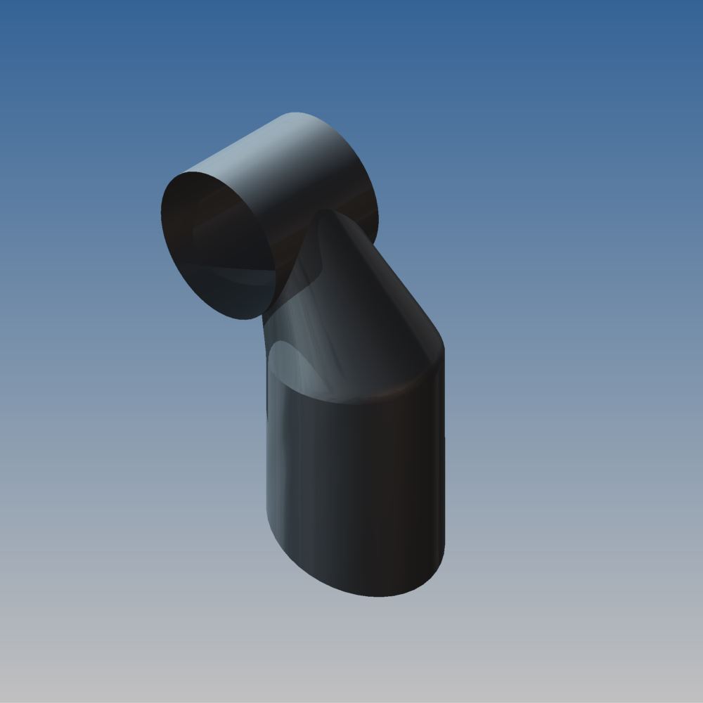
By removing a lot of the features I had in the model, I can give Sia and his engineers a clean starting point from which to reimagine the design. Ultimately I may end up reconfiguring the part more significantly (the saddle clamp mechanism is, in some ways, sub optimal) but for now I'm just excited to see what they come up with. Expect updates next week.
MFG RFQ View rates
For traditionally manufactured parts, MFG has a large enough supplier network that you almost always get a handful of good quotes. My rack end, for instance, went out to over a thousand suppliers. About 75 viewed the RFQ, and to date I've received 7 bids. Another dozen or so suppliers are apparently "preparing quotes."
When you shrink the pool down, though, the rates matter a lot more. There are a *lot* of swiss turning shops in the US, but very few that can produce DMLS titanium parts. So when I posted my seatmast topper, I tracked the results with a lot more interest.
The RFQ went out to 110 suppliers. 8 viewed it, and I have yet to receive a single quote.

Incidentally, there is at least one supplier on this list who did *not* view the RFQ but whom I found separately via Google.
The thing that really strikes me here is MFG's total incapacity to move my project forward - quotes or not. In optimal situations, MFG is an effective marketplace to compare quotes for manufactured parts. What it's not good at, however, is the broader function of connecting designers with manufacturers. Anything I want to learn about the DMLS process - information that inevitably is going to come directly from the engineers and operations managers that are quoting and building my parts - is totally missing from the MFG experience. Instead, I'm left to do leather-to-the-ground work the same way I always have: an afternoon spent with Google + a phone line.
There's definitely a place in the world for a manufacturing marketplace, but I'm pretty sure this could be better.
Regardless, I'm beginning to develop a few old-fashioned leads on good DMLS job shops, and I hope to have some real - and reasonable - pricing in the next few days.
File conversion woes
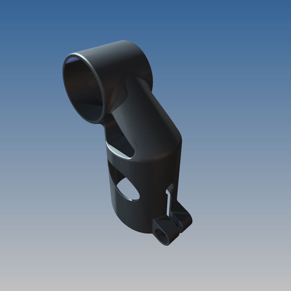
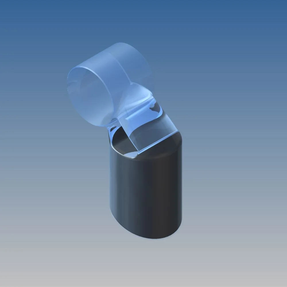
This is why dimensioned PDF drawings are so extensively used in procurement. The top photo is from a supplier from MFG.com; the bottom one is the STEP that I originally uploaded to MFG.


This supplier has obviously downloaded my STEP and performed some translation or conversion on it, and in the process has deleted a few faces (you can see the difference in the foreground of the part, and in the areas he's highlighted in red). This is clearly an inexperienced supplier, and one that I would ultimately have a *really* hard time choosing. I'm not sure what he did or how he did it, but the fact that he made this mistake is an indicator that we'd have issues down the road.
(To his credit: the photo came from a message he wrote me saying that he "noticed some missing surfaces on the part file," and asking me to fix them. So he knew that there was a problem, but didn't understand what it was and wasn't able to troubleshoot it himself.)
In traditional manufacturing, 3D part files are created and edited in a program like Inventor or SolidWorks. The parts are then brought into a separate environment in the same application and drawn and annotated in multiple 2D views on a "paperspace." The resulting drawing file (.IDW for Inventor) is a dynamic representation of the original part; if you modify the part file, the drawing will update automatically.
You *never* submit drawing files directly to a manufacturer. Instead, you export PDFs of the dimensioned drawings, and *optionally* include STEP files (which are essentially cross-platform 3D files) as a courtesy. The STEPs can be used to help the manufacturer set up their CNC machines, but they're for reference only; the PDFs (with all their dimensions and annotations) are what you're buying.
"Organic" shapes - like those that 3D printing is so well equipped to make - don't fit into this process well. Complex surfaces are *really* difficult to define clearly and completely in two dimensions, and so most 3D printed parts are built from solid files. In this case I submitted a STEP, which manufacturers will convert to an STL and then run through a slicer and feed into their machines.
The problem is that STEP files aren't immutable, and the supplier in this case has apparently deleted a feature from the part. In this case the result was obvious, but there are a lot of features that he could modify or delete that would be a lot more difficult for him to detect, and my QC job would be accordingly tricky.
This process should be better. The PDF workflow is inconvenient, but at least it's an effective barrier to issues like this one.
Also, we need more, and more *good*, DMLS suppliers.
Saddle
Quick afternoon project: make a quick saddle, plop it on the topper model.
My workflow for the saddle: Started as a quadball T-spline body in Fusion 360. Played with it for maybe a half hour, then converted to a BRep and exported as a STEP file. Imported that into Inventor. Made two 2D sketches for the rail sweeps, then did a 3D intersection curve on them and swept a 7mm rail profile along the resulting path (I'm still using standard saddle rails here, I know...).
The workflow isn't that bad, and the whole process didn't take more than an hour and a half... but if I had a 3D scanner I probably would have used it, at least just to get the saddle top shape.
Incidentally, I spent a little while looking around the fi'zi:k site (I fucking hate the punctuation in their name), and came across their new Volta saddle. I like the look of it, and would have copied it if I had seen it a little earlier.
Ultimately I'd like to get rid of the rails on the whole assembly and mount the saddle top directly to a redesigned topper. Stay tuned.
Yeah.
It's subtle if you haven't been looking at this the past few weeks, but this model has seen a bunch of improvement in the past two days. These interior surfaces, and the variable fillets connecting them, are pretty cool.
Also
Variable fillets are cool.
It's a little hard to tell, but I'm filleting an edge on the interior of the part here. Because of the particular geometry, I really want the fillet to be big in the middle and small on the sides, so I define multiple points on the edge and tell Inventor to blend fillet radii along the edge.
It's worth noting that all of this is some decidedly 21st century shit. Which I think is cool.
Less sketches, etc.
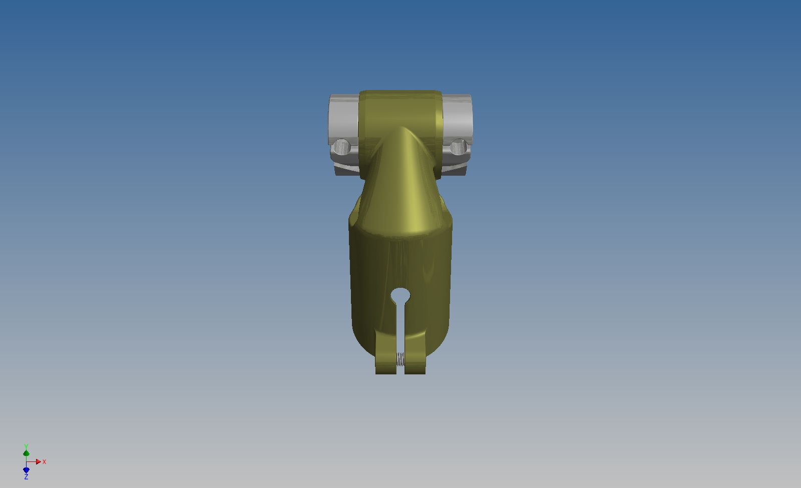
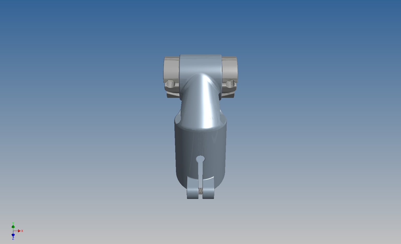
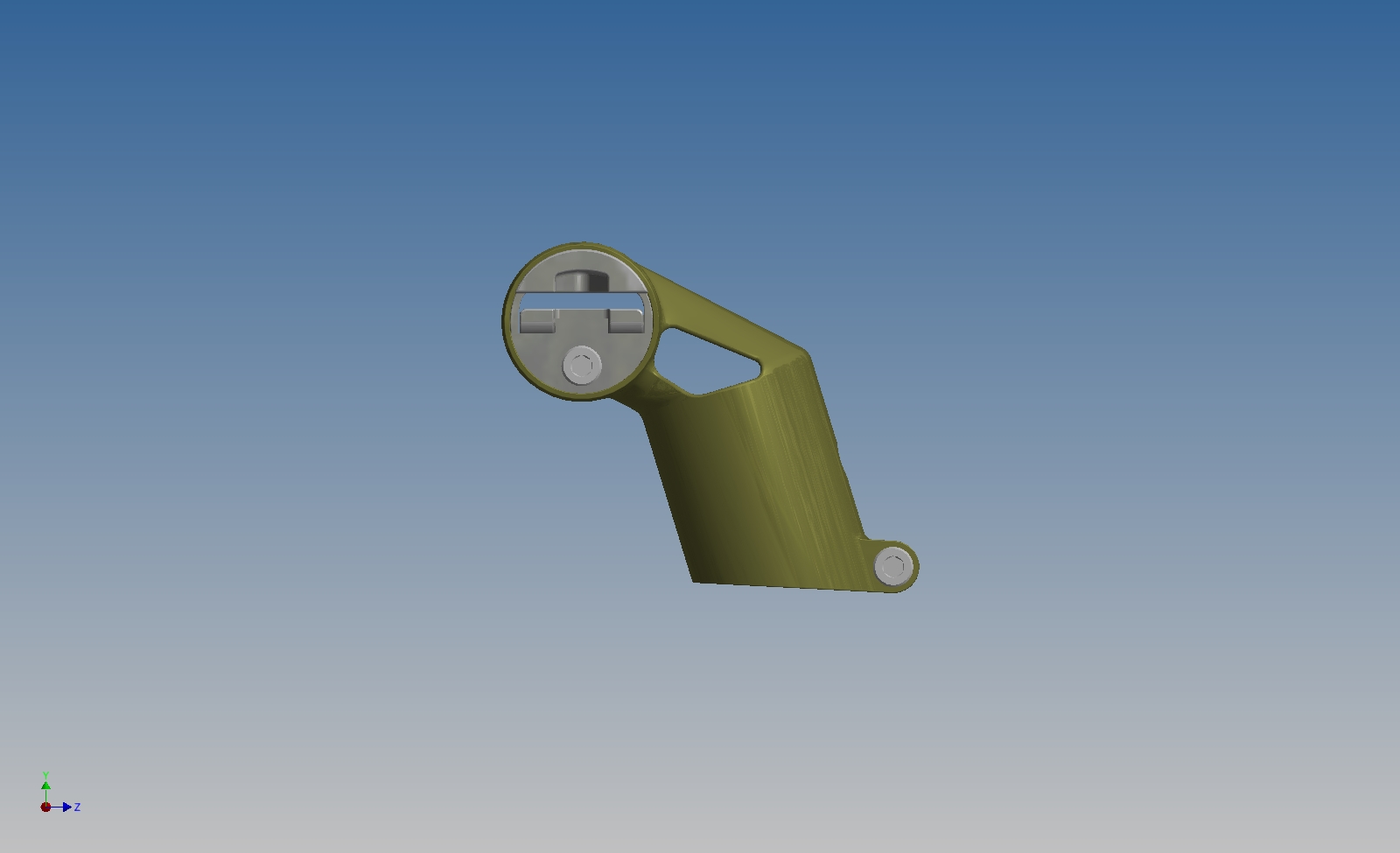
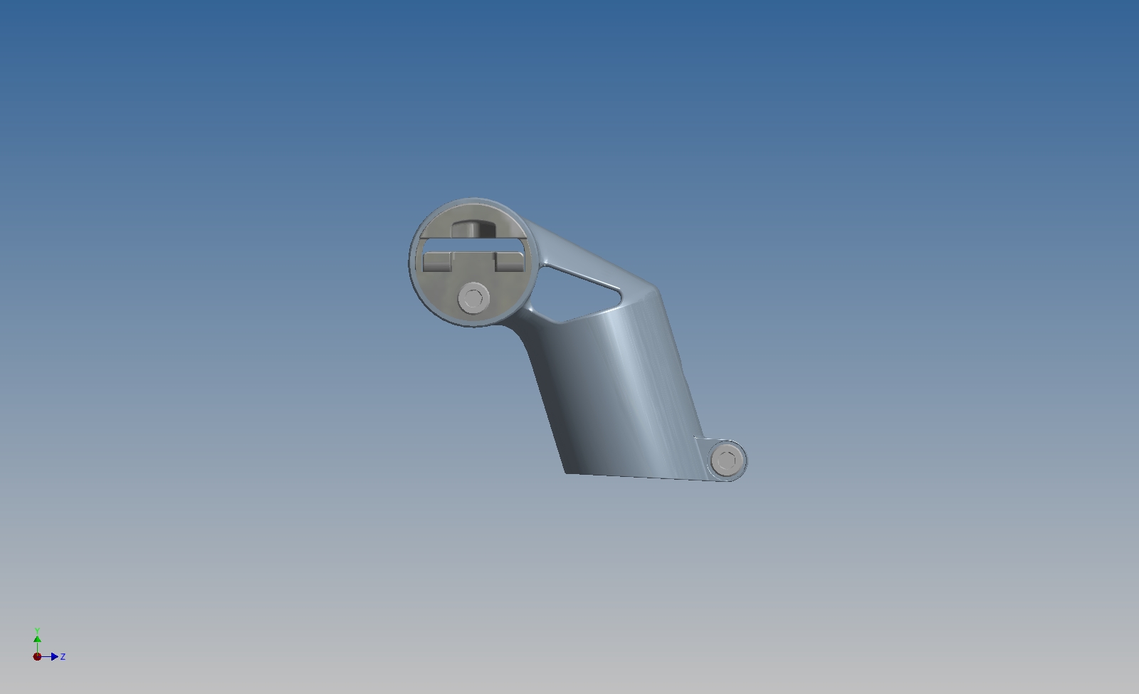
TOPPER PROGRESS UPDATE! Prettier, lighter, stronger.
I ended up rebuilding this model completely today. This is 100% NURBS surfaces, and is about 80% of what I want it to be... which is just about right, considering where the product is at, lifecycle wise.
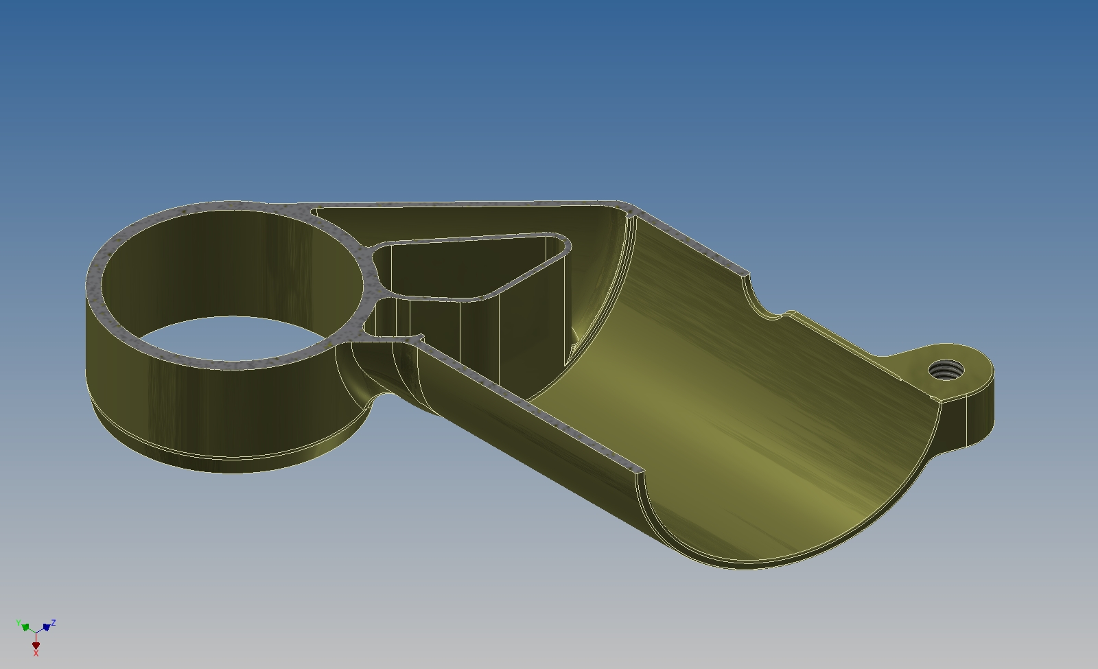
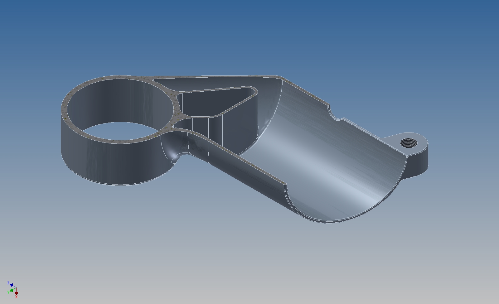
In all of the mini-galleries below, the new part is shown in blue-silver; the old model is gold.
The most noticeable change is in the bottom/rear of the lofted middle portion. I added a few rails to guide the outer surface, and worked to blend the loft more with the clamp body - and the barrel.
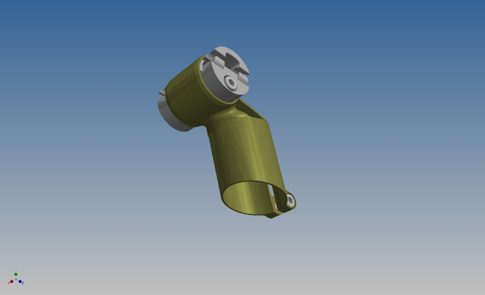
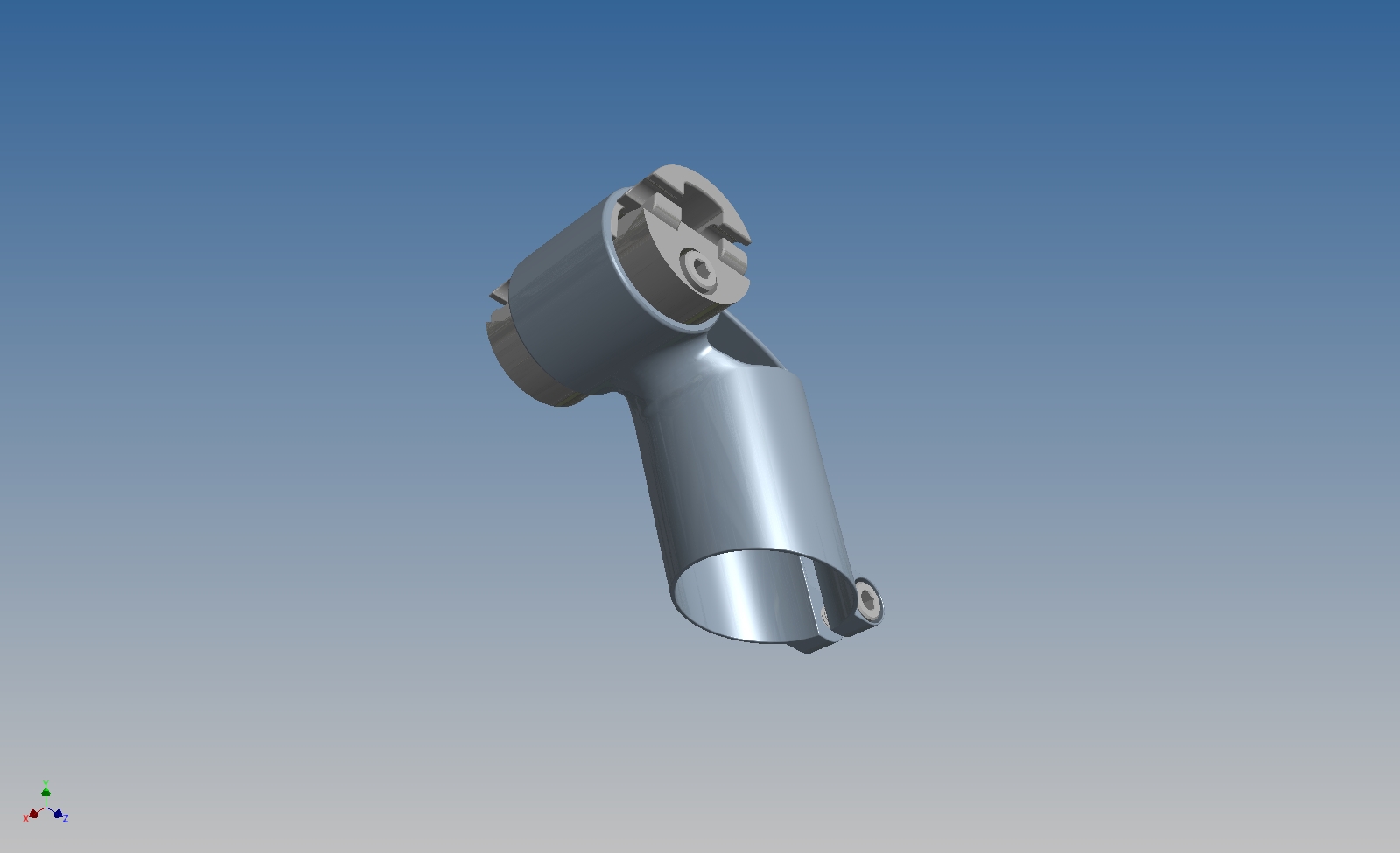
The front of the part looks pretty similar, but the bulge in the back is now gone, and a number of the transitional surfaces are more fully blended.
I also optimized the window shape a bit in order to reduce stress in the corners.
But the bigger changes are on the interior surfaces. There, I created fully tapered faces, which distribute material just where it's needed. The resulting structure is lighter and less prone to failure. It's a bit hard to see, but the new part has an arc-shaped inner wall on the top right, and the bottom left wall of the lofted transitional portion has a completely different - and much improved, I think - shape.
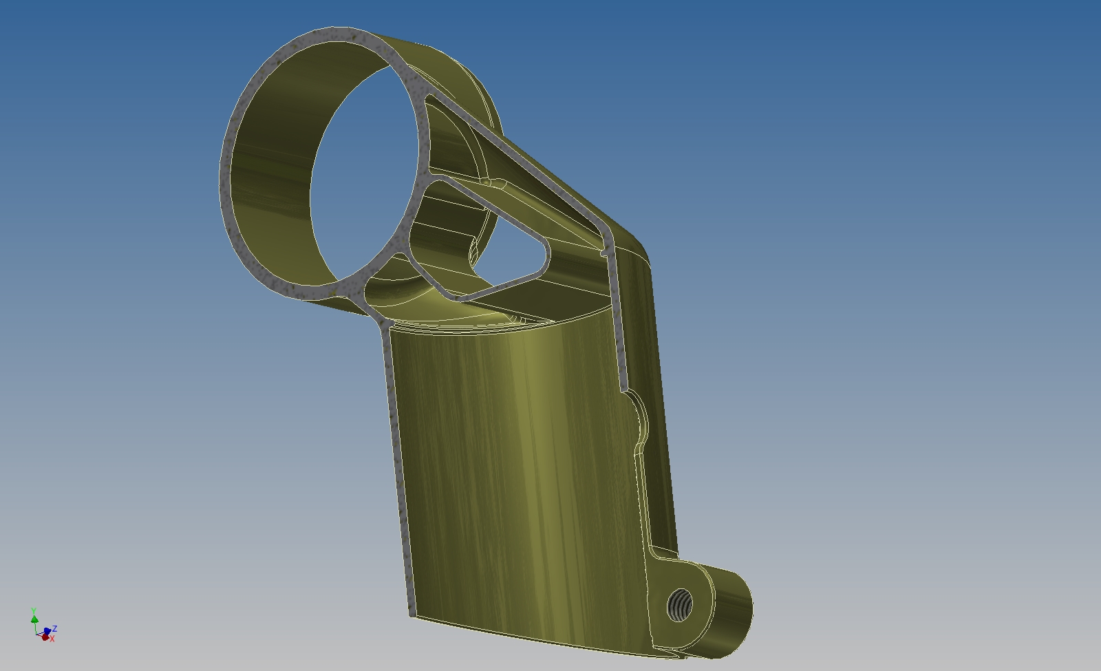
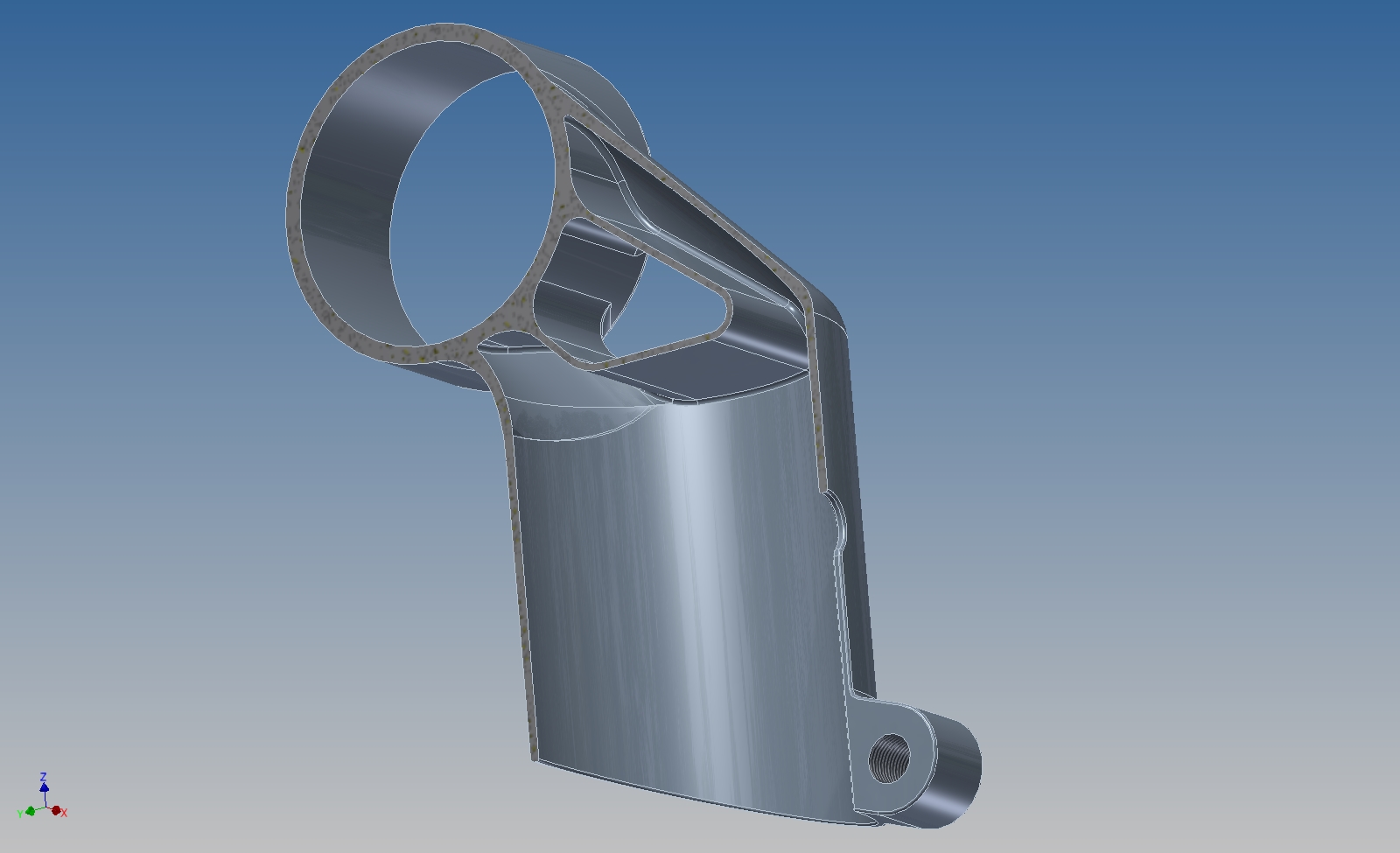
You'll also notice that I removed the little ledge around the perimeter of the inner diameter of the part. It was originally intended to be a hard stop for the seatmast to bottom out on, but I was able to eliminate it - while retaining the core function - but moving the window's bottom edge to the same plane.
The result is much more organic, and distributes strain more evenly around the part. I'm not totally done fine-tuning it, but the initial FEA results are promising.
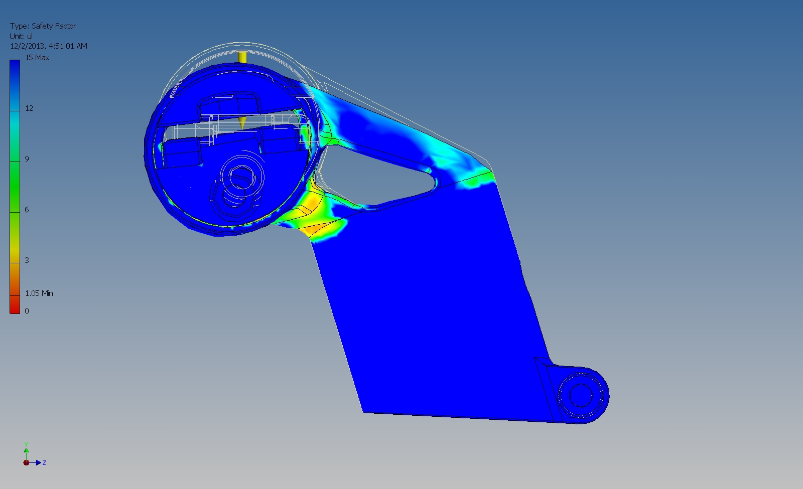
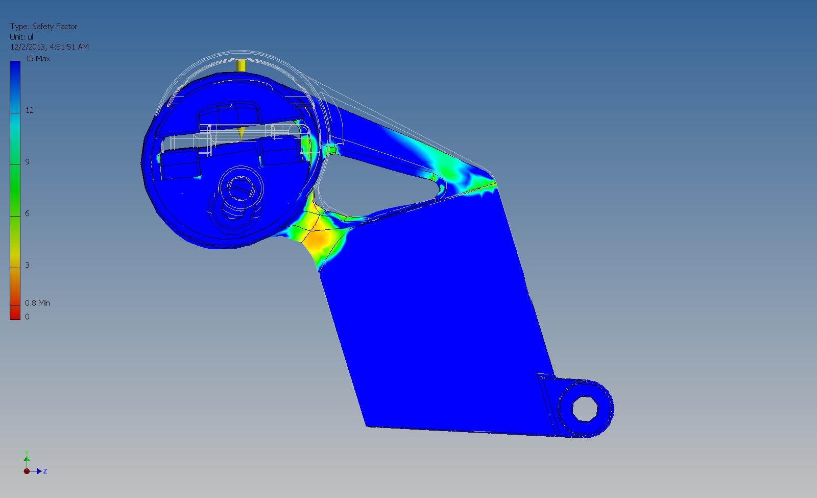
As you can see, the corners of the lower section are stronger now, and strain there is more evenly distributed. And because of the way I rebuilt the model, it shouldn't be too hard to beef up the necessary portions a bit.
Although I'd like to take another shot at some of the loft geometry, I've been thinking ahead a little too. I suspect that the clamp portion can be relieved a bit, and have been playing with some shapes... I rather like the result :)
Too Many Sketches
I've been working on optimizing the Topper a bit, which has involved starting from scratch and remodeling the loft a little smarter.
...But it's getting complicated. There's *way* too much here, and this is a stripped down version of what I had last night.
Basically, NURBS surfaces kinda suck - building this loft is a PITA. I would try this in Fusion 360 with T-splines... but I'm hesitant. Last week's version was pretty close to where I wanted it, and I thought that I could rebuild it quickly and move on. My work this morning will tell whether I was wrong.
Stress
This is modified a bit from last night. Fillets, window dimensions, and a few wall thicknesses are revised. Overall effect is that it's lighter and stronger.
Still more work to go, but it's getting there :)
Oh - and this simulation is 2000 Newtons - about 450 pounds-force.
Topper taking shape
Made a bunch of changes to the seatmast topper last night.
I ended up rebuilding the entire lofted body, which is basically the whole middle section of the part. Doing so allowed me to modify it down the line, which is really useful when building NURBS surfaces. After making the outside shape, I ended up needing to tweak it a lot to avoid collisions with later features. Accommodating these changes is hard to do, though - you kind of need to know what the part is going to look like before you start. It's a real chicken-and-egg problem. What usually ends up happening is that you don't do it right until you've rebuilt the whole model three or four times, which is about where I'm at here :)
It's hard to describe, but the upper section is hollow. I also spent a while trying to optimize around shared surfaces, so the window upper & lower walls coincide with features that I already needed on the part. The one thing I'm not particularly happy about is the seatmast clamp at the bottom of the part. The details are a little different, but overall it's designed the same way it would be if the part was welded. This part is going to be 3D printed, though, and I'd prefer to find a way to build the feature in a way that directly addresses its manufacturing method.
But overall, the part is definitely forward looking. I'll post a section view later, but for now just take my word that most of the middle of the part would be impossible to make by any other method than additive manufacturing. Also, right now the topper body (just the gold part, not including hardware) comes in at 74g, and I suspect that with a little work I can shave that even more :)