A few weeks ago I visited CIMP-3D by invitation of its co-director, Dr. Tim Simpson. I was there partly just to visit (I love these kinds of places), but also to see first-hand the role that CT scanning can play in non destructive testing of additively manufactured parts.
CIMP-3D is located at and operated by Penn State University, and serves as part of Penn State's Applied Research Lab - and as an Additive Manufacturing Demonstration Facility for DARPA. In aggregate, they help both government agencies and commercial partners qualify and improve parts made by powder bed fusion and directed energy deposition. In their well-equipped shop, they have two powder bed fusion machines: an EOS M280 (EOS calls their process "DMLS", a term that I continue to get flack for using generically :) and a 3DSystems ProX 200 (3DSystems calls their process, which was developed out of their 2013 acquisition of Phenix Systems, "DMP" - for "direct metal printing). For their work on directed energy deposition, they also have an Optomec LENS MR-7 (a laser based powder deposition machine), and until recently had a Sciaky EBAM (a large scale wire fed electron beam welding machine, which had been sold just prior to my visit).
While I was excited in see their directed energy deposition machines, the real attraction was their GE phoenix v|tome|x m300 CT scanner. This machine is made by GE Measurement & Control division, which is part of GE's Oil & Gas business unit (it should be noted that I've done consulting for both M&C and O&G, though not for the people who make CT scanning equipment). CT scanners are *expensive* (close to $1M, depending on options), and are basically unheard of in private service providers. They can be used to analyze both the as-built form of a part (which will often deviate from the as-designed form significantly), and also any flaws (cracks and voids) which would make it unusable.
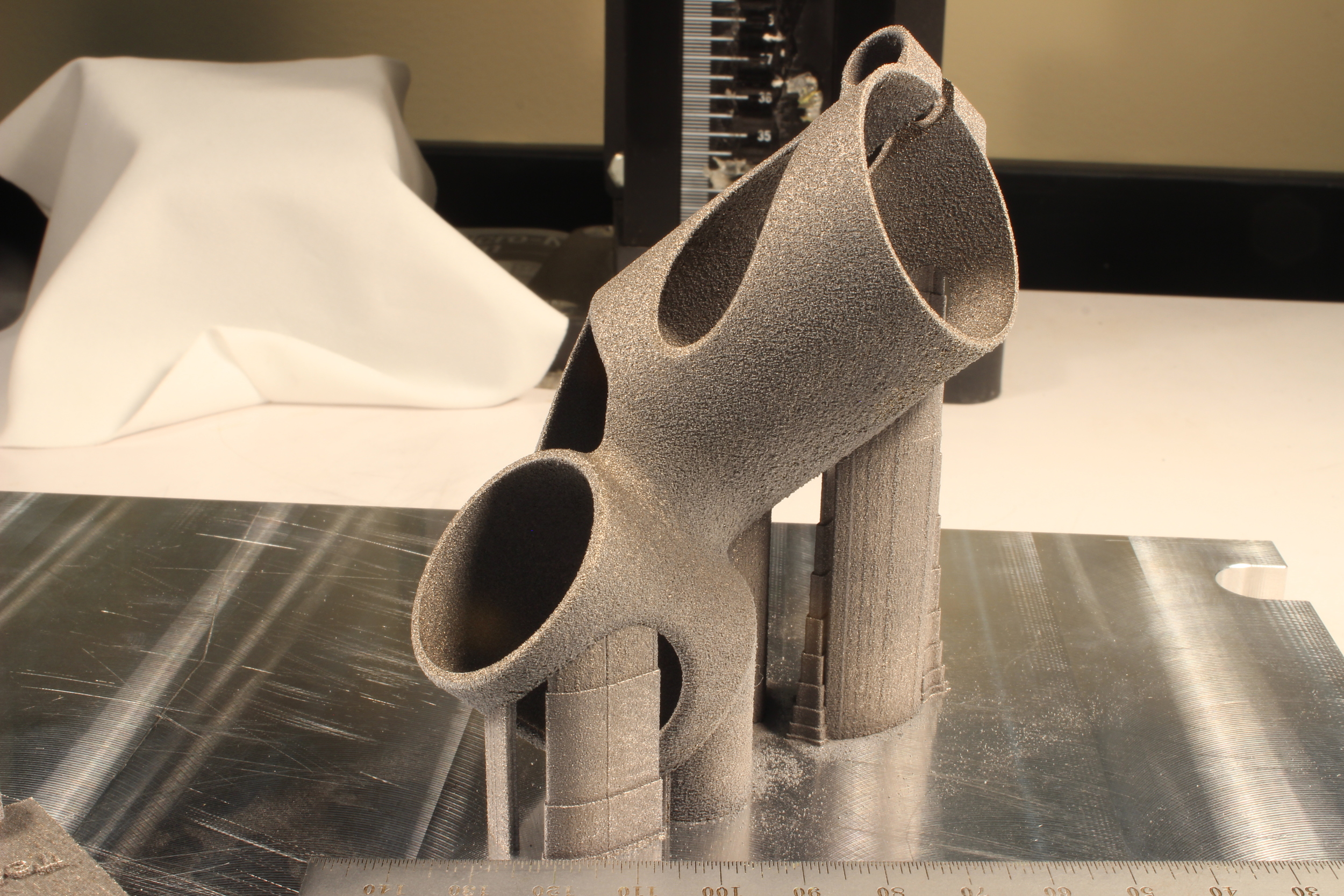
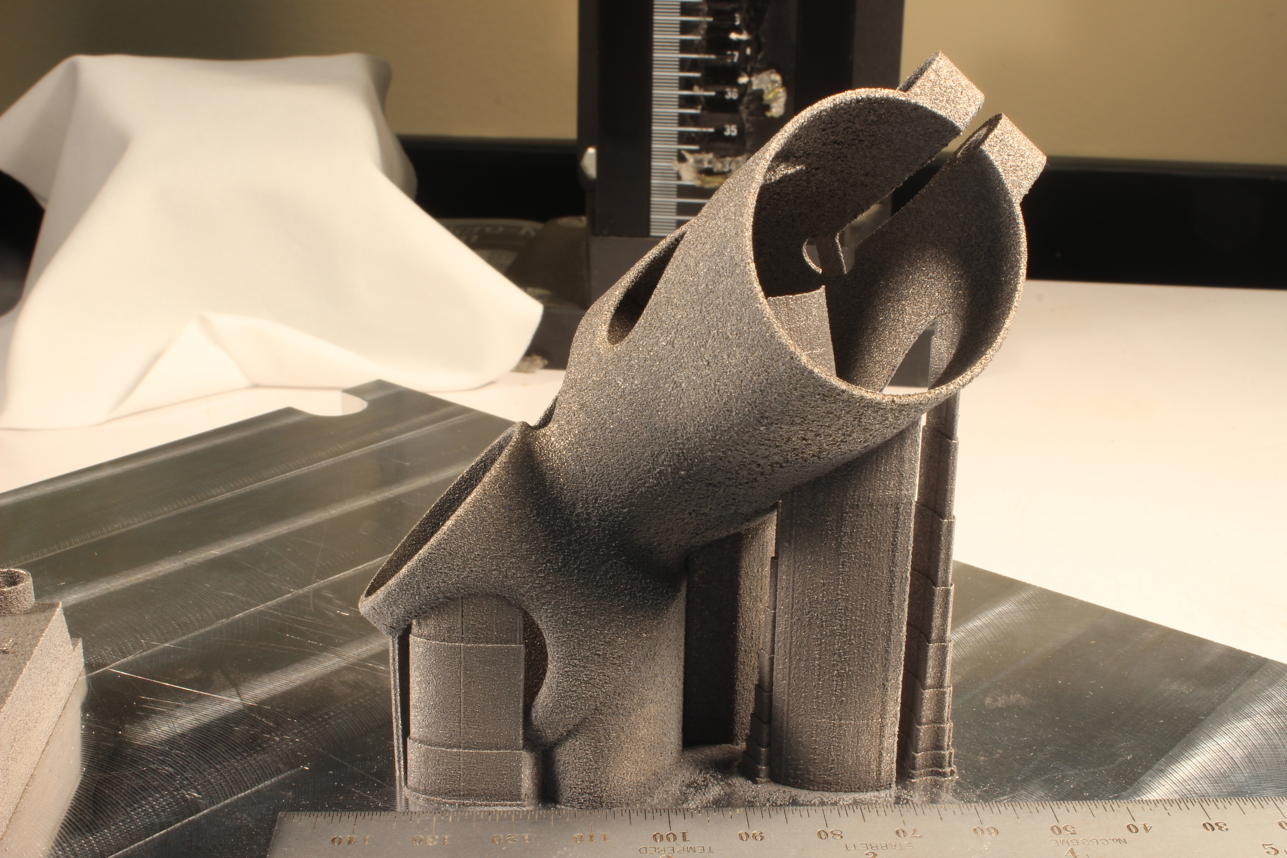
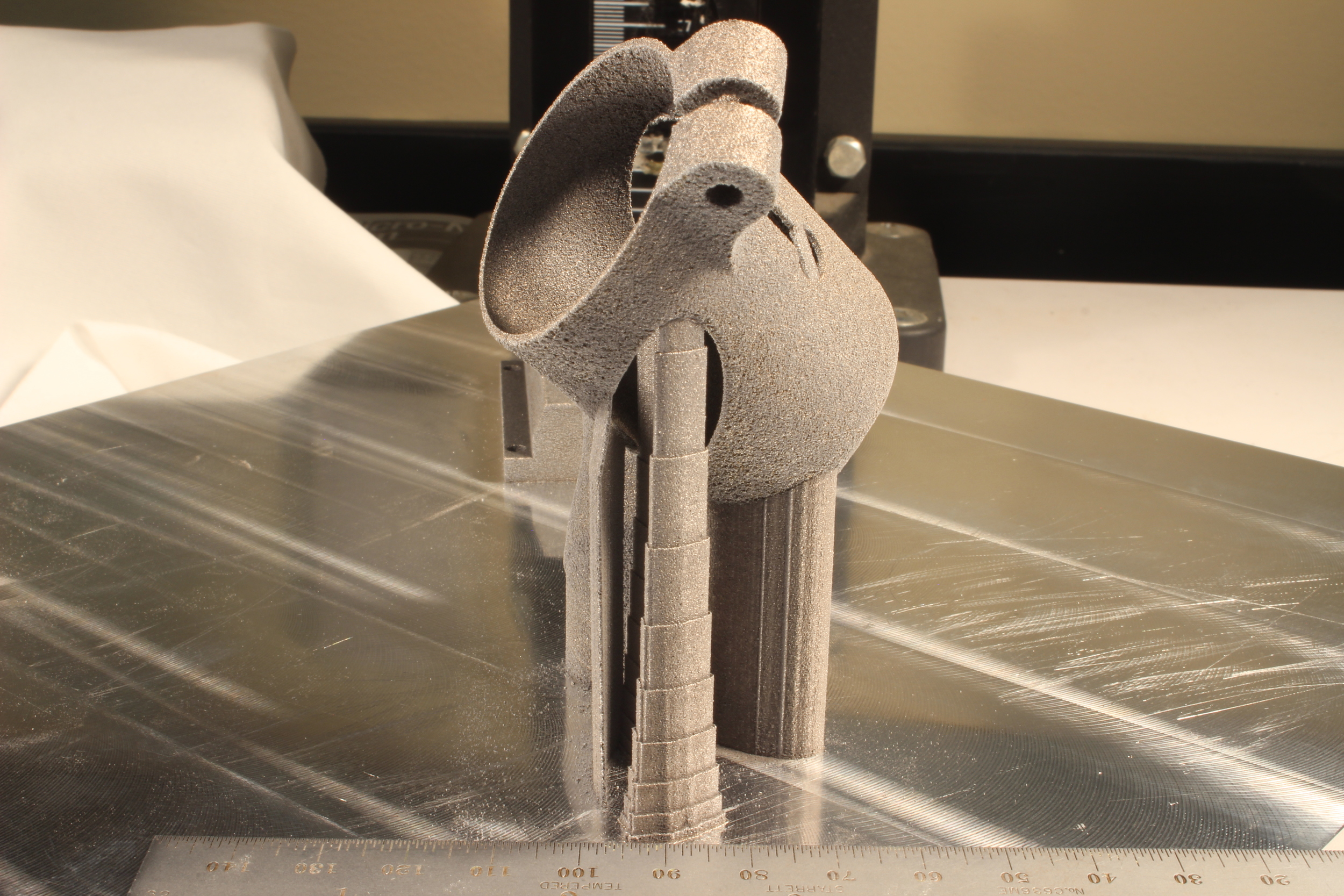
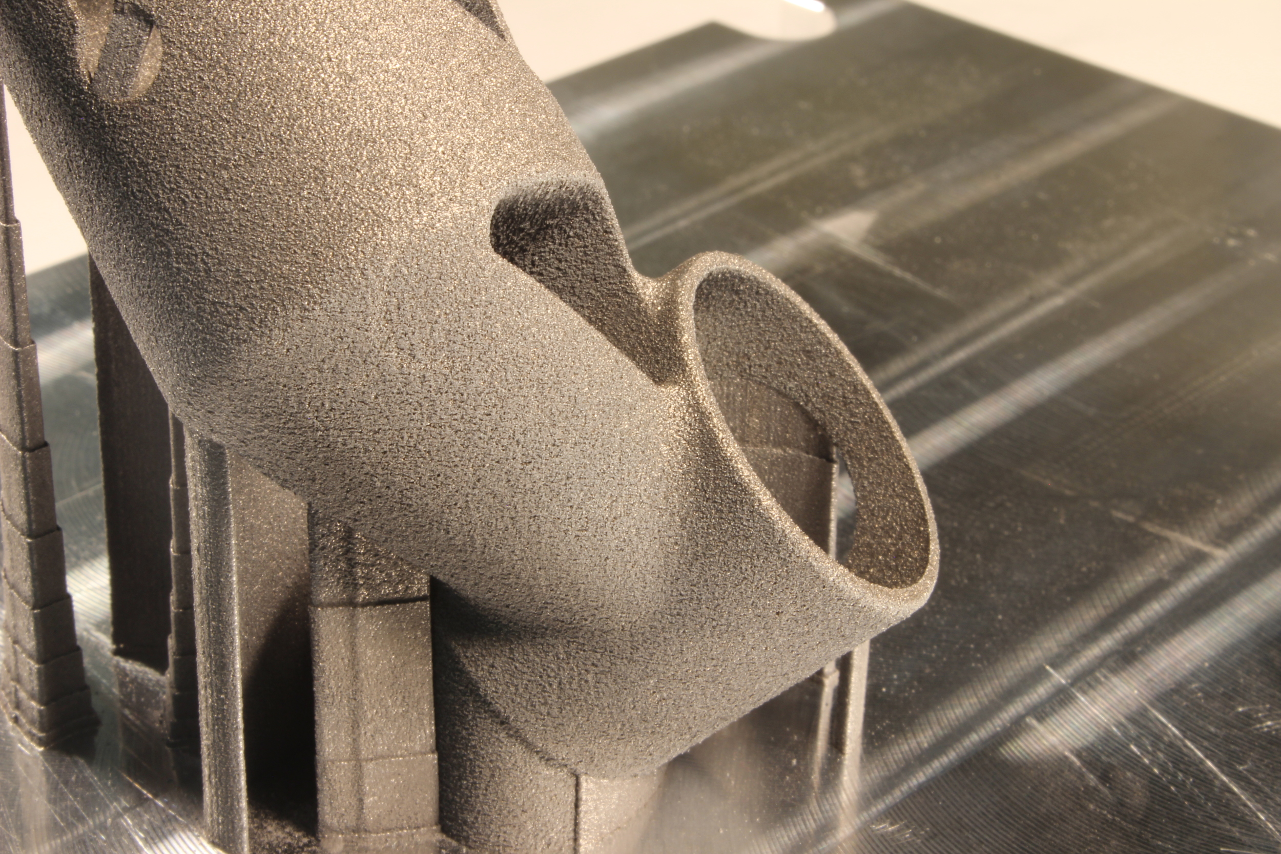
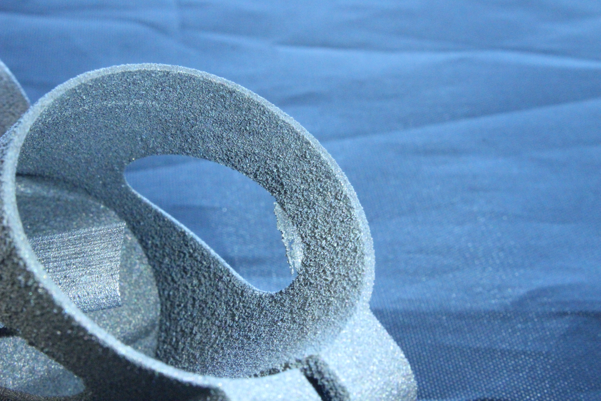
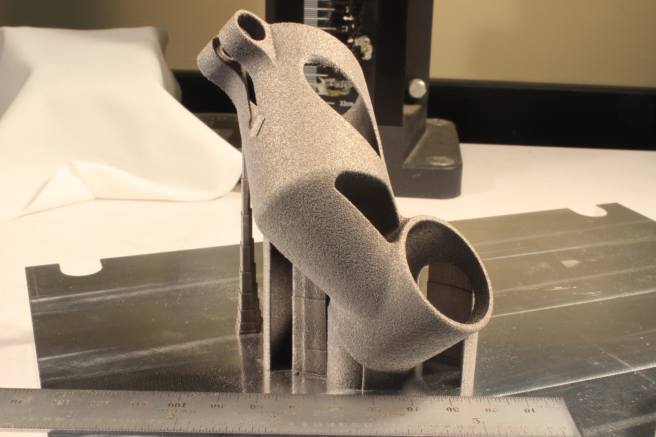
Before I visited CIMP-3D, Corey Dickman (an R&D Engineer there) was kind enough to print one of my seatmast toppers, in aluminum, on their EOS M280. It came out well, with only a small defect in the seatmast clamp area. Corey used some pretty clever support structures, tapering them in order to provide a balance between a solid grip on the plate on the one hand, and relatively low material usage on the other:
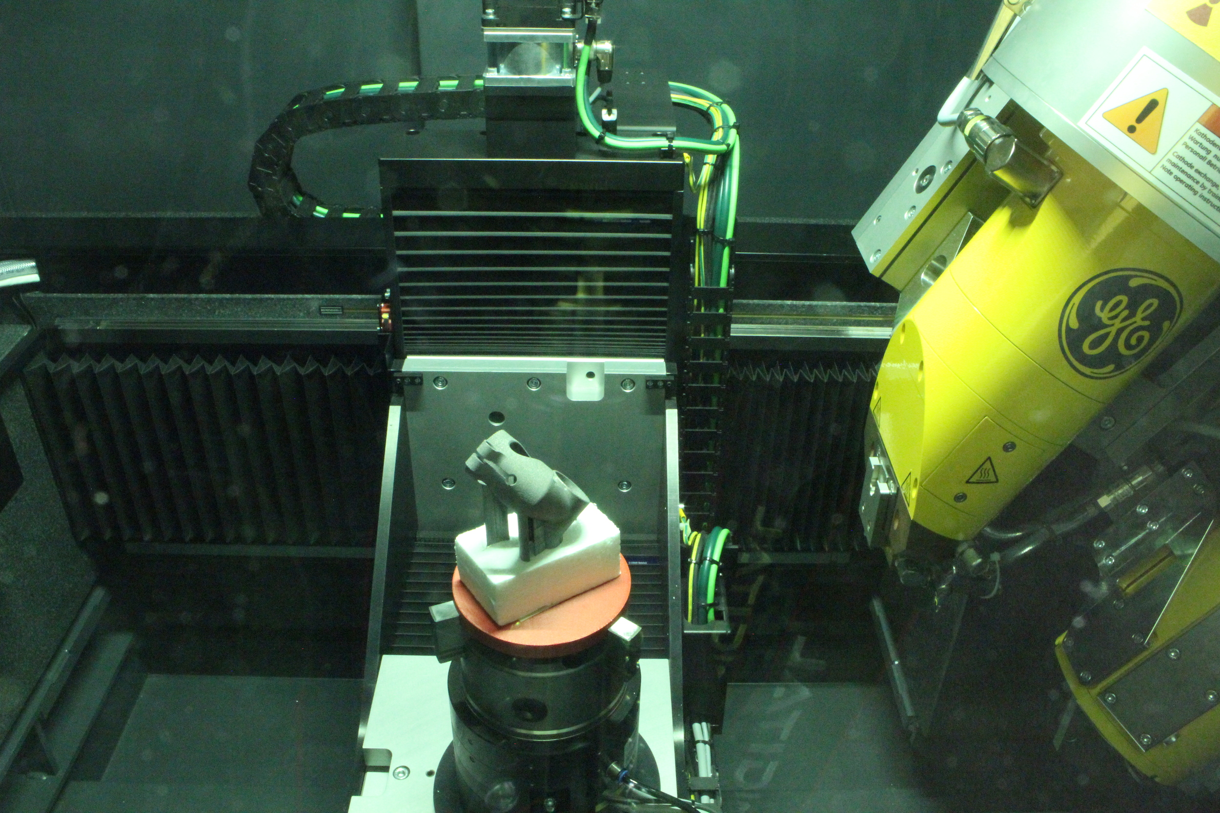
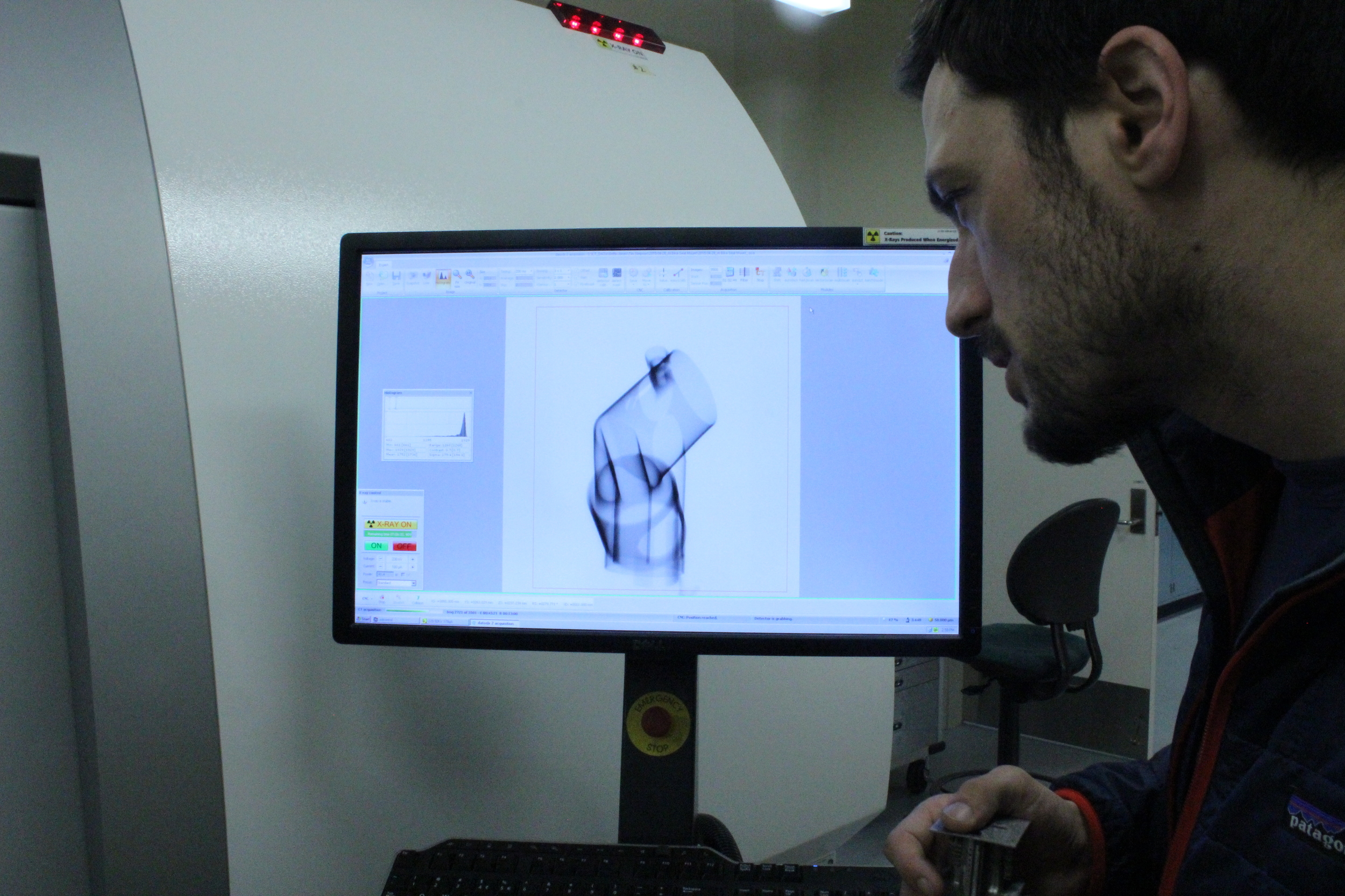
CT scanning uses a series of 2D X-ray images to reconstruct a 3D part. In CIMP-3D's scanner, the part is placed on a turntable in the middle of the machine. The X-ray projector, on the right side of the machine, shines X-rays through the part onto a sensor on the left side. Solid parts block X-rays, creating shadows on the sensor, and the result is a greyscale image where dark areas correspond with solid mass and light areas correspond with empty space.
The scan moves pretty slowly. My part was scanned in 3500 slices, or one scan every ~.1 degrees. At this rate (and at a voxel size of 58µm), the total scan time was about an hour. Each scan takes about a second, and between scans you can see the turntable rotating slightly.
Fixturing the part in the machine presents an interesting challenge. You want it to be held securely, but you don't want any other solid things touching it - as they will cast their own shadow in the X-ray images. As a result, parts are often held in place by simply sticking them into a piece of styrofoam - as mine was.
Once the data is captured, it's loaded into a separate workstation to be reconstructed. The amount of data that needs to be processed here is staggering - my scan generated about 25 gigabytes of image data, which reconstructed into a 5.7 gigabyte model.
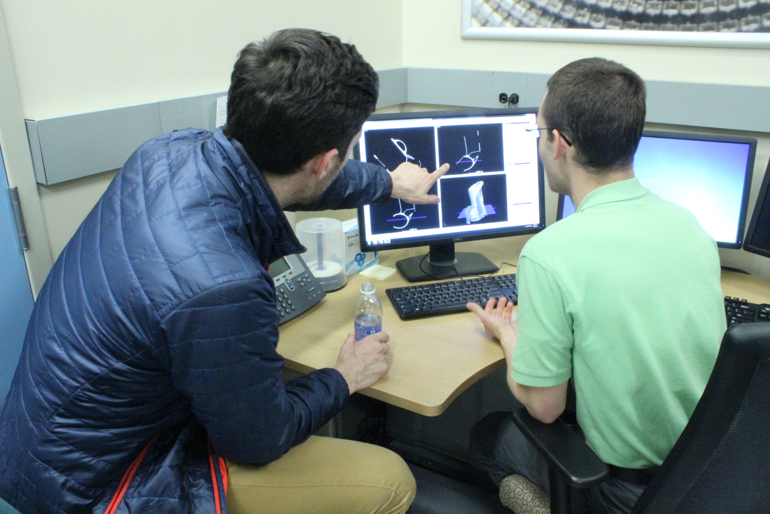
Once the reconstruction was complete, Griffin Jones (the R&D Engineer responsible for CIMP-3D's CT scanning) was able to do a visual analysis of the as-built part, checking it for voids and flaws. The as-built model can also be overlaid on top of the as-designed model, allowing for deviations to be easily quantified. The model can also be explored layer by layer in any orientation, allowing for a really complete understanding of what the solid part looks like:

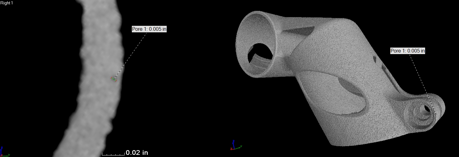
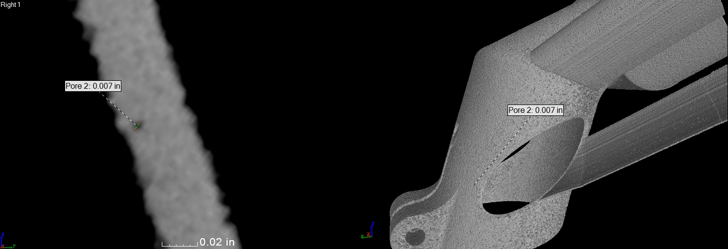
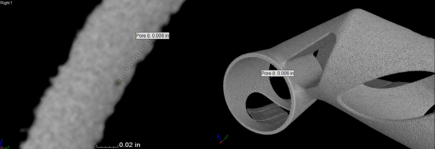
A word on resolution: this scan was performed at a voxel size of 58µm, and each voxel is assigned a greyscale value that corresponds with the material's radiographic absorption coefficient at that location. However, any given voxel is subject to some amount of randomness as well; if a voxel has a vastly different value than its neighbors, then the operator needs to determine whether that's a result of a microscopic void, or a result of random variations.
As a rule of thumb, Griffin assumes a void when he sees three voxels in a row with low grey values. Interestingly, the scan did reveal a few tiny voids in my part. They're mostly near the edges - specifically, the zone right at the boundary of the profile scan (the perimeter of the part's cross-section) and the infill hatching. Since the scan was performed at a voxel size of 58µm, and Griffin was looking for three voxels in a row with low grey values, the voids we detected were about 180µm - just larger than the diameter of a human hair.
My suspicion - which would need to be verified by destructive testing - is that voids of this size are probably well within the functional requirements of my design. Of course, this particular model is aluminum, and the design is meant for titanium - but I'm looking forward to having a ti model scanned and destructively tested in the future.
For most product development teams, non destructive testing (NDT) is just one part of the process of qualifying a new part. My part, for instance, is being put through physical load testing this week - and I'll use the data I get from that test to improve my design. But for early on in the build planning process, having a tool that allows you to dive inside otherwise obscured areas of your part is incredibly helpful. Especially in the case of complex, topology-optimized parts with organic forms, it can be difficult to impossible to measure a part's deviation from the underlying design. Moreover, there may be regions that it's impossible to inspect without destroying an expensive prototype. My part has just this: the front of the neck section contains a completely hidden hollow zone. And as I move into redesigning for EBM, knowing the areas where powder tends to cake up will be even more helpful.
Thanks so much to CIMP-3D for hosting me!