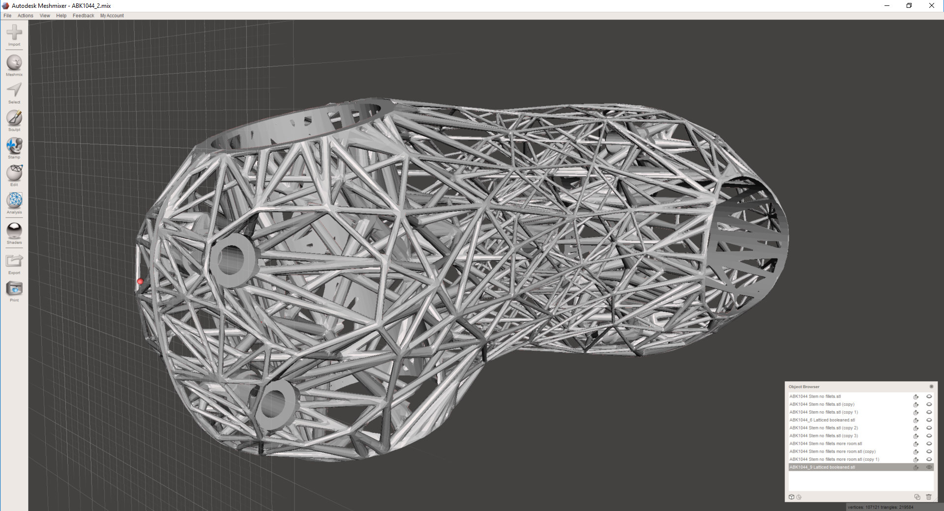
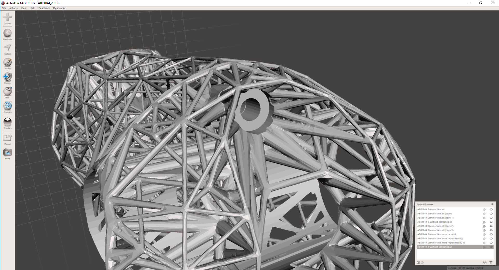
A friend asked me yesterday what was going on with my lattice bike stem design, and after telling him that it's been on the back burner I played with it a bit and made some real (if subtle) improvements.


First, I should note here that I'm *not* worrying about overhanging faces. That's mostly because I'm working at nTopology to break down manufacturability of lattices into its component parts, and am tabling all of my DFM concerns until I have real data to back them up. In addition, I'm focusing on using variable thickening to maximum effect right now. I've used variable thickening a lot in the past, but the next software update of nTopology Element pushes it even more into the forefront, and I want to dogfood myself a little before we release it into the public :)
I don't have screenshots of the whole process, but this part was designed in much the same method that I was using last fall. I used Inventor to make a design space, and Meshmixer to generate surfaces to grow a lattice on. Then I used Element to:
- Create a surface lattice with beams at every edge in the Meshmixer model
- Create a volumetric lattice (based on a hex prism cell shape) inside the part
- Merge the two lattices by snapping nodes on the volumetric lattice to nearby nodes on the surface lattice
- Creating attractor modifiers at locations that I know I'll need more thickness in my lattice, e.g. mechanical features
- Applying variable thickness to the lattice based on those modifiers
- Refining the resulting mesh & reintroducing mechanical features via Booleans
The trickiest thing by far here is setting the attractor modifiers to the right range & falloff. I've got three things going on here:
- Bolt holes. These need to be maximum thickness (1.5mm) to accept threads and distribute the load from the bolts.
- Clamp surfaces. Where the stem clamps to the steer tube and handlebar, the part needs to have relatively high surface area. All lattice beams should lay on the surface itself, and thickness should be high as well.
- Mechanical stress. I haven't done a full analysis of this part, but in general stress will be concentrated near the clamp surfaces and will be lower in the middle of the part.
Clearly this blog post would be more effective if I ran through every attractor one-by-one and explained how editing them changed the resulting structure, but we'll have to forego that for now. Suffice it to say that the part above weighs 105g and has roughly the mass distribution I was looking for; I'll update with more details soon :)