Screenshots from both Zach and myself - we've swapped back and forth on layout duties.
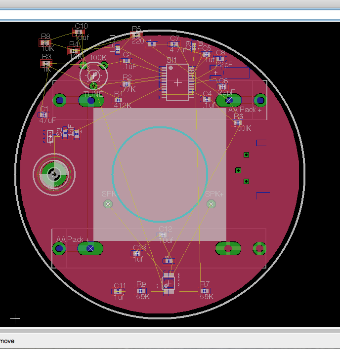
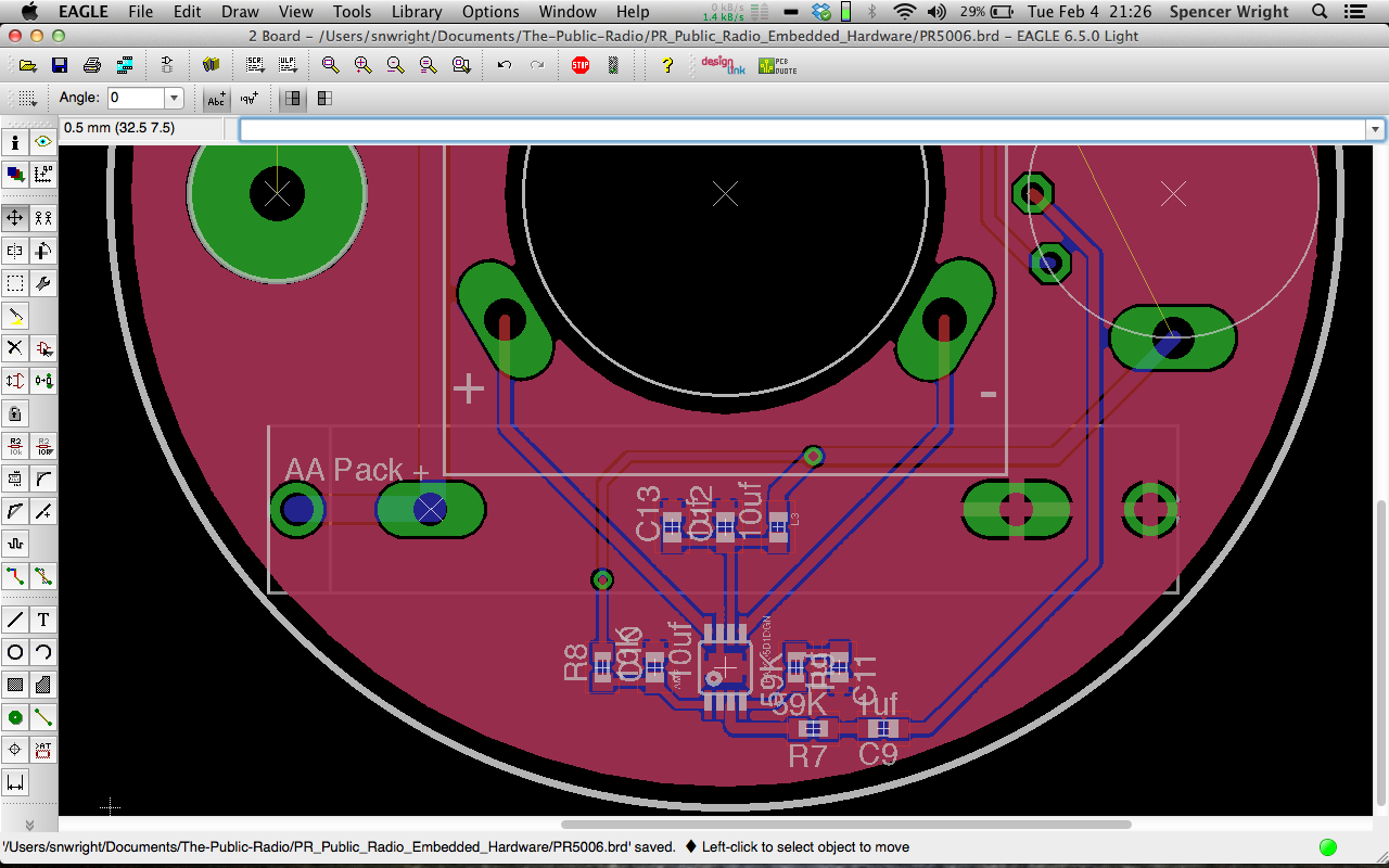
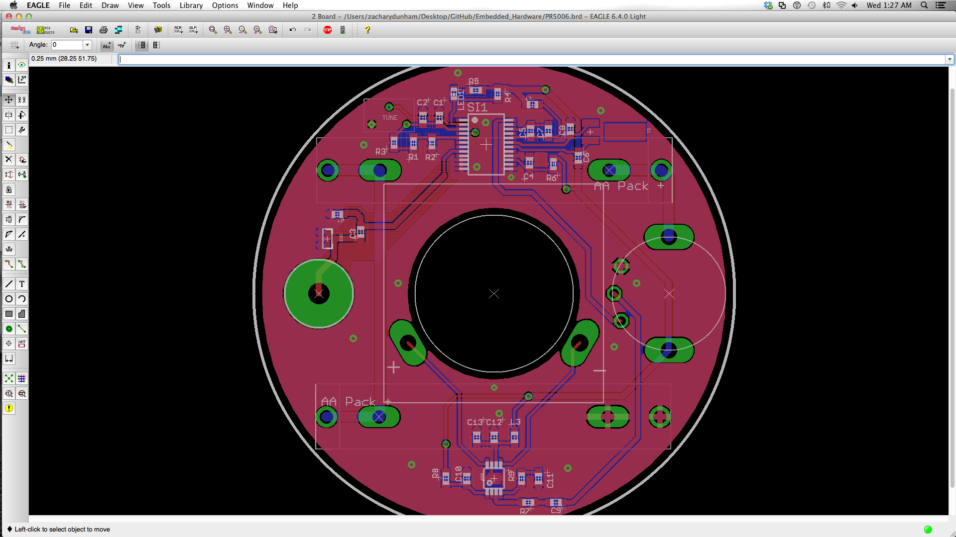
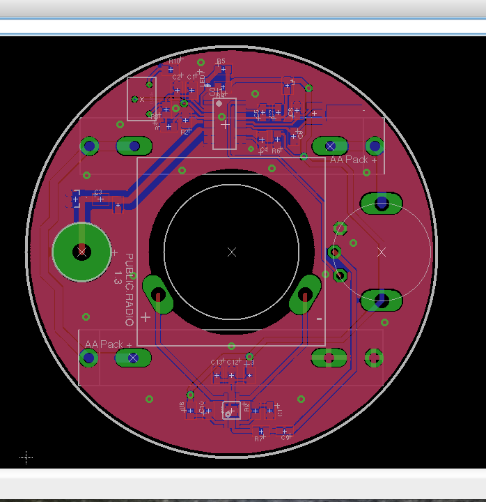
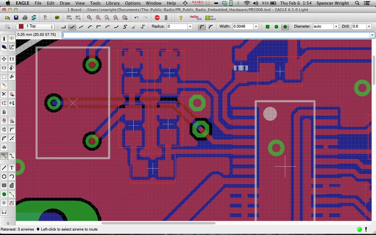
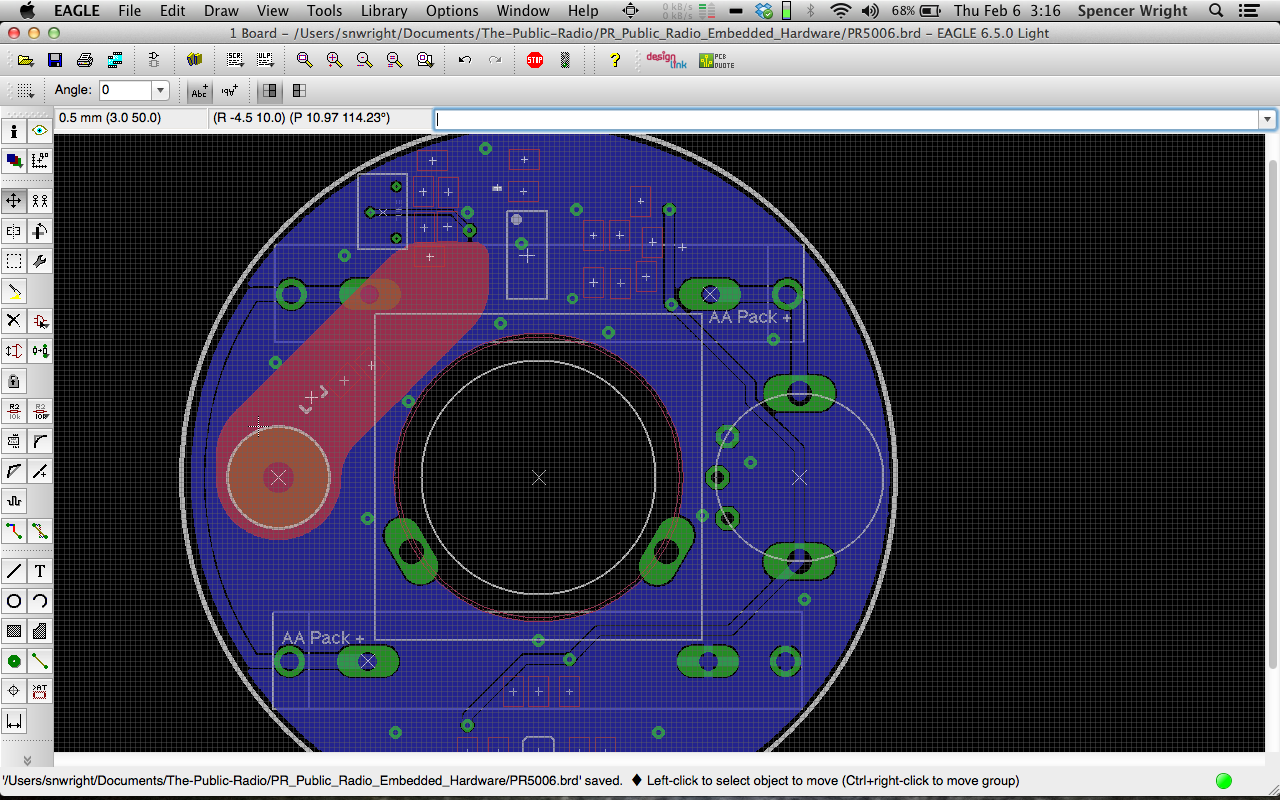
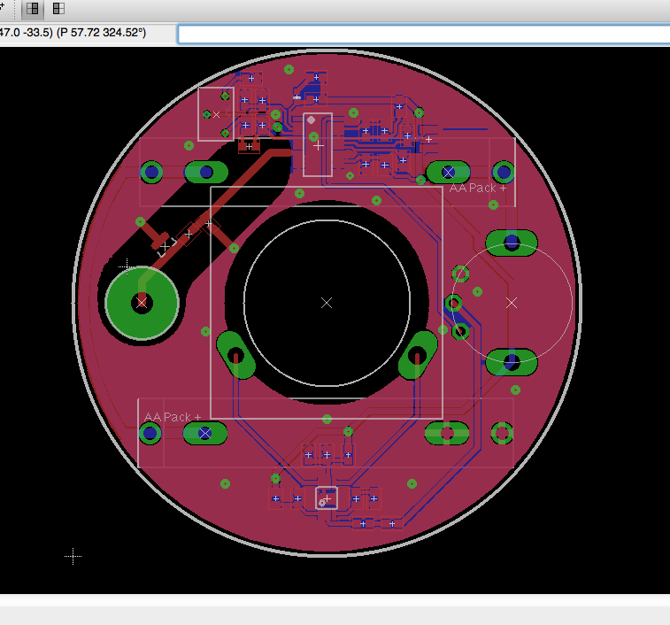
The FM IC (Si4831) is at the top of the board; to its left is the tuning circuit and trimpot. On the right edge of the board is the power & volume pot, and on the bottom is the amplifier, and on the left is the antenna connector. The middle of the board has a big cutout for the speaker body to fit through; we'll solder the speaker terminals directly to the board.
I got a little cute with the restricts near the antenna trace, and ditto on the power trace along the left edge of the board :)
Meanwhile, I spent a little time today modeling the battery connectors in Inventor:
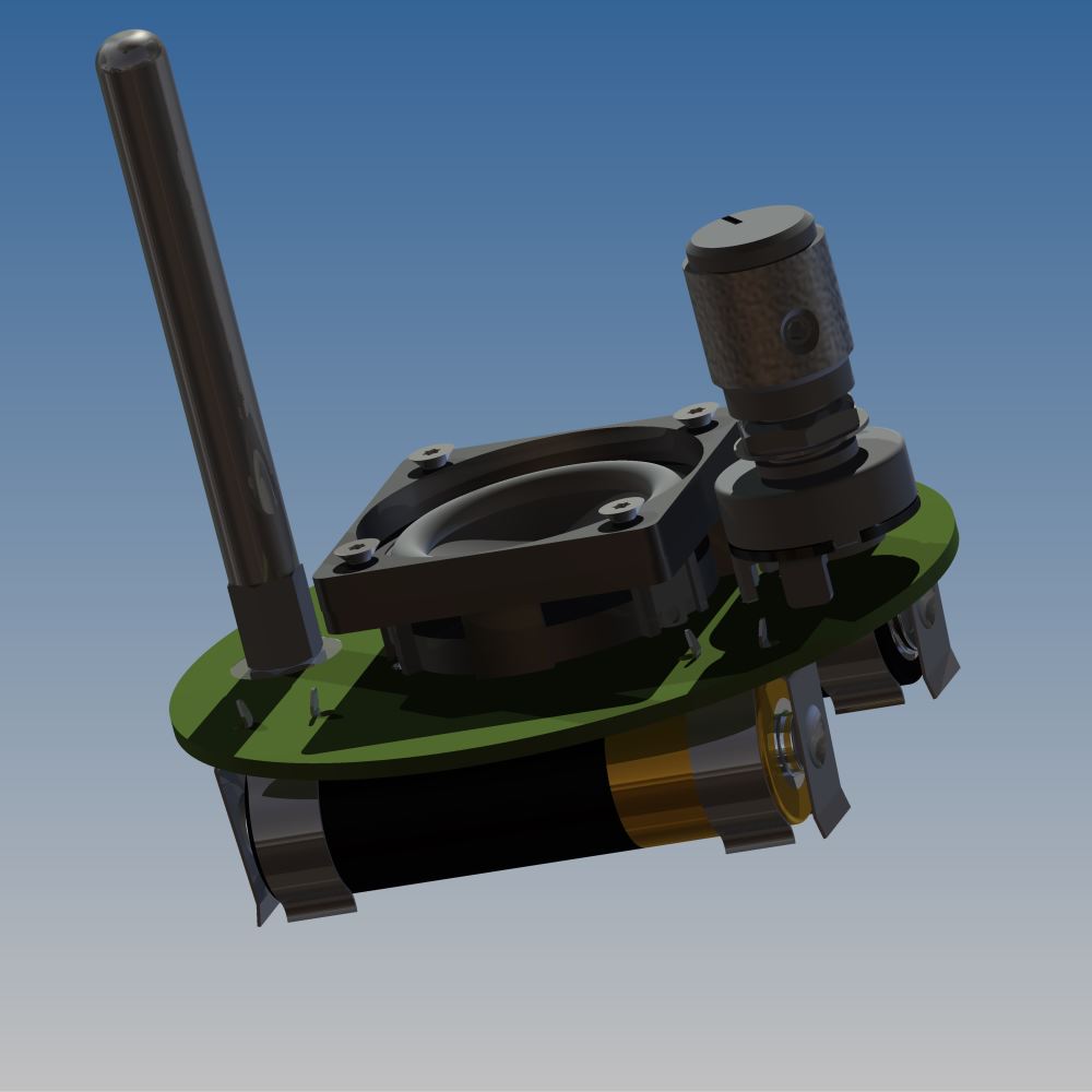
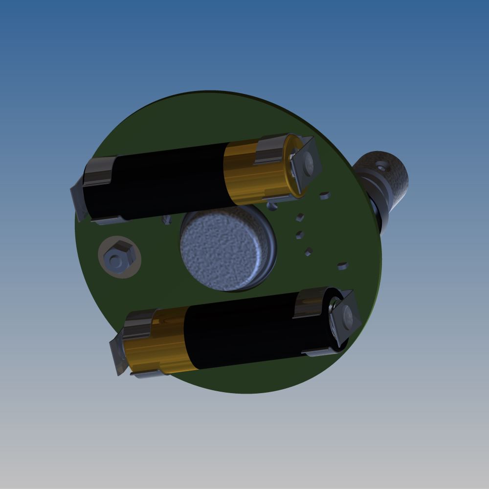
Finding nice through-hole AA battery connectors is *tough.* I'm hopeful about these - I think they'll hold the cell firmly but allow for easy removal too. The only downside is that they're not polar in any way, so we'll need to mark the PCB clearly to show which direction the batteries need to face.
Our antenna standoff is kind of exciting too. We're running a trace to a plated hole (with a *big* pad) on the PCB, and then fastening a male-female threaded standoff to the hole with a hex nut. The antenna itself will thread into the standoff, making it easy to remove/install for shipping, transportation, etc.
We're in the process now of getting quotes for a couple of custom pieces of hardware: the antenna, the knob, the potentiometer, and the speaker gasket. We've also gotten a few quotes for the lid, which will either be stamped or laser cut stainless steel. And when PCBcart comes back from Chinese New Year, we'll order a batch of new boards to get into the hands of our beta testers.
This is an exciting time in the project. Things are coming together quickly :)