Just a quick update to yesterday's post - here are some screenshots showing a little bit of how I'm controlling thickness on my lattice stem.
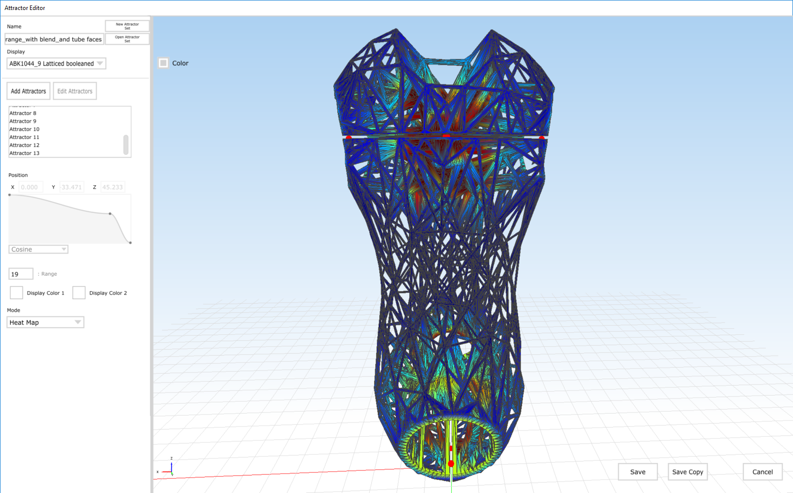
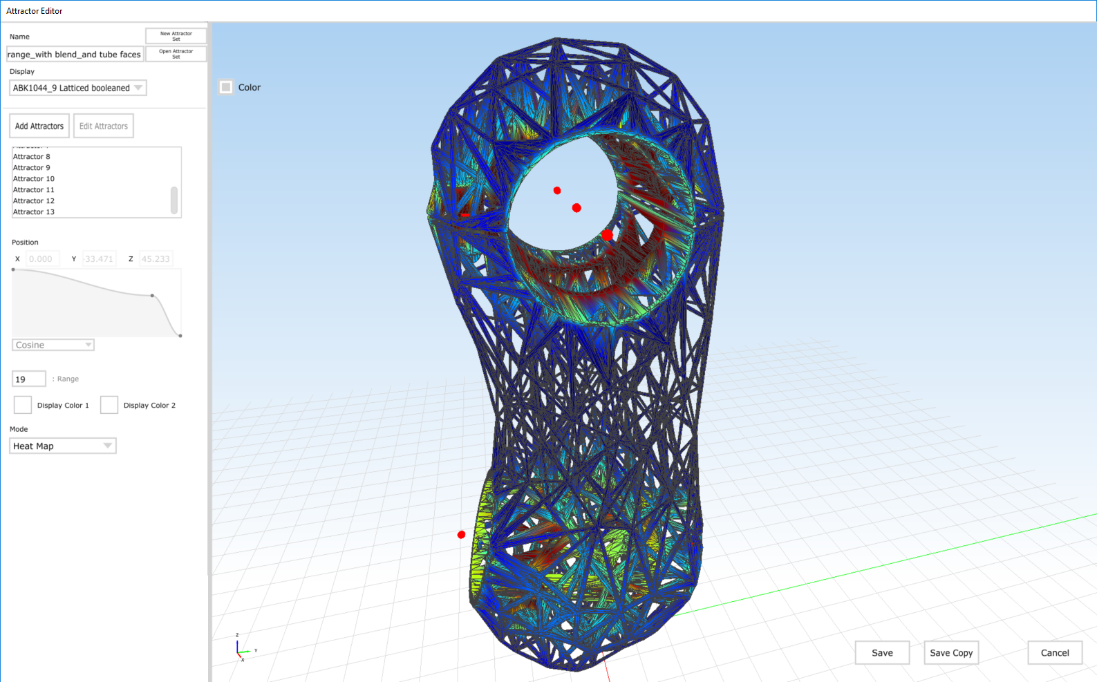
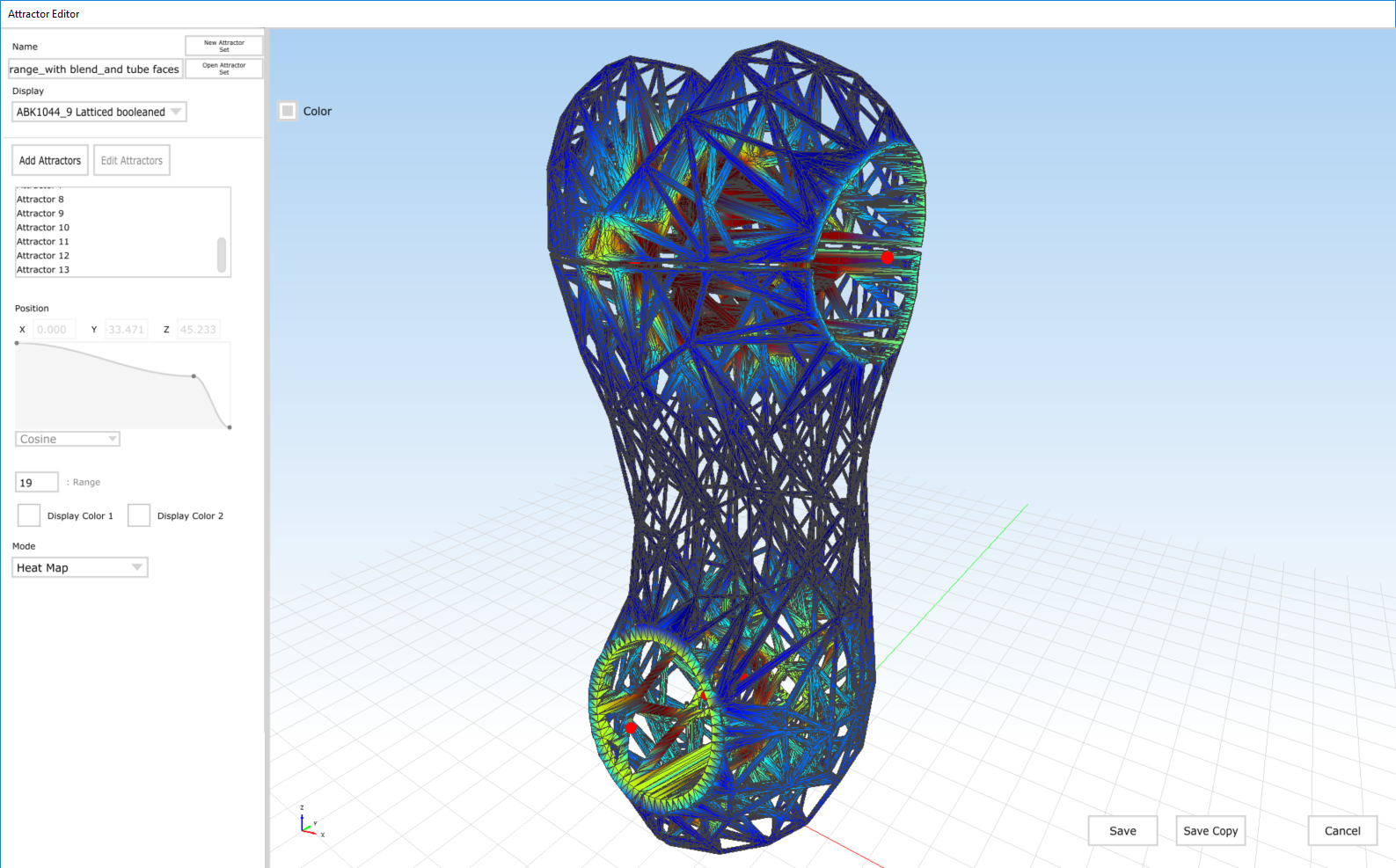
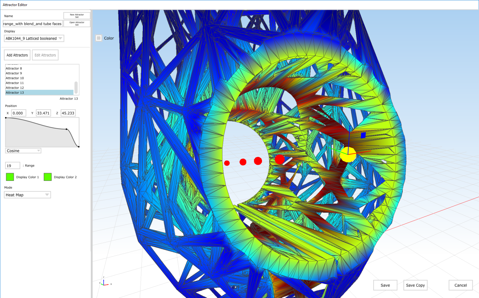
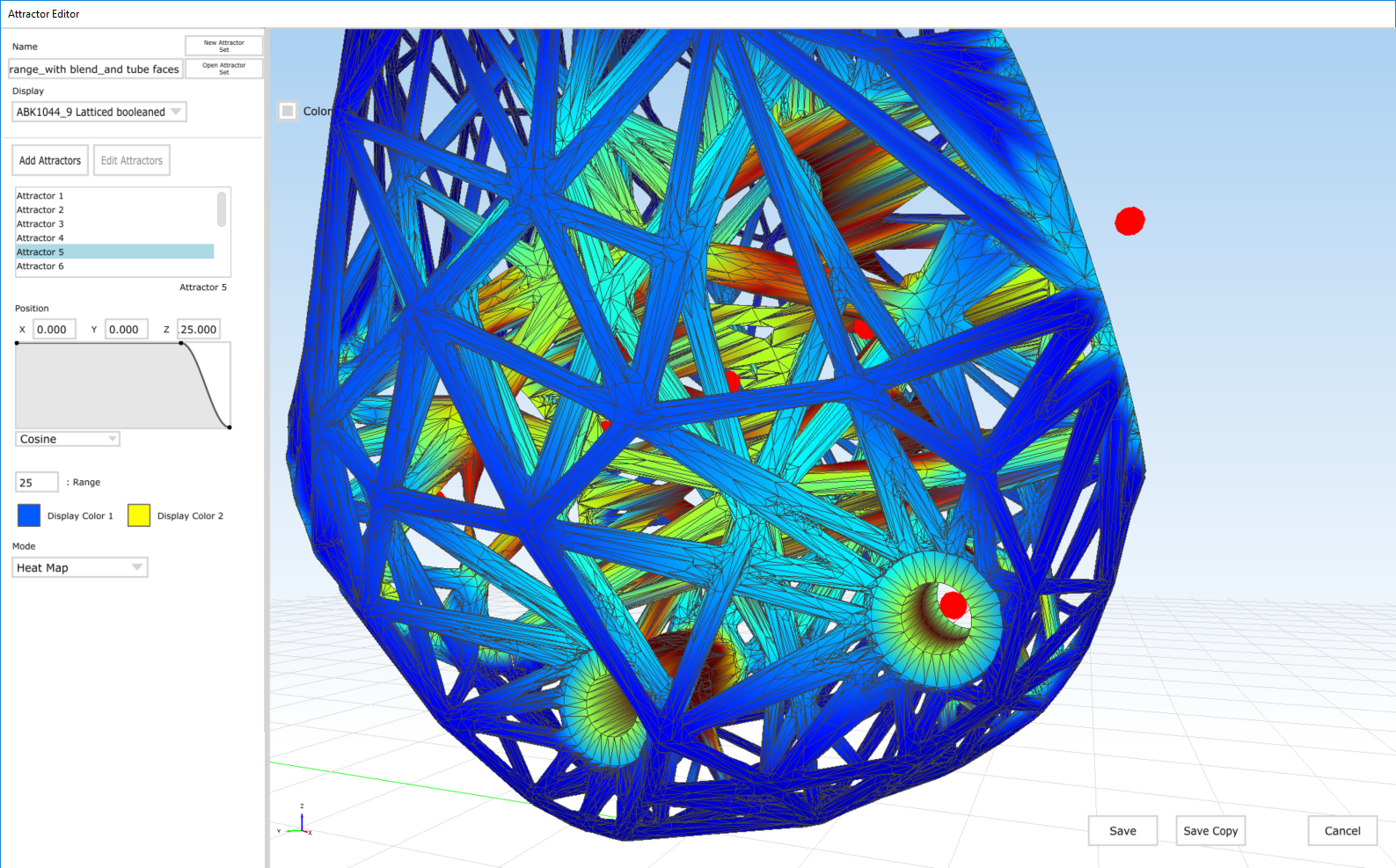
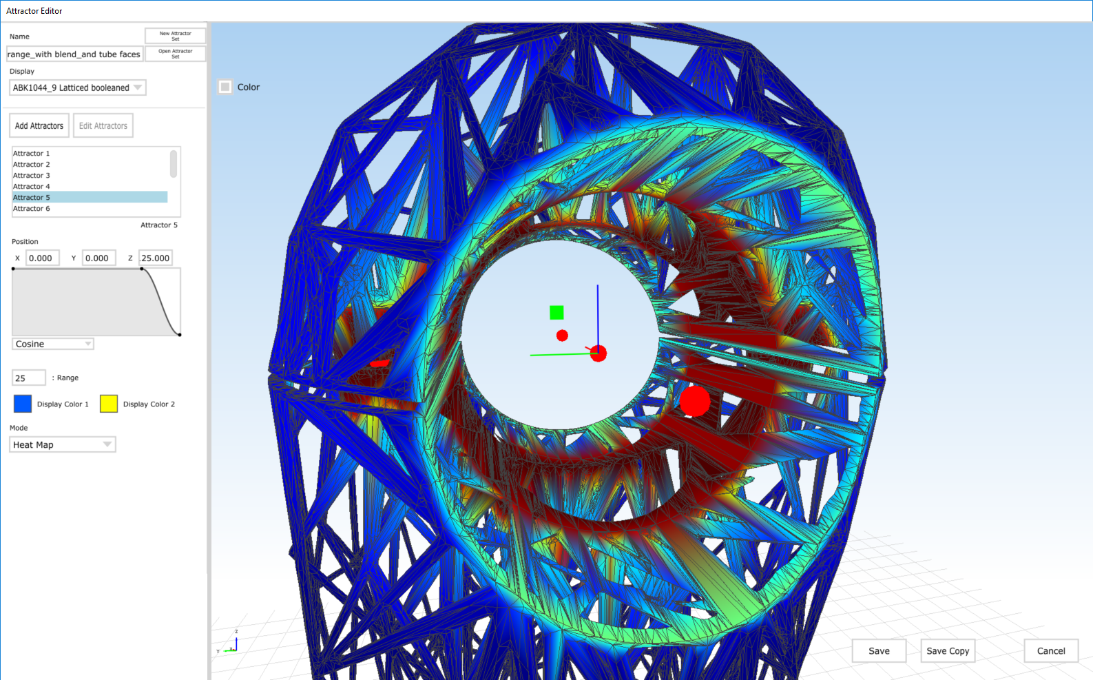
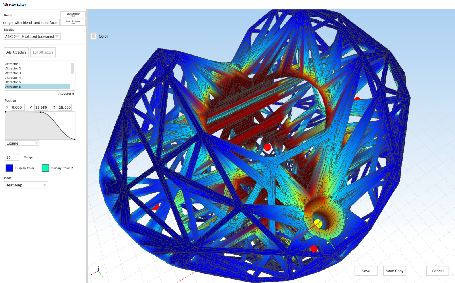
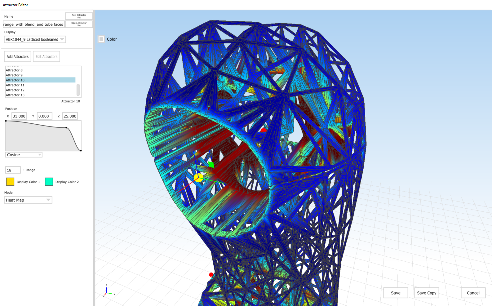
Our variable thickening algorithm allows the user to input minimum and maximum beam diameters. If a beam isn't within the range of any point modifiers, then it's thickened to the minimum value. If it's within range, then its thickness is determined by the falloff curve of the modifier that it's within range of. If it's within range of multiple point modifiers, then the greater thickness value is used.
As you can see above, the Modifier Editor allows the user to preview the effect that the modifiers will have on a part; blue means that a region is not within range of a modifier (and will be the minimum thickness), and red means that it's within range (and the maximum thickness will be applied). We allow you to preview this on any mesh in your project. Here I'm looking at a variably thickened lattice, but generally I'd start with a uniform thickness lattice and then play around from there.
The big change in the design yesterday was adding point modifiers in four locations: On either side of the handle bar clamp, and on the top and bottom of the steerer clamp. These modifiers have steep cosine falloff curves, meaning that they have a big effect on a relatively small region of the part. I've controlled the range and falloff so that just the beams on the edges of those surfaces are affected.
I also have point modifiers at all of the bolt holes, and a few that control thickness on the rest of the clamp surfaces, and then two point modifiers that make the transition from the clamp surfaces to the center of the extension a bit more gradual.
We've been thinking a bit more about how to develop modifiers in the future - stay tuned!