Manufacturing guy-at-large.

Stainless steel bike

Added on by Spencer Wright.

This is from a while ago - late summer 2010. At the time, it was one of my proudest pieces of physical output, but somehow I never got around to properly sharing it on the internet. I never photographed it properly either, so these iPhone shots will have to do for now :/

I love the belt drive, but am now quite a bit less enamored of the Alfine setup. The frame is pretty awesome, though (it's all Reynolds 953 mar-aging stainless steel), and I'm *really* proud of the racks. 

This bike was the real impetus for me to make my own rack ends. I also made a few other little bits on the bike, including a pretty cool seatstay bridge with hidden fasteners for the rear rack.

Incidentally, the mushroom-head velcro on the front rack is a pretty slick way to attach commonly used things to a rack surface. 

Powder

Added on by Spencer Wright.

An old photo, taken during a day of boots-on-the-ground research on clearcoatable decals with powder coating.

powder-1.jpg

This process was a PITA but the result is pretty cool. The decals are basically baked right into the frame. The guy I had doing my powder at the time didn't understand the process fully, so I spent the better part of a day there with him, working through it.

Scheming on Hario shit

Added on by Spencer Wright.

Last week, with Jace.

An early idea of mine was to replace the whole drive bolt on the Mini Slim (there's no reason it couldn't be a hexagonal drive) but ultimately that'd be costlier and would require a lot more disassembly/reassembly by the user.

If you've struggled with your Hario grinder in the past, hit me up!

Plate rack ends

Added on by Spencer Wright.

As described here, my 4-A rack ends grew out of a much simpler design that I had watercut out of stainless steel plate in 2010. 

rack ends-1-2.jpg

As it happens, I've got about 40 of these little guys left, and I'm glad to offer them as "cherry on top" rewards for anyone who backs my Indiegogo campaign. If you're a backer, I'll offer you a 50% match on these parts. In other words: you buy 16 of my 4-A rack ends, and I'll give you 8 of these plate ends. Just shoot me an email and tell me how many 4-A ends you've pledged for, and I'll add these to your order for no additional charge. I've only got a limited quantity of these, so give me a holler soon!

These are actually pretty great rack ends, and I'm sure that plenty of builders would get good use out of them!

Seatpost collar

Added on by Spencer Wright.

After doing even more research on DMLS pricing (update soon), I played around a bit today with designing a seatpost collar. 

BK1026 Barrel nut Seatpost Clamp.jpg

The design here is pretty straightforward. I'm using fairly standard barrel nuts and a M5 bolt (I'll steal these from a Thomson collar I have laying around), and the part profile isn't trying to be innovative either.

I'm getting this printed in alumide (a mixture of nylon and aluminum) for an aesthetic/basic form/function mockup, and will look into pricing on the part too. I suspect that it could be relieved in a bunch of places still (to reduce build time & cost) but for now I don't care too much - I just want to get a functional stainless or titanium part on a bike ASAP.

Updates when Shapeways ships, probably before Valentine's day.

Hario Skerton Mods

Added on by Spencer Wright.

NOTE: The Hario/Porlex compatible drill adapter shown below is available for sale! You can find it on Shapeways, here.


I got a Hario Skerton manual coffee grinder a few years back, but quickly grew tired of the hand cranking (+ the jumps & catches & spills I frequently had with it). So I retrofitted mine with a nut instead of a thumbscrew, and have happily been using a drill with a nutdriver to grind my coffee.

A friend has the Hario MSS-1B Mini Slim grinder, and he has it even worse: The shaft has a pentagon stud, which has a loose fit with the stamped handle and is difficult to adapt to a drill. We were talking about his situation this week, and I decided to model a pentagon driver that could be 3D printed and would allow the user to use a drill to grind their coffee easily & quickly.

I realize that this is a pretty small market - people who are okay with having a drill in their kitchen - but I'm curious whether anyone else out there would be interested in something like this. I'll be testing a prototype of the part over the next few weeks; if you're interested, give a holler!

UPDATE: This part worked! And you can buy one for yourself here.

Authorship

Added on by Spencer Wright.

Shia Labeouf (!) writing in The New Inquiry about the future of creative writing:

Careers and canons won’t be established in traditional ways. I’m not so sure that we’ll still have careers in the same way we used to. Literary works might function the same way that memes do today on the Web, spreading like wildfire for a short period, often unsigned and unauthored, only to be supplanted by the next ripple. While the author won’t die, we might begin to view authorship in a more conceptual way: perhaps the best authors of the future will be ones who can write the best programs with which to manipulate, parse and distribute language-based practices.

I found this essay's discussion of the difference between literature and art/music to be really compelling. 

The Public Radio on GitHub

Added on by Spencer Wright.

The Public Radio is now contained on three repositories on GitHub. They're all within the same "organization," which is an improvement over the previous implementation. You can find it all here, and I encourage anyone and everyone to check it out and log issue requests/make whatever contributions they can!

The goal with The Public Radio is to maintain it as an open source project. Currently we've got embedded systems hardware data (BRD and SCH files from EagleCad), Arduino sketches, and C++ libraries all in their own repositories. I'm not certain this is the best way to organize everything, but it's a start. When I look at the physical hardware again (probably not until next week), I'll create a new repository for that and put STEP files there. I'm not sure that DXFs or STLs will make the cut, though I suppose they ought to. We'll see how the hierarchy works out.

We will, of course, sell The Public Radio as a fully assembled product, but we'll also maintain the GitHub repositories and try to support anyone who'd prefer to assemble/hack/repurpose the designs instead. We're also intending to sell a barebones kit - assembled PCB only, I think - and allow users to use their own speaker, UI, and enclosure.

GitHub isn't integrated into my workflow, and maintaining the repos will take a bit of elbow grease on my part - but I'm confident it'll be worth it.

Please check the repository out and give your feedback!

Test Protocols

Added on by Spencer Wright.

From EN 14766:2005: Mountain Bicycles - Safety requirements and test methods, published by the European Committee for Standardization. Reference courtesy Marcus Schroeder (of EFBe, a bicycle testing firm in Germany) via LinkedIn.

The tests described here are roughly what my Topper would need to pass. (I've excerpted here for clarity.)

Note that 4.14.4 applies only to the saddle itself, so the current design wouldn't need to go through that step... but I've got schemes which might change that.

4.14.4 Saddle/seat pillar - security test

4.14.4.1.2 Test Method

With the saddle and seat-pillar correctly assembled to the bicycle frame, and the clamps tightened to the torque recommended by the bicycle manufacturer, apply a force of 650N vertically downwards at a point 25mm from either the front or the rear of the saddle, whichever produces the greater torque on the saddle-clamp. Remove this force and apply a lateral force of 250N horizontally at a point 25mm from either the front or rear of the saddle, whichever produces the greater torque on the clamp (see Figure 48).

4.14.5 Saddle - static strength test

4.14.5.2 Test method

With the saddle clamped to a suitable fixture representation of a seat-pillar and the clamps tightened to the torque recommended by the bicycle manufacturer, apply forces of 400N in turn under the rear and nose of the saddle cover, as shown in Figure 49, ensuring that the force is not applied to any part of the chassis of the saddle.

4.14.6 Saddle and seat-pillar clamp - fatigue test

4.14.6.3 Test method

Insert the seat-pillar to its minimum insertion depth in a rigid mount representative of that on the bicycle and with its axis at 73* to the horizontal. Mount the saddle on the seat-pillar, adjust the saddle to have its upper surface in a horizontal plane and to be at its maximum rearward position in the clamp, and tighten the clamp to the torque recommended by the bicycle manufacturer. Apply a repeated, vertically-downward force of 1000N for 200,000 cycles, in the position shown in Figure 50 by means of a suitable pad to prevent localised damage of the saddle cover.

The test frequency shall not exceed 4Hz.

My current feelings on topper

Added on by Spencer Wright.

What follows is cross-posted from a discussion on linkedin re: my DMLS seatmast topper. Some of this is specific to a comment I received there, which basically boiled down to "the pricing structure and logistical/engineering benefits of DMLS are poorly suited for bike parts generally, and seatmast toppers specifically." 


I've done a bit of pricing research and the numbers aren't totally crazy. Sure, the current cost is 2-3x what I'd want it to be, but between redesigning the part, and buying by the build platform (6-10 parts per order), and improvements in the technology (especially multi-laser machines), I'm actually not too far from other ultra-high-end seatposts. Consider that ax-Lightness sells their 2200 post for €467 - over $600. Even without significant drops in DMLS pricing, I can already buy my design at under $500 (at quantities of 6), with almost no overhead or fixed costs, no tooling to amortize, etc... It seems to me that there's an opportunity there somewhere, but I'm probably something else? 

I completely agree that seatmast toppers aren't necessarily the best application of the technology - and moreover, my design is a pretty inefficient geometry to boot. I'm totally open to suggestions on this front - I'd love to test pricing on low mass/volume, high value consumer parts that aren't bicycle related! 

That's really the key for me: To produce consumer products via DMLS. I tend to think that it's an inevitability, given improvements in the technology and a bit of intelligent planning & design. It's totally possible that I'm wrong about that, though - and like I say, it's not as if my planning & design is fully fleshed out either :) 

I'd love to hear more of your thoughts, either here or via email (snwright@gmail). Thanks for the feedback! 

Spencer Wright

Yes.

Added on by Spencer Wright.

This is basically what I want. Still no ATTiny, but otherwise I think it's pretty rad.

If anyone out there reading this has some PCB layout critique in them, I'm all ears!

Likely Changelog

Added on by Spencer Wright.

I like having multiple projects going. While I've been working on other things the past few days, I've had a chance to reflect a little on The Public Radio's current configuration. Zach has been doing other things too, but we've had a few chances to reconvene and have assembled a short, rough wishlist:

  • Programmable by AVRISP. This means breaking out 6 additional pins on the Pro Mini and adding a 6-pin programming header. Doing so will allow us to remove the bootloader, shortening startup time and pushing us towards an eventual transition to ATTiny.
  • Cut parts where possible. The one place this is really possible is on the screw terminals, where we can replace two 2-terminal parts with one 4-terminal part. That'll save up to $.09 per board - not exactly champagne-and-caviar money, but it's something.

The effect of just these two changes means laying out basically the whole board again. The 4-terminal screw block will screw up my whole amp & voltage regulator layout - basically the whole left side of the board. And the programming header (which I'll probably put in the bottom left) will require a few traces crossing the board up/down - likely causing trouble for some of the FM chip circuit. 

Tonight I began playing with this a bit, though I didn't get far:

The other thing I'd really like to do is plop a DIP package ATTiny on here somewhere, but there'll be a pretty significant redesign associated with that too, plus a learning curve re: getting off of Arduino, and all in all I think I should just wait until v1.3.

I'm hoping to get a big chunk of this work done early next week, as it's continuing to slip a bit. Still, we're definitely getting closer to our end goal - and learning a ton in the process.

Teardown

Added on by Spencer Wright.

After doing a bunch of price research on my Topper, I'm embarking on a near full-scale teardown. The reason is, as I noted earlier this week, that I'm not really taking advantage of the technology as much as I could be. My design requires a lot of support structures, and could also be a bit less massive. 

As a result, I'm pursuing a different approach. Early this week I spoke to Sia Mahdavi at Within Labs, and I'm hoping that his company will be able to guide me through this next step - converting what is essentially a hollow tube-like structure into a lattice form.

My first step was to strip my model back down to a primitive shape, which I did this evening. 

By removing a lot of the features I had in the model, I can give Sia and his engineers a clean starting point from which to reimagine the design. Ultimately I may end up reconfiguring the part more significantly (the saddle clamp mechanism is, in some ways, sub optimal) but for now I'm just excited to see what they come up with. Expect updates next week.

Should I sell this?

Added on by Spencer Wright.

Was at NYCVelo today and saw some of the Swrve selvedge aprons, which retail at $100... And I'm like, "mine is *way* better!"

This is like 2010. I had been wanting a nice apron for a while, and worked with a local seamstress to make this one. I sourced all the fabric & straps and made all the leather and copper fittings (I literally had to bend and braze custom copper rings for this); she sewed the apron body together. 

Is this worth my time & effort to resurrect? Kickstart it, sell a handful? Or is it just a crafty thing I designed back when I was young and full of energy?

If you've got feelings one way or the other (read: if you'd buy one) then speak up!

Rack Ends -> Indiegogo

Added on by Spencer Wright.

The time has come: My rack ends are on Indiegogo.

This project has been in a weird filler state for a while, but I finally sat down and worked out my pricing structure and launched the campaign last night - and I'm excited to get it off the ground! In the interest of clarity, I'm disclosing a lot of information here about the development process and my pricing/cost structure. 

After receiving a number of quotes from around the world, I decided to go with a supplier who I have a good professional relationship with: Mattson-Witt Precision of Barrington IL. In 2011 and 2012, I sourced many thousands of dollars of parts from them, and the results were excellent. I have clear lines of communication with the director of operations and consider them a partner in this project. Incidentally, they were *not* the cheapest bid I received - their quote fell somewhere in the middle of the pack - but their delivery timetable was good and I can trust that they'll stick to their word.

When I first resurrected this project, I posted a bit of background on the design here and shared it with the framebuilding community. I received a bit of interest and some informal preorders, and based my RFQ quantities around an extrapolation of that data. I wanted the retail price of the parts to be similar to other similar parts on the market, and also wanted to offer quantities that made sense to my customers. 

The price from the machine shop is $5.07 apiece at a quantity of 150 (I had tentative preorders of about 90). The retail price structure is as follows:

  • $8.50@2 = 68% markup = $6.89 net income
  • $8@4 = 58% = $11.76
  • $7.50@8 = 48% = $19.47
  • $7.32@16 = 45% = $36.10
  • $6.08@32 = 20% = $32.45
  • $5.85@64 = 15.5% = $50.29

If I sell just 150 parts, my net income tops out at $516.75 and tapers down from there - precipitously, if I get a few large orders. My hope is that I can sell more that 150 parts and increase my order quantity accordingly. At quantities of 500, I expect my wholesale price to be closer to $4 each, which obviously means more money in my pocket. My best case scenario is that I pre-sell enough parts to justify folding my profits into a larger order, which I can then sell to new or repeat customers down the line. I hope to determine the order quantity by early-mid February (a few weeks before the campaign ends) and be able to place my order so that it's delivered right after my funding date. That way I can be ahead of schedule on shipping and ensure that none of my customers are put out by delays. 

A note about shipping and handling: I was a little unclear on how to deal with this, and decided in the end to apply a $5 flat S&H fee to all orders. I suspect that I'll be in the black on small orders, but on larger quantities that'll probably change quickly. I'm not investing in any fancy packaging - I'll probably do a small ziploc bag from McMaster + a small plain envelope - so all I need to recoup is the actual shipping charges and my time counting and bagging the parts and getting them to the carrier (likely USPS). 

I'll be updating this project as I near my funding goals. If anyone has *any* questions about the design, how the parts are used, or the cost structures I've listed here, please comment below - and thanks for your support!

NOTE: For anyone who's curious, you can see a fully dimensioned drawing of the parts here!
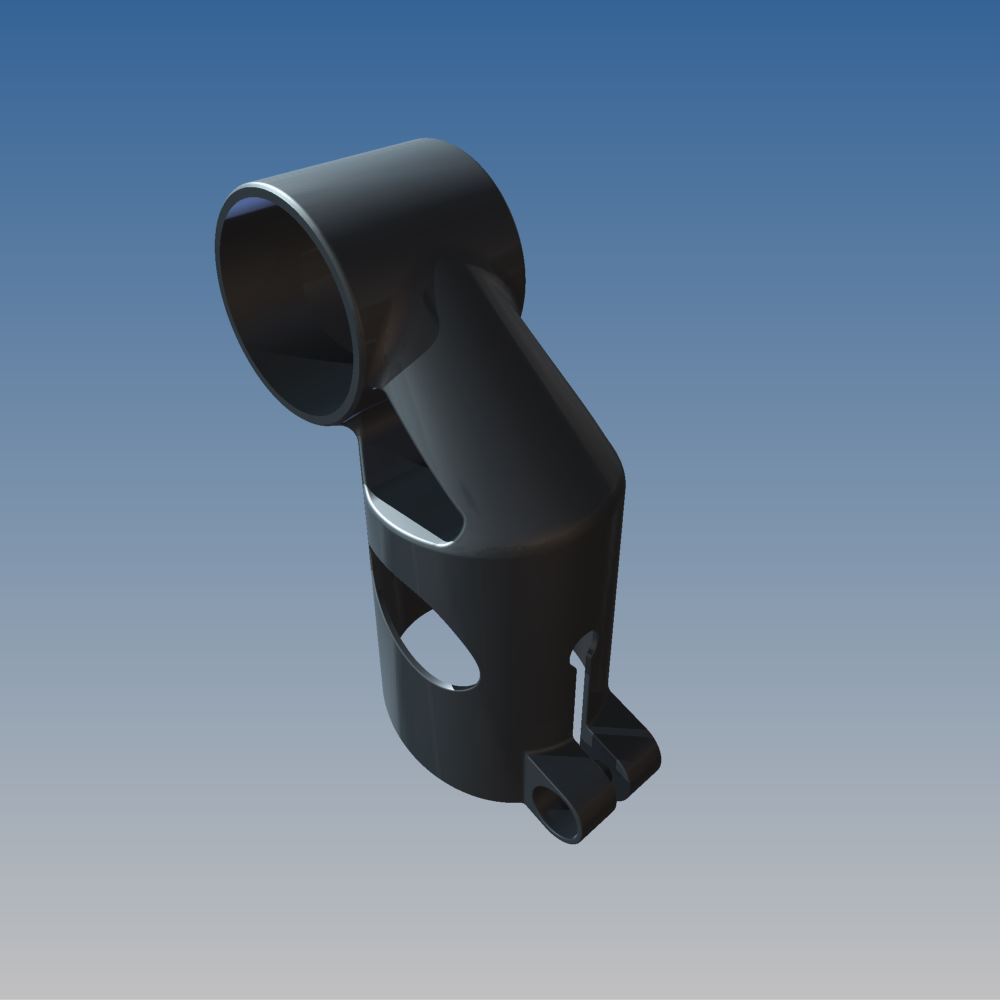
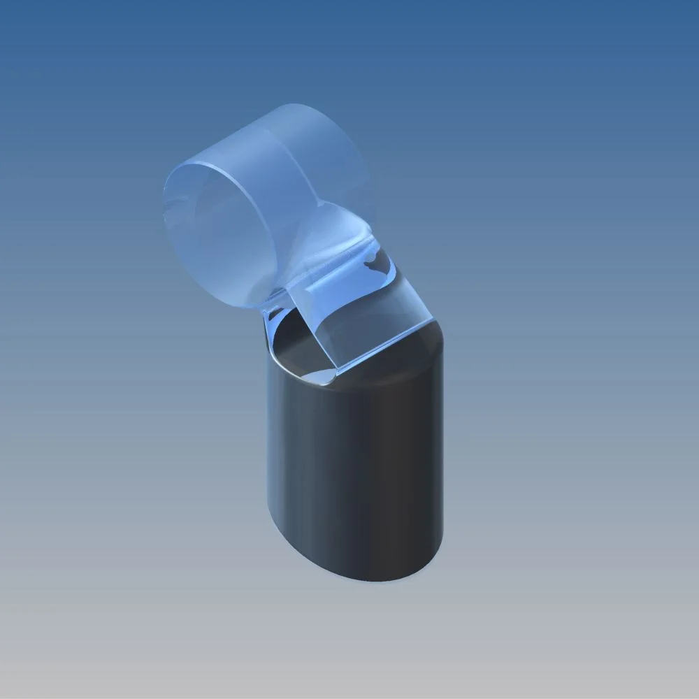