Manufacturing guy-at-large.

Filtering by Tag: modeling

Desk update

Added on by Spencer Wright.

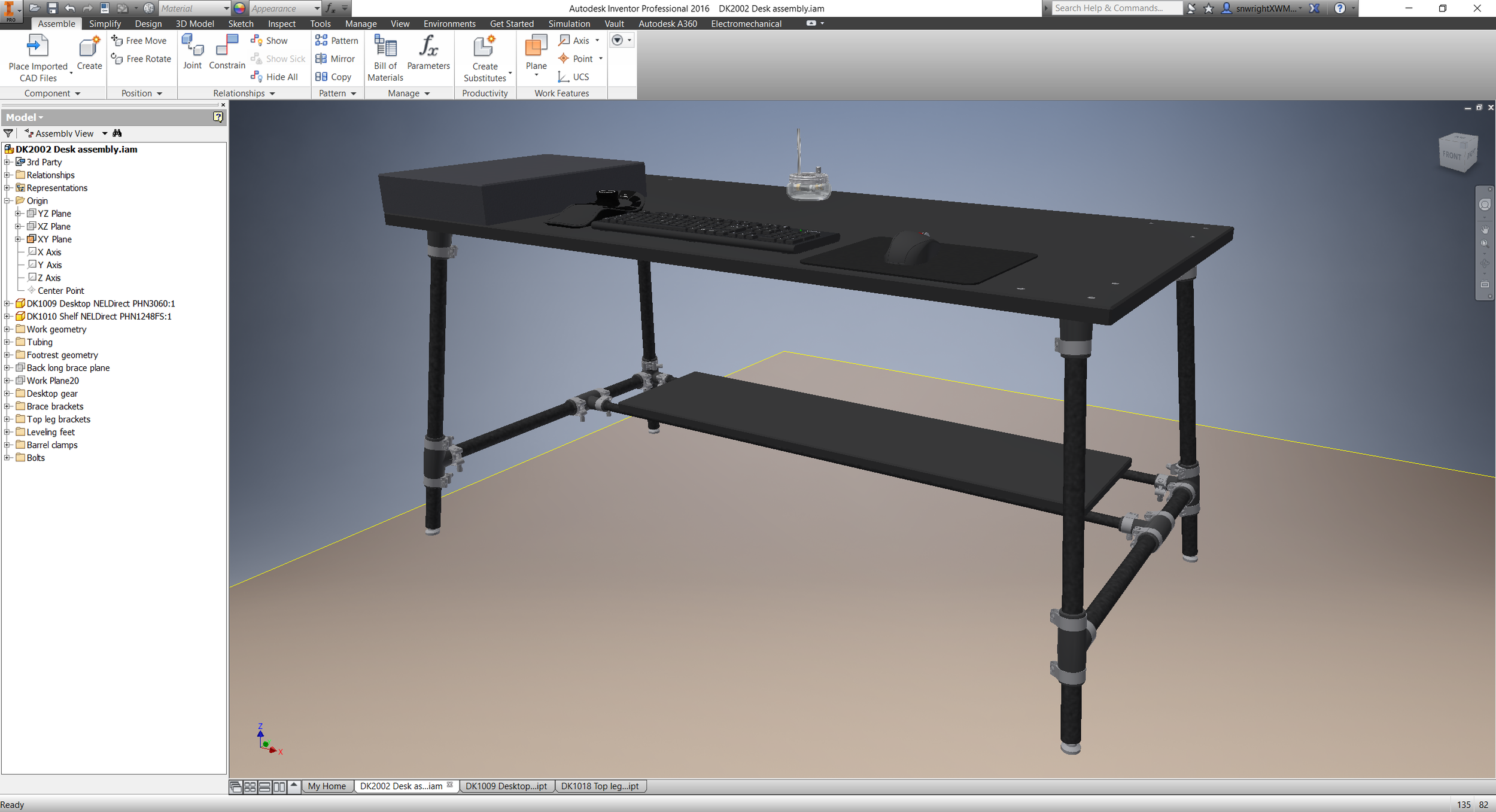
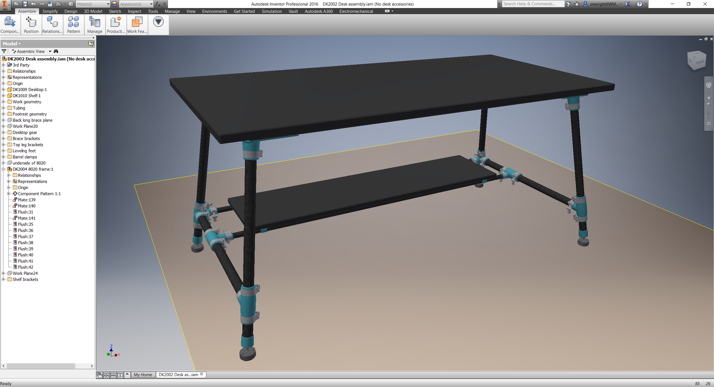
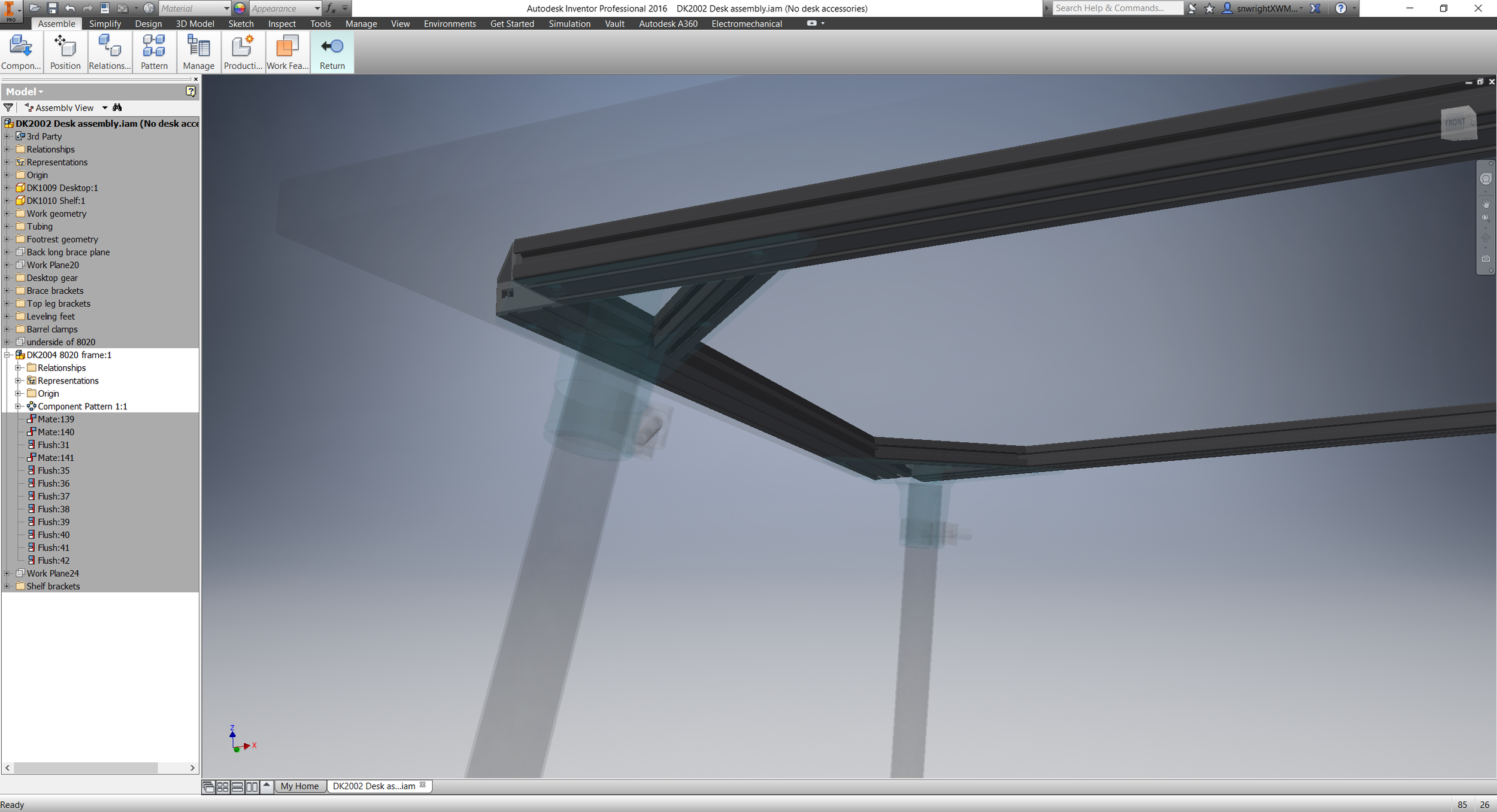
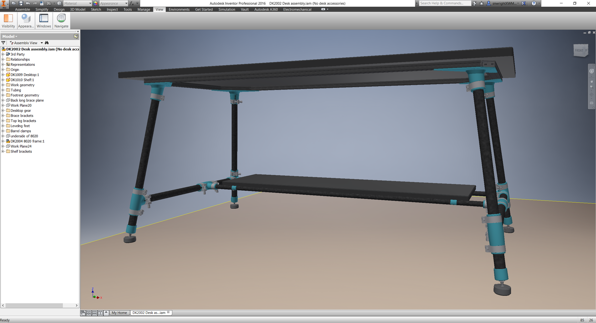
I was able to spend a little more time on my desk this past weekend, and got it nearly done:

A quick changelog:

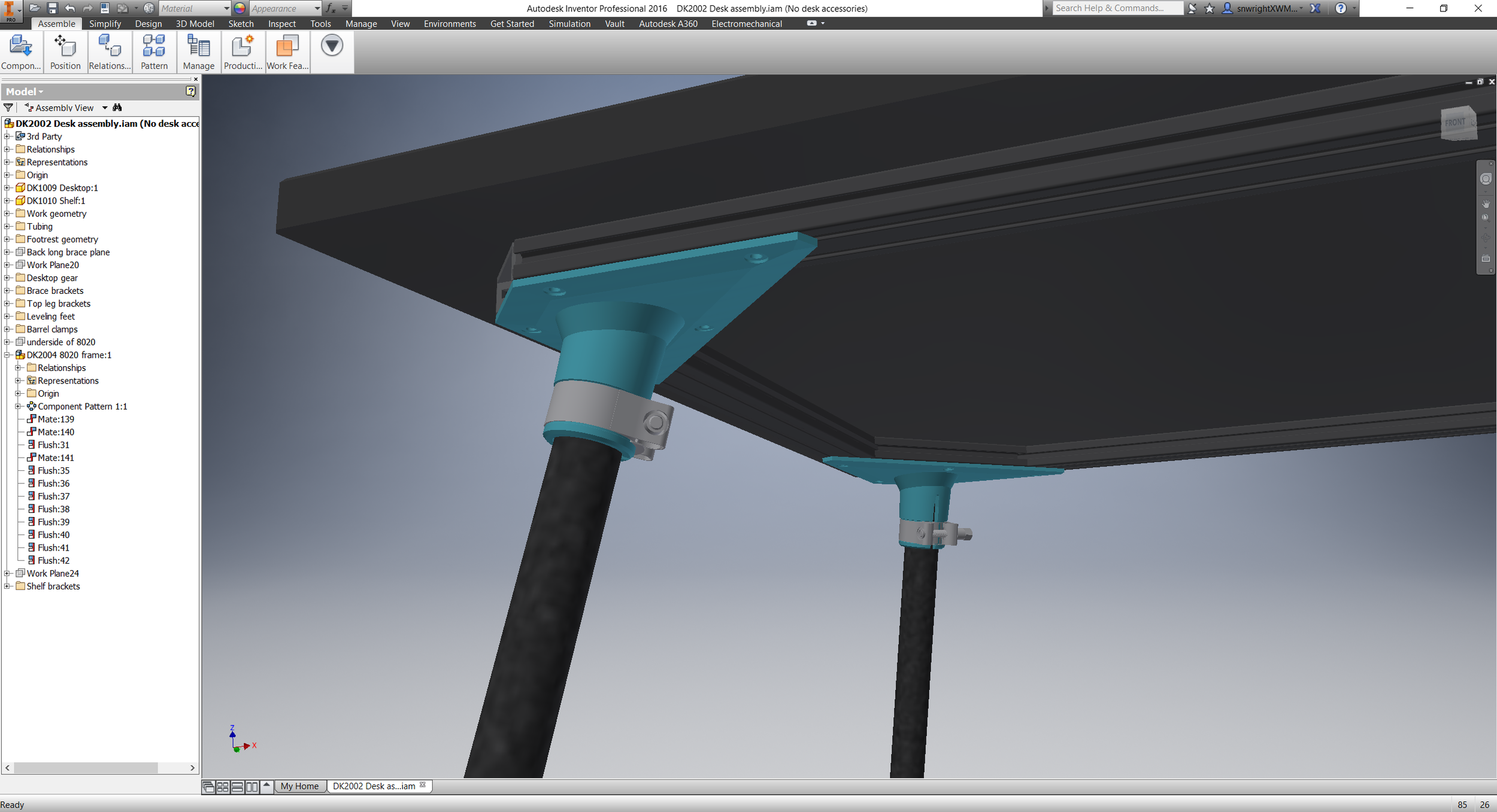
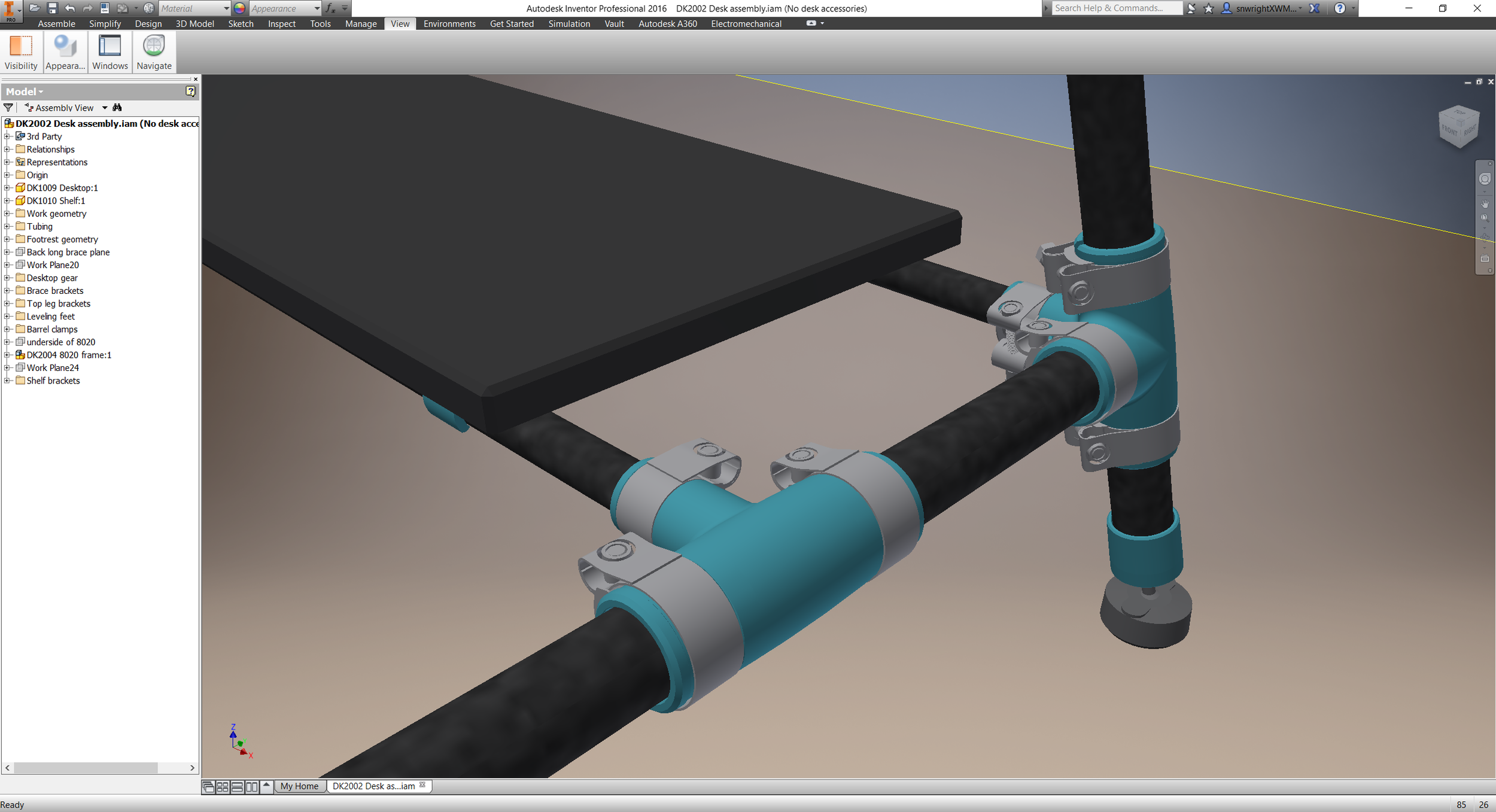
  • Added a frame to the desktop. I'm planning on using 1" phenolic resin (or *maybe* epoxy resin, if I can afford it) for the surface, and it needs to span almost 5'. At that length it seemed like a good idea to support the span, and I'm using an 8020 frame to do so. It's not the cheapest option, but means that attaching the surface will be easy. It also has the advantage of allowing me to attach other accessories (a power strip, my monitor stand, an architect's lamp or two) really securely as well.
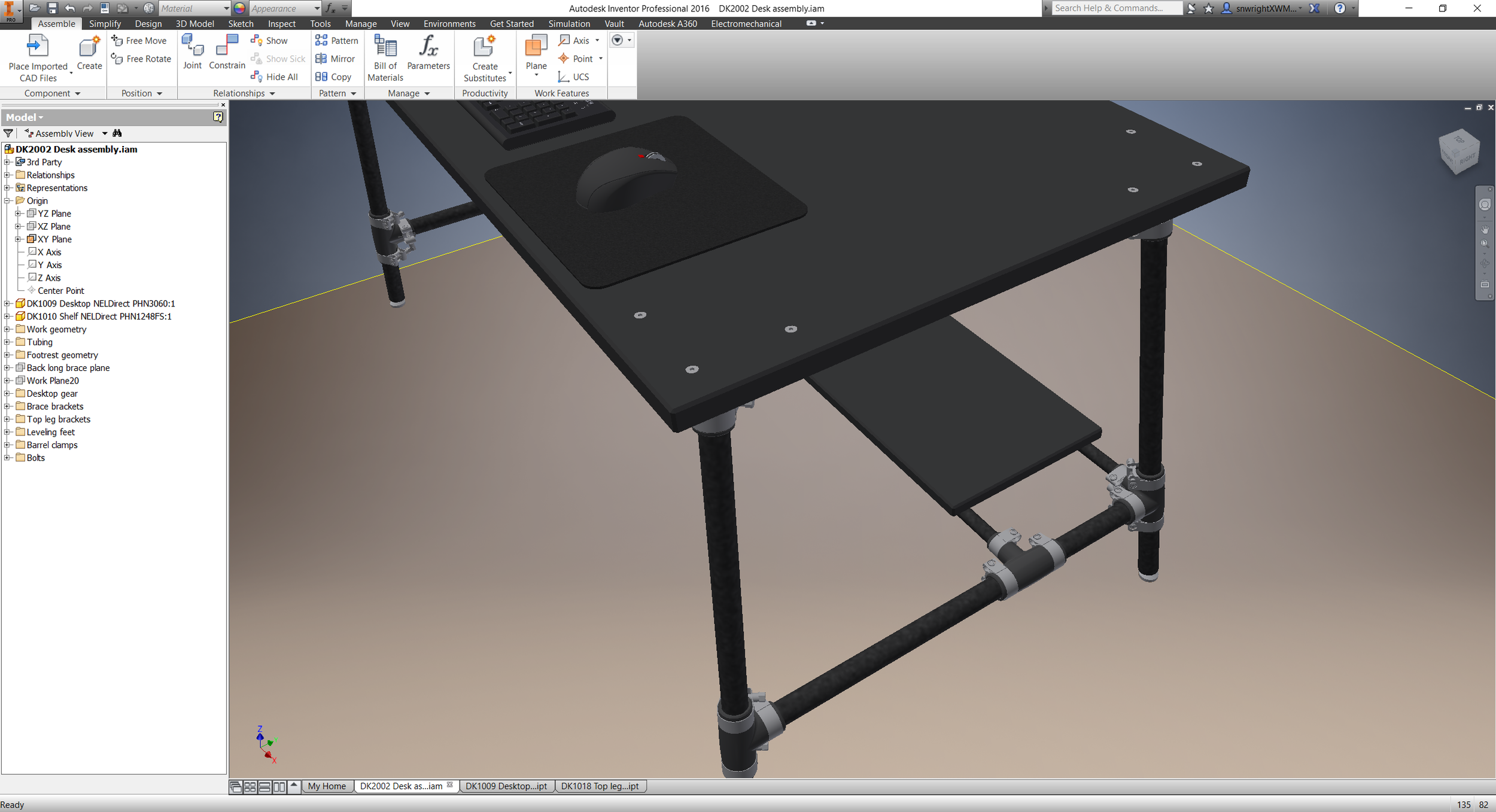
  • Added adjustable feet. These are nylon with a rubber pad, and they thread into nut inserts that'll be installed in the leg caps. 
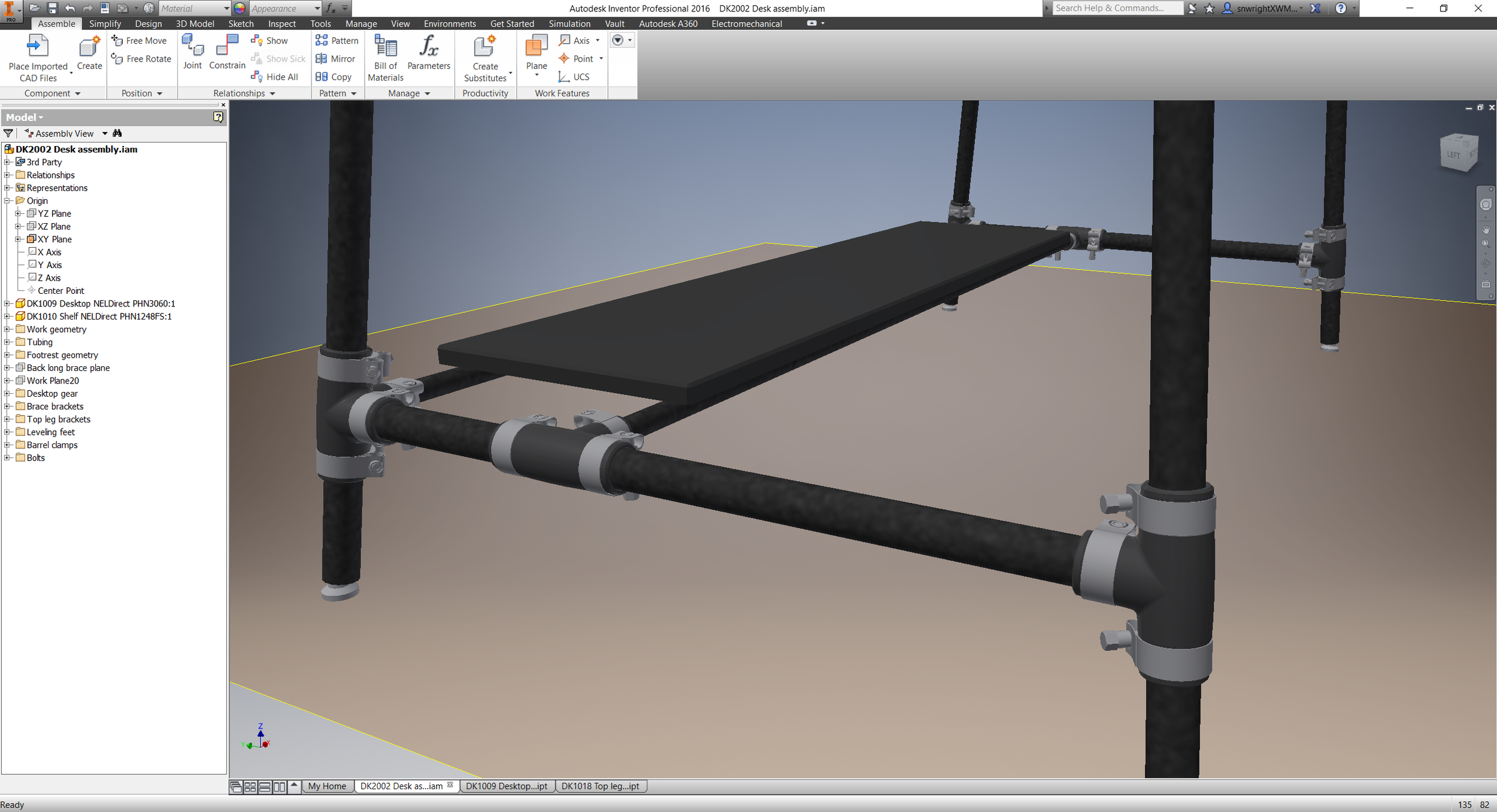
  • Added shelf clips to hold the lower shelf onto its supports. I think that the shelf will just rest there - the clips should snap more or less securely onto the supports, and I don't think I need to attach them any more firmly than that.
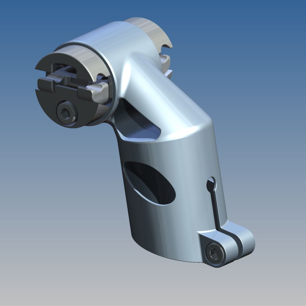
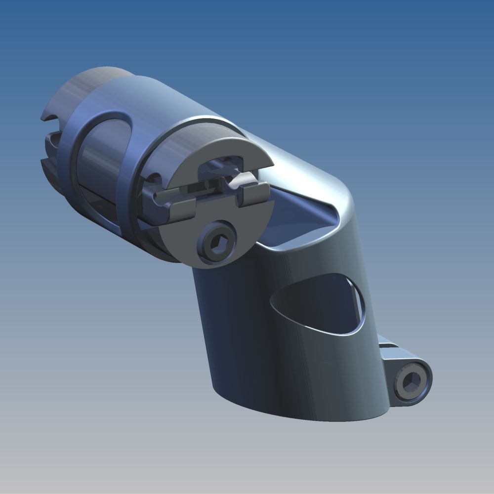
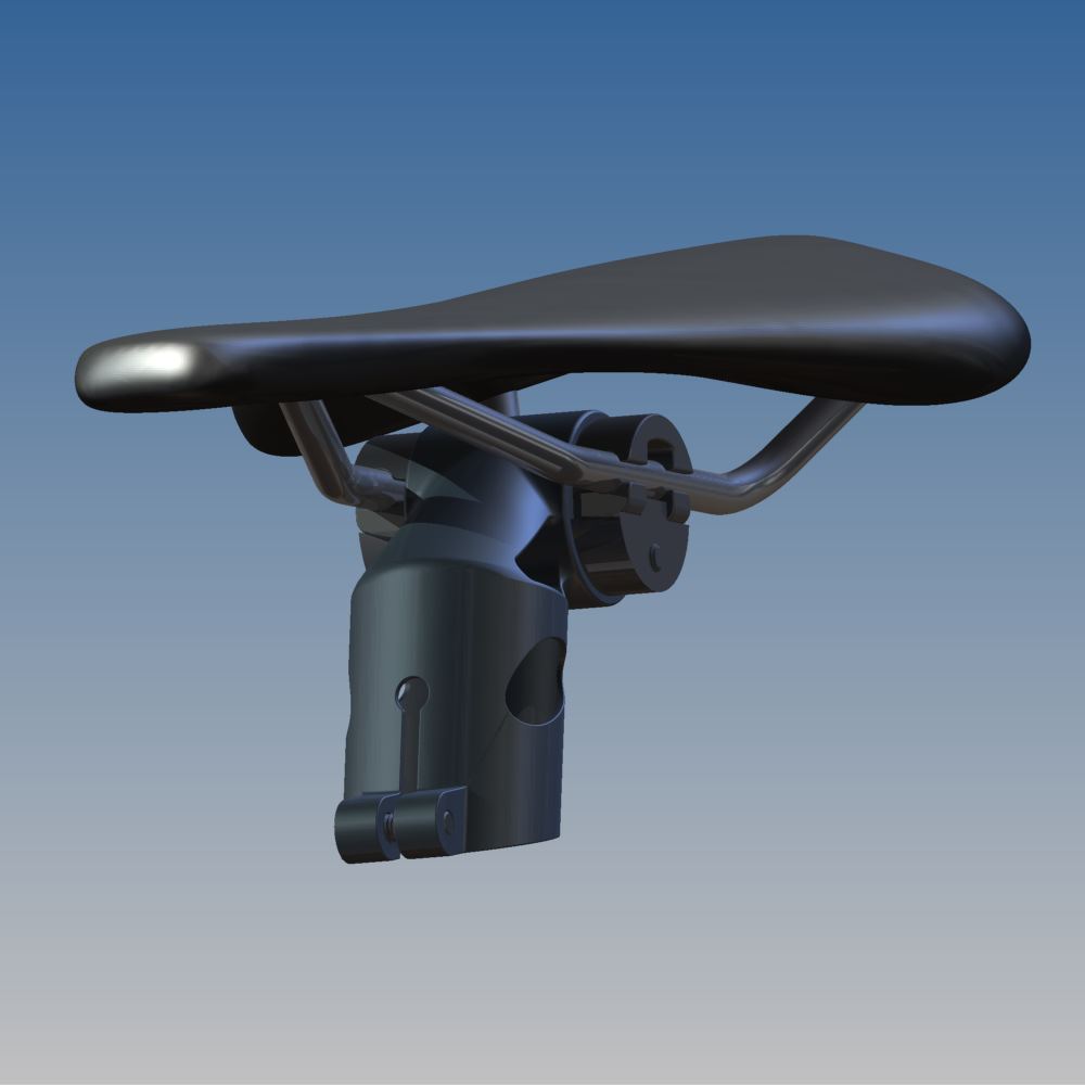
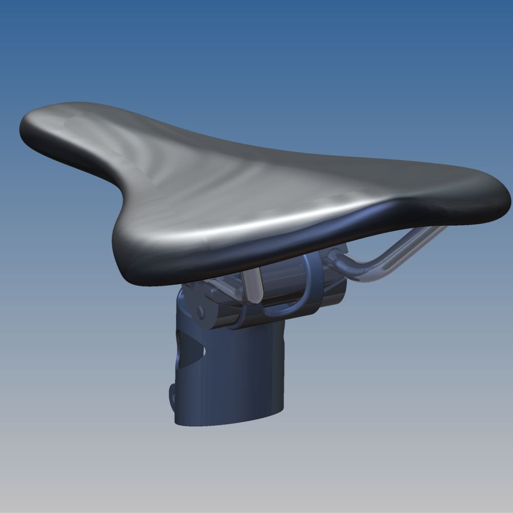
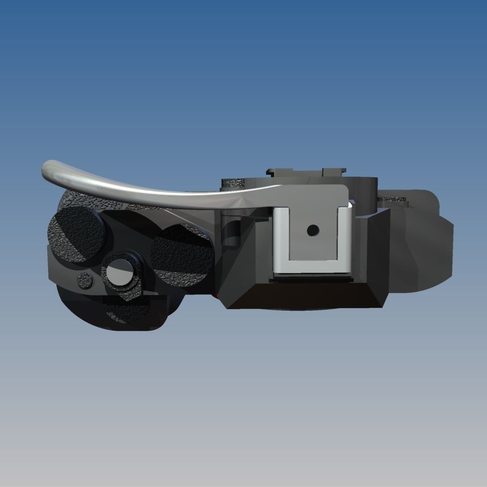
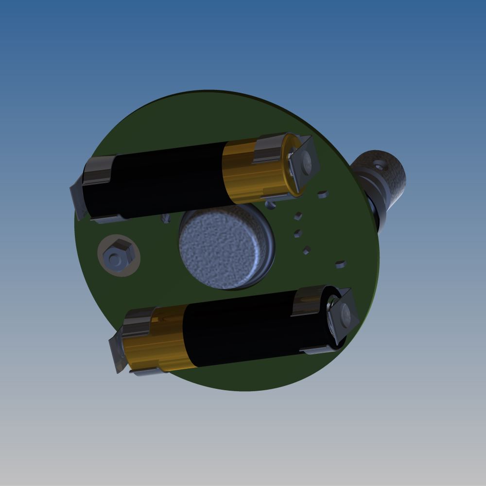
  • Other small changes to the leg brackets. I had an early prototype printed by Form Labs in their "Tough" resin, and was pretty impressed with the results; the part came out true to size and clamps onto my carbon fiber tubing really well. I'm having a few more parts printed now, and will rig up a bigger test assembly to confirm - but with the combination of my leg geometry and the Form Tough's high tensile strength and elongation at break, I'm confident that it'll work well.

Time allowing, I'll order the rest of the stock and cut-to-order parts in the next week or so. Pretty excited :)

Desk update

Added on by Spencer Wright.

Some changes to my desk design:

In no particular order:

  • I rebuilt about 90% of the model so that it's driven off of an Excel spreadsheet. It took a little while, but makes updating tubing diameters *so* much faster.
  • The tabletop and shelf are designed to be phenolic resin; the shelf doubles as a footrest. I'm a bit worried that the long span on the tabletop will result in bounce, but that'll be relatively easy to fix if it happens.
  • The frame tubes are filament wound carbon fiber throughout.
  • The lugs/brackets are all slotted; they'll be printed. The band clamps are a little bulky for my taste, but the practicality of making the frame modular is just too appealing to me. Plus, I'm pretty sure they'll distribute the clamp force evenly and be plenty strong to hold the frame together.
  • My current plan is to drill and countersink the tabletop and then use flat head screws with washers & nuts to fasten the leg brackets. 
  • The legs are angled, and I'm planning to use swivel mount feet with rubber pads on them. I'll install nuts in the bottom of the legs (method TBD) to hold the feet in place.
  • Having dummy models to serve as Utah teapots is *really* nice. I'm still missing my Wilton vise, Gerstner tool chest, and monitor/laptop stand, but none of those is worth the time it'll take to model them.

I'm pretty happy with this so far - hoping to have it together soon :)

(Another iteration of my) Bike stem

Added on by Spencer Wright.

This.

The lattices here were, obviously, designed in nTopology Element Free (which is free!). I happen to have done the mechanical design in Inventor, but the rendering was done in Fusion 360 (effectively free, and totally capable of doing the mechanical design as well). I separated face groups and remeshed surfaces in MeshMixer (free!), and very well could have done the booleans there too (I used netfabb).

^ I just think that's a bit remarkable.

Anyway, it's ready. Printed part (DMLS titanium) soon.

Some quick modeling

Added on by Spencer Wright.

It's been a little while since I've played with this design, and I enjoyed getting back in to it. To be honest I'd like to spend a few days working on the model (I'd probably tear it down completely and start from scratch) but for now this is looking pretty nice.

Incidentally, T-splines continue to be *really* weird - and super cool. I really wish I had a more powerful computer; I suspect that would improve the experience significantly.

Why not Github for mechanical design files

Added on by Spencer Wright.

I spoke today to Jon Placa @ ProtoExchange about how we're using Github on The Public Radio. In a followup email, he asked: "Is there any reason why you aren't using Github to host your actual design files (beyond gerbers)?" My reply:

No singular reason. But...
  • Only I work on our mechanical design, so there's no need to collaborate.
  • When I was collaborating on mechanical design (last job), I used Autodesk Vault - which is actually pretty good.
  • Mechanical design is even more fragmented - it's not as if me posting .ipt and .iam files on Github means they're really useful to anyone else, because maybe they're on Solidworks or an earlier version of Inventor - or, more likely still, on some consumer grade system.
That said, the original goal was to be open with all of it, and I would like to post those files there too - if only for posterity's sake.

Updated drawings

Added on by Spencer Wright.

Changes:

  • Oriented all drawings the same way
  • Much improved BOM with screw & nut specs & names, more details on custom parts
  • New spacer setup
  • Section & detail drawings show interface between spacer, lid, and antenna/potentiometer

Full PDF here, in case you're really curious.

An idea I'm not so sure about

Added on by Spencer Wright.

We need a better way to sandwich The Public Radio together. It needs to be a spacer between the speaker and the lid, and needs to insulate the antenna from the lid, and probably needs to interface with the potentiometer too.

This is my first real crack at it. Not sure how I feel about it. Will probably be expensive.

Needs more work + some supplier DFM feedback.

Speaker mods

Added on by Spencer Wright.

One of the big pain points to date on The Public Radio is that our speaker - a Dayton Audio CE32A-4 - was *not* designed to be PCB mounted. Like most good quality full range speakers (it's one of the most expensive items on our BOM), it's got solder lugs, which are designed to have wire soldered to them.

So, why did we choose this speaker? Partly because of sound quality - it's really the best available given our size constraints. It was also relatively easy to attach to on the cone side; the plastic flange is sized nicely and has four good screw holes in it. And anyway, we figured we could work something out if we ever had to build a whole lot of radios.

Fortunately, at 2000 units we start to be in the range where getting custom PCB pins could make sense. It'll cost us some time (13-15 weeks) but that's okay if we decide quickly - and we'd probably wait that long anyway just getting the full quantity from our supplier. So I drew up a basic version of the pins we'd want and sent it to Dayton:

I'm not sure what the net cost will be on the parts, but the assembly will be significantly less expensive and *much* more reliable. 

Banners

Added on by Spencer Wright.

In a rush, I made these last night. One is a proper banner ad:

And the other is more boxy, for a display ad:

I'm kind of shocked that I modeled that jar, but it has ended up being *so* handy. These were not totally seamless to make (I went from Inventor .iam -> Inventor .ipn -> Inventor .idw -> export as .dwg -> AutoCAD -> export as .pdf -> Illustrator), but they could have been much worse.

The taglines & formatting were tough, and I'm still not totally convinced they're perfect... but for a few hours of after-work hacking, I think they came out pretty well.

Bed -> AutoCAD

Added on by Spencer Wright.

My bed project is coming along. The Inventor model is done (minus possibly some marginal edits) and I'm now processing it for production.

The way this will work: I buy ~20 sheets of cabinet grade plywood (probably black walnut, from Robert's Plywood) and have it shipped to Old World Moulding. They'll take my part list and cut the pieces up in a big overhead router. The parts will then be finished with a light, clear polyurethane.

In order to make sure that all the pieces have the intended grain orientation, Paul @ Old World asked me to lay them all out in AutoCAD. Which totally makes sense.

Except that I've basically never used AutoCAD. I played with it a bit as a kid (incidentally, it was also on a bed project), but I've only used it in passing as an adult. 

Anyway, I broke it out today and I think the results are passable. It took me a while to get the basics (units, etc) down, but I drew a bunch of 4'x8' rectangles to show the plywood sheet sizes, and then exported each part's face as a DXF and copy/pasted it onto a piece of plywood.

The result: Nineteen sheets should cover us for three full beds. I'm a little disappointed with some of the grain orientations, but it'll be fine. I'm also a bit worried about the nested parts (on the six nearly identical sheets on the left); we'll see what Paul says about that.

The only other thing of note is the red boxes on the right. Those parts have a beveled cut on one side, which needs to be done on a table saw (the router is only 2-axis), so I'm adding a bit of material to the parts.

I'm *hoping* that this shit gets cut this week. It'll be really nice to have a project wrap up :)

More Bed

Added on by Spencer Wright.

This is mostly done.

The base has a six interconnected cubbies in it. Lift the mattress to access their doors. The doors themselves are perforated for ventilation (I figure that's a feature, right?) and to make it easy to see what's inside (pretty sure this'll be useful). 

The headboard has a bunch of little slots on the sides for storage. The one thing I really want to add still is a convenient way to charge your phone there, plus an outlet for a light (I'm thinking a pair of small clip-on fixtures similar to a Luxo). I might just hardwire in an outlet (with integrated USB) on each side of the headboard and run a piece of fixture cord out of the back... we'll see. I figure there's a pretty good chance that you've got an outlet somewhere behind the headboard, so routing the power conveniently out to each side is kind of a nice courtesy. 

The big thing that's missing here is a fastener system for the headboard. The base basically just snaps together, but the headboard will need a few fasteners. I'm trying to use barrel nuts (a.k.a. "cross dowel nuts") but it'll require a bit of finagling to make it work.

The one thing I'm a bit insecure about is the top of the headboard. I couldn't find a good way to terminate the slanted part, so I just let it stick up a little. That top shelf isn't going to be very useful for storing stuff, but I guess at least nothing will fall off the front.

Oh, and the headboard is a little overbuilt... but it's okay for now.

Topper progress

Added on by Spencer Wright.

This is still happening.

It's been slow, but my metal powder bed fusion (aka DMLS, LaserCUSING, selective laser sintering, etc.) seatmast topper is moving forward. With any luck, I'll have a part in production in a week's time.

I've made some small changes to the design. The biggest thing is the hole in the back of the part, which is meant to reduce mass. I also modeled the threads in the clamp, which will help my manufacturer print the threads.


Choosing a job shop for this has been interesting. Since my post on DMLS pricing, I've had a bit of interest on my project. My hope has been that I'd be seen as more of a partner than a customer,  but the extent of that remains to be seen. Selling a partnership is something I'm green at, and companies that deal mostly with corporate and institutional buyers don't necessarily think of investing time into a project that has an indirect upside.

Nonetheless, I think there's something to it. This project is partly product, partly experiment in advanced logistics. The information I'm learning on the subject is free for anyone to see, but the partners that I'll end up working with will develop unique experience working on a thin-wall, consumer facing part. There aren't a ton of people working on that kind of thing, but I expect that'll change in the near future. My hope would be that my partners would agree with me, and would see this project as an opportunity to develop additional capabilities at a relatively low expense. 

Nevertheless, I'm determined. And I'm looking forward to having a piece of laser sintered titanium in my hands, too :)

Working on The Public Radio v1.3

Added on by Spencer Wright.

Screenshots from both Zach and myself - we've swapped back and forth on layout duties.

The FM IC (Si4831) is at the top of the board; to its left is the tuning circuit and trimpot. On the right edge of the board is the power & volume pot, and on the bottom is the amplifier, and on the left is the antenna connector. The middle of the board has a big cutout for the speaker body to fit through; we'll solder the speaker terminals directly to the board.

I got a little cute with the restricts near the antenna trace, and ditto on the power trace along the left edge of the board :)

Meanwhile, I spent a little time today modeling the battery connectors in Inventor:

Finding nice through-hole AA battery connectors is *tough.* I'm hopeful about these - I think they'll hold the cell firmly but allow for easy removal too. The only downside is that they're not polar in any way, so we'll need to mark the PCB clearly to show which direction the batteries need to face.

Our antenna standoff is kind of exciting too. We're running a trace to a plated hole (with a *big* pad) on the PCB, and then fastening a male-female threaded standoff to the hole with a hex nut. The antenna itself will thread into the standoff, making it easy to remove/install for shipping, transportation, etc.

We're in the process now of getting quotes for a couple of custom pieces of hardware: the antenna, the knob, the potentiometer, and the speaker gasket. We've also gotten a few quotes for the lid, which will either be stamped or laser cut stainless steel. And when PCBcart comes back from Chinese New Year, we'll order a batch of new boards to get into the hands of our beta testers.

This is an exciting time in the project. Things are coming together quickly :)

Public Radio Progress

Added on by Spencer Wright.

The last few days have been a bit of a whirlwind. 

First, we visited Todd to discuss some circuit layout concerns. On the way over we nabbed a cheap radio at RadioShack, and took it apart with Todd.. 

narrat1ve-1.jpg

What we found was really interesting. The device uses a different chip than we had been prototyping with, and as a result their circuit is *much* simpler. Our chip (Silicon Labs' Si4703) requires digital tuning, which we were accomplishing with a microcontroller. But RadioShack was using the Si4822, which is mechanically tuned. The result is drastic from a circuit standpoint - they no longer need a voltage regulator, or a microcontroller, or a bunch of additional passive components on the board. They're also in a better position re: noise on the board: an MCU (and a voltage regulator too) will produce a bunch of noise that might get on the antenna, affecting reception. RadioShack doesn't need to worry about this at all.

Over the past few weeks, we've been looking for just a breakthrough like this - a way of rethinking the problems we were dealing with. Our issue was that we were stuck conceiving this as an Arduino-descended product, which it doesn't need to be. 

public radio hammer nail-1.jpg

We also made a bit of progress reengineering the hardware layout of the board. Our new design (this is just the board layout, not the circuit schematic) will be significantly easier to assemble, program & service.

public radio hammer nail-2.jpg

We're also pretty sure we can shorten the antenna *significantly.* The mockup here shows a custom solid stainless steel antenna, 50mm long. I rather like it, and it's designed such that a longer telescopic antenna can be swapped in easily. 

short antenna round pcb full assy.jpg

Our PCB will now be circular, and we're soldering the potentiometer and speaker directly to the board. There will be a bunch of SMT stuff on the top (same side as the speaker & pot) and a battery back and trimpot (not shown) on the bottom.

I *really* like where this is headed. More updates soon.